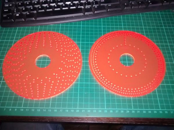
How to get 89 divisions from a dividing head
How to get 89 divisions from a dividing head
- This topic has 48 replies, 12 voices, and was last updated 20 March 2015 at 21:54 by
 Anonymous.


- Please log in to reply to this topic. Registering is free and easy using the links on the menu at the top of this page.
Latest Replies
-
- Topic
- Voices
- Last Post
-
-
1911 Harley Davidson 7D twin
Started by:
Luker
in: Help and Assistance! (Offered or Wanted)
- 3
-
28 February 2025 at 11:01
keith hodgson
-
Workshop wiring
Started by:
robin coleman
in: Beginners questions
- 16
-
28 February 2025 at 10:36
SillyOldDuffer
-
Centec 2B Mill Table—Surface Grind or Scrape?
Started by:
Graham Horne 2
in: Manual machine tools
- 5
-
28 February 2025 at 10:36
Graham Horne 2
-
Gear Cutting Problem
Started by:
Alan Charleston
in: General Questions
- 12
-
28 February 2025 at 10:09
JasonB
-
Scam – Close but no Cigar!
Started by:
Chris Crew
in: The Tea Room
- 9
-
28 February 2025 at 10:05
Michael Gilligan
-
No logging in to classifieds
Started by:
Bob Worsley
in: New Forum Software questions, comments and Test Threads
- 2
-
28 February 2025 at 09:54
Michael Gilligan
-
Metal strands in graphite packing
Started by:
Tony Rowe 1
in: Beginners questions
- 6
-
28 February 2025 at 09:52
noel shelley
-
Slow Again?
Started by:
JasonB
in: Website Questions, Comments, and Suggestions
- 14
-
28 February 2025 at 08:21
SillyOldDuffer
-
Points, Turnouts for French readers
Started by:
Speedy Builder5
in: Locomotives
- 1
-
28 February 2025 at 08:12
Speedy Builder5
-
Discussion on the Future Direction of Model Engineer and Workshop
1
2
…
11
12
Started by:
Neil Wyatt
in: Model Engineer.
- 70
-
27 February 2025 at 23:35
duncan webster 1
-
Vickers Inverted Engine
1
2
Started by:
JasonB
in: Stationary engines
- 10
-
27 February 2025 at 22:27
Nigel Graham 2
-
Strange German Lighter
Started by:
Vic
in: The Tea Room
- 8
-
27 February 2025 at 21:38
Nigel Graham 2
-
Ford Transit
Started by:
Vic
in: The Tea Room
- 2
-
27 February 2025 at 21:33
Nigel Graham 2
-
What steel
Started by:
Peter Simpson 3
in: Beginners questions
- 6
-
27 February 2025 at 20:58
JasonB
-
Source for trangular carbide inserts.
Started by:
Andrew Tinsley
in: General Questions
- 9
-
27 February 2025 at 20:40
JasonB
-
Best way to wire up 4 motors to a 4QD controller
Started by:
Michael Callaghan
in: Locomotives
- 6
-
27 February 2025 at 18:23
Robert Atkinson 2
-
Vehicle Tax
Started by:
Michael Gilligan
in: The Tea Room
- 14
-
27 February 2025 at 16:34
Oldiron
-
WM14 mill/drill gears
Started by:
michael howarth 1
in: General Questions
- 2
-
27 February 2025 at 09:06
michael howarth 1
-
Pivot hole bushing
Started by:
Plasma
in: Clocks and Scientific Instruments
- 6
-
27 February 2025 at 06:56
Plasma
-
Magnetic optical punch
1
2
Started by:
Fulmen
in: Workshop Tools and Tooling
- 10
-
26 February 2025 at 20:33
Fulmen
-
Homemade Headstock Lathe 1 fondry work
Started by:
celso ari schlichting
in: General Questions
- 4
-
26 February 2025 at 20:32
celso ari schlichting
-
How Would I Machine this CAD designed Ratchet
1
2
3
Started by:
SillyOldDuffer
in: CAD – Technical drawing & design
- 16
-
26 February 2025 at 18:41
JasonB
-
Drilling on VMC Mill
Started by:
Vic
in: Manual machine tools
- 4
-
26 February 2025 at 18:21
Dave S
-
DRO Origin Setting
1
2
Started by:
Peter Cook 6
in: Beginners questions
- 21
-
26 February 2025 at 18:14
bernard towers
-
Electric magnet
Started by:
robin coleman
in: Electronics in the Workshop
- 5
-
26 February 2025 at 17:30
robin coleman
-
1911 Harley Davidson 7D twin
Latest Issue
Newsletter Sign-up
Latest Replies
- 1911 Harley Davidson 7D twin
- Workshop wiring
- Centec 2B Mill Table—Surface Grind or Scrape?
- Gear Cutting Problem
- Scam – Close but no Cigar!
- No logging in to classifieds
- Metal strands in graphite packing
- Slow Again?
- Points, Turnouts for French readers
- Discussion on the Future Direction of Model Engineer and Workshop

