How to cut a tri-lobe bore in a change gear (Schaublin style bore)

Advert

How to cut a tri-lobe bore in a change gear (Schaublin style bore)

Home Forums Workshop Techniques How to cut a tri-lobe bore in a change gear (Schaublin style bore)

Viewing 22 posts - 1 through 22 (of 22 total)
  • Author
    Posts
  • #480090
    Adam Harris
    Participant
      @adamharris13683

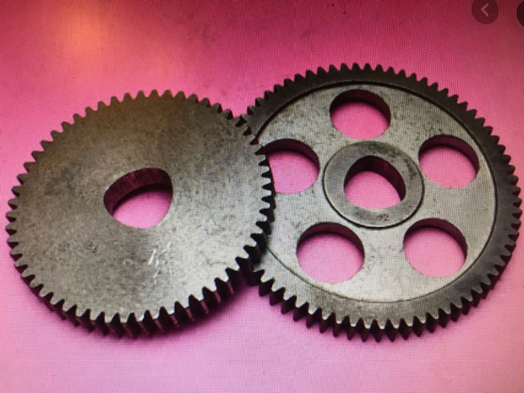
      I am wondering how one would go about cutting a tri-lobe bore in change gears (Schaublin type), using a non-CNC mill with DRO. Any theories on this, or even practical experience? I attach a photo of what i am talking about.

      Edited By Adam Harris on 15/06/2020 23:37:08

      Advert
      #16172
      Adam Harris
      Participant
        @adamharris13683
        #480092
        Adam Harris
        Participant
          @adamharris13683

          tri-lobe bore

          #480094
          Jeff Dayman
          Participant
            @jeffdayman43397

            If you have access to a rotary table, you could drill the three corner holes first, then mount the gears off centre on the rotary table and remove the waste with three arc cuts. If you made a sub-table for the rot tab with two pins close fitted to two corner hole centres the gears could be positioned and clamped located at the pins, pins removed, cuts made. Careful measurement and planning before any cuts would be the order of the day I think.

            #480095
            Martin Connelly
            Participant
              @martinconnelly55370

              The OEM gears were probably broached, the cost of the broach would be spread over a lot of gears and would save a lot of messing around with other methods.

              Martin C

              #480096
              Clive Foster
              Participant
                @clivefoster55965

                Adam

                You need to cut three circular arcs with the end / intersection points defined by the centre of the milling cutter being at the vertexes of an equilateral triangle.

                Theoretically its just a matter of sorting out the right size milling cutter and the necessary offset of the gear relative to the rotary table centre and cutting three arcs.

                In practice jigging isn't going to be simple for the second and third sides as you are cutting away at the gear centre bore and cannot use it for a reference. Most obvious way is to drill three suitable holes in the gear blanks to fit three pins in equilateral triangle formation on the jig.

                Jeffs suggestion of creating the three corner holes first and using internal pins may not work as you will be cutting into the pins at the ends of the arcs. $64,000 question is how much of the locating pin gets cut away. If you have more than half the pin left it should be sturdy enough for location.  Or maybe pull the pins after clamping the gear in place. If done carefully things ought to stay put.

                Sorting out the appropriate size of milling cutter looks to be a serious exercise in CAD geometry. Easy enough to design in the first place but much harder to reverse engineer. I suspect the originals were broached so no guarantee that the tips of the figure can be cut with a standard size end mill. Errors due to using the wrong size end mill will appear on the tips so it ought to be possible to arrange an acceptable tolerance.

                Fundamentally its the same challenge as machining the housing for a Wankel engine. I believe folk have successfully modeled such so perhaps there are build threads or frum chats covering the process.

                Clive

                Edited By Clive Foster on 16/06/2020 00:12:49

                #480099
                Adam Harris
                Participant
                  @adamharris13683

                  Thanks Clive. Would it be very easy (ie cheap!) for a proper CNC machine shop to simply map out the exact shape with a feeler probe run around an existing bore , memorize it and cut out the bore of any change gear handed to them in exact replication? I don't know if that is how CNC machines can work.

                  #480107
                  Hopper
                  Participant
                    @hopper

                    Easy enough to do with a rotary table as said. Might need a sub table making from a bit of flat plate to accommodate the large flank radius. First step would be to measure the two radiuses ie the points and flank radiuses. Drill bits could be used to measure the points and various round objects for the flanks. Or turn a disc to an exact match and measure the disc.

                    A cnc shop could scan the original and duplicate it. Youd be lucky to find one whod give you much change from 100 beer tokens though. Most are not interested in small one off hobby jobs.

                    Edited By Hopper on 16/06/2020 02:24:00

                    #480110
                    Jeff Dayman
                    Participant
                      @jeffdayman43397

                      Clive Foster – The locating pins would NOT be cut away – suggest you read my post again – clearly says "clamped located at the pins, PINS REMOVED, cuts made". I did mention making and using a sub-table.

                      As I also said "careful measurement and planning before any cuts are made" is important. Until that is done, and the OP knows what geometry he is dealing with, it is difficult to plan tooling and cuts.

                      This geometry is NOT the same as the generated epitrochoid shape in a Wankel engine housing, not sure why that was mentioned.

                      #480111
                      pgk pgk
                      Participant
                        @pgkpgk17461

                        1) Surely there's a low tech/time intensive solution here? How about chain drilling by co-ordinates and filing it out? Trace the centre onto graph paper perhaps. It might require some pratting about to scale the graph paper to it but the odds favour this fitting a metric scale.

                        2) My simple brain and low level of CAD practice would probably start by tracing out the centre, importing the pic into a CAD layer and pratting about with circle sizes for a fit to the apices. One can start with an array of dill bits for a visual fit to the original. If a standard endmill won't fit then a boring head +/- DIY boring tool will sort those.

                        Sorting out the centre of the arcs can also be done empirically. If they end up within the body of the gear then 3 drill holes into the gear (they look way outside the centre hole) or in a base-board outside the gear. Additional limit pins can be placed in a base-board as stops while the gear is rotated around each arc-centre pin in turn if one wants to mill the long arcs without a rotary table – if necessary bolting a handle or two to the gear for control and a band around the teeth?

                        pgk

                        #480113
                        Neil Lickfold
                        Participant
                          @neillickfold44316

                          There was a youtube video on drilling square and lobbed holes. It had a template that the tool followed and that inturn generated the shape hole.

                          #480114
                          DC31k
                          Participant
                            @dc31k

                            The Schaublin gear centre is not a proprietary item. It is made to a DIN standard (DIN 32711).

                            Put 'P3 polygon shaft' into Google and enjoy…

                            See: https://autodesk.i.lithium.com/t5/image/serverpage/image-id/481760iD30BCACD1A778304/image-size/large?v=1.0&px=999

                            For example, https://www.powertransmissions.co.uk/project/p3g-p4c-polygon-profiles-splined-profile-muff-couplings/

                            There is nothing complicated about it that requires CNC mapping. It is just three pairs of arcs.

                            Easily done on a rotary table with a fixture, some travel stops and a cutter of any diameter less than that of the smaller arc.

                            Edited By DC31k on 16/06/2020 06:44:59

                            #480115
                            John Haine
                            Participant
                              @johnhaine32865

                              Schaublin were obviously keen to stop people using generic change wheels! I'd be tempted to convert to use round holes like the rest of the world.

                              #480119
                              DC31k
                              Participant
                                @dc31k
                                Posted by John Haine on 16/06/2020 06:44:44:

                                Schaublin were obviously keen to stop people using generic change wheels! I'd be tempted to convert to use round holes like the rest of the world.

                                I think you rather misunderstand the Swiss psyche. If you read up on the polygon profile, from an enginerding point of view, it is the best thing since sliced bread.

                                What would you rather cut, something formed of a series of arcs that scales in a simple manner using a simple endmill and some knowledge of geometry or a horrible stub involute spline of 19 teeth that requires a complicated, dedicated and expensive cutter and a dividing head?

                                #480123
                                Michael Gilligan
                                Participant
                                  @michaelgilligan61133
                                  Posted by DC31k on 16/06/2020 06:50:01:


                                  .

                                  yes

                                  ”The three-circle construction may be performed with a compass alone, not even needing a straightedge.”

                                  https://en.wikipedia.org/wiki/Reuleaux_triangle

                                  … and the finite [rounded] intersections are the natural result of “using a thick pencil”

                                  MichaelG.

                                  Edited By Michael Gilligan on 16/06/2020 07:25:00

                                  #480128
                                  JasonB
                                  Moderator
                                    @jasonb
                                    Posted by Clive Foster on 16/06/2020 00:06:20:


                                    Sorting out the appropriate size of milling cutter looks to be a serious exercise in CAD geometry. Easy enough to design in the first place but much harder to reverse engineer. I suspect the originals were broached so no guarantee that the tips of the figure can be cut with a standard size end mill. Errors due to using the wrong size end mill will appear on the tips so it ought to be possible to arrange an acceptable tolerance.

                                    If using CNC you could and would use any cutter less than the diameter of the corners it would simply work out a path to follow them as arcs just like the three larger radius ones. In fact far more preferable to use a cutter smaller than any internal radii as it saves increasing cutter engagement which can lead to chatter.

                                    I suppose they could have used a pantograph as another option to cut the holes


                                    Edited By JasonB on 16/06/2020 07:42:25

                                    #480130
                                    John Hinkley
                                    Participant
                                      @johnhinkley26699

                                      I'm lucky enough to have a small engraving machine and I might try putting a milling cutter in the spindle and use one of the original gears as a pattern.  Set the pantograph ratio to 1:1 and off you. It might take a while, depending on the material, but would save a lot of faffing around with CAD and rotary tables. 'Course, you'd need to have access to an engraver, otherwise dig out that rotab!

                                      John

                                      edited for spelling and appalling grammar!


                                      Edited By John Hinkley on 16/06/2020 07:50:44

                                      #480131
                                      pgk pgk
                                      Participant
                                        @pgkpgk17461

                                        My tractor's PTO shaft has two similar shaped cross-section tubes, one sliding in the other to allow an extendable drive.

                                        pgk

                                        #480133
                                        JasonB
                                        Moderator
                                          @jasonb

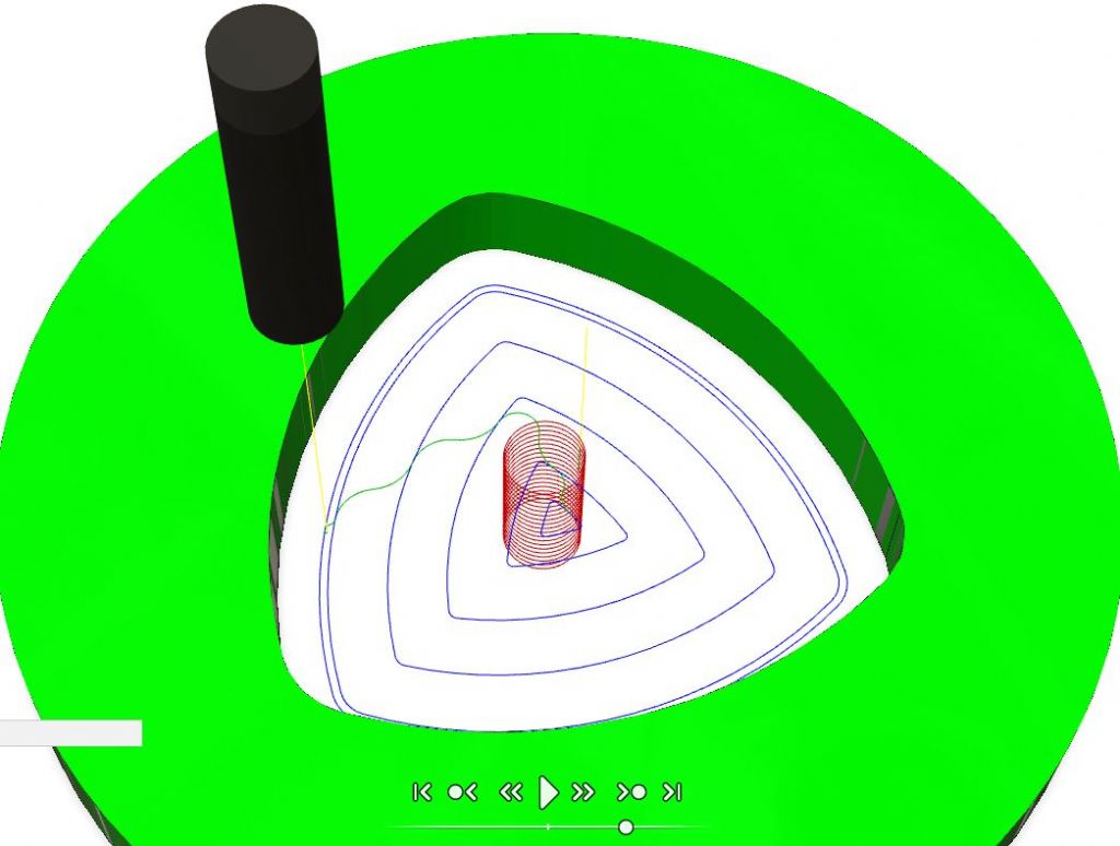
                                          For Clive, Blue lines show the path that the axis of the cutter follows, you can see that it is rounded as the tool follows the smaller corner radii by the offset which is half cutter dia, red is where it follows a helical path to bore down through the work before working it's way outwards in roughing cuts then a smaller stepover for a finish pass.


                                          trilobe path.jpg

                                          Edited By JasonB on 16/06/2020 08:12:38

                                          #480138
                                          DC31k
                                          Participant
                                            @dc31k

                                            Sorry to post again.

                                            The image at:

                                            https://autodesk.i.lithium.com/t5/image/serverpage/image-id/481760iD30BCACD1A778304/image-size/large?v=1.0&px=999

                                            is a screen capture of the technical catalogue of http://www.polygona.ch which used to be available as a pdf download. I can no longer find it there, and cannot work out how to find it on my old computer, but it is at:

                                            This contains comprehensive info. on the profiles and their geometry and is probably the best you will get without buying the DIN itself. Since it is a manufacturer's catalogue, I do not think there are restrictions on distribution.

                                            If someone with access to Scribd would download it and put it in a more accessible location, I would be very grateful.

                                            #480141
                                            John Haine
                                            Participant
                                              @johnhaine32865
                                              Posted by DC31k on 16/06/2020 06:50:01:

                                              Posted by John Haine on 16/06/2020 06:44:44:

                                              Schaublin were obviously keen to stop people using generic change wheels! I'd be tempted to convert to use round holes like the rest of the world.

                                              I think you rather misunderstand the Swiss psyche. If you read up on the polygon profile, from an enginerding point of view, it is the best thing since sliced bread.

                                              What would you rather cut, something formed of a series of arcs that scales in a simple manner using a simple endmill and some knowledge of geometry or a horrible stub involute spline of 19 teeth that requires a complicated, dedicated and expensive cutter and a dividing head?

                                              Um, how about a normal keyway?

                                              #480142
                                              Michael Gilligan
                                              Participant
                                                @michaelgilligan61133

                                                I am not permitted to share my download, but this 9 page article is worth a read if you can locate it:

                                                Timchenko, A.I., Vasil'ev, A.M. Shaped keyless joints with an equiaxial perimeter, their advantages, disadvantages, range of application, and stages of implementation. Chem Petrol Eng 32, 488–496 (1996).

                                                MichaelG.

                                                .

                                                Edit: Similarly …

                                                Timchenko, A.I. New processes of shaping the outer and inner EC-profile surfaces of various objects. Chem Petrol Eng 32, 93–98 (1996).

                                                Note: I believe Timchenko is probably the world authority on such matters.

                                                Edited By Michael Gilligan on 16/06/2020 09:15:06

                                              Viewing 22 posts - 1 through 22 (of 22 total)
                                              • Please log in to reply to this topic. Registering is free and easy using the links on the menu at the top of this page.

                                              Advert

                                              Latest Replies

                                              Home Forums Workshop Techniques Topics

                                              Viewing 25 topics - 1 through 25 (of 25 total)
                                              Viewing 25 topics - 1 through 25 (of 25 total)

                                              View full reply list.

                                              Advert

                                              Newsletter Sign-up