How to correctly use a height gauge

Advert

How to correctly use a height gauge

Home Forums Workshop Techniques How to correctly use a height gauge

  • This topic has 52 replies, 21 voices, and was last updated 9 May 2023 at 12:49 by Howard Lewis.
Viewing 25 posts - 26 through 50 (of 53 total)
  • Author
    Posts
  • #175316
    JasonB
    Moderator
      @jasonb

      Most tend to have a carbide tip, but it could have been replaced at sometime with a homemade tip

      Advert
      #175321
      Michael Gilligan
      Participant
        @michaelgilligan61133

        Just as an aside; I don't think the Chesterman 369 was "intended" for scribing … The booklet only makes reference to its use as a gauge.

        Of course, we are free to use our tools as we wish.

        MichaelG.

        #175327
        JasonB
        Moderator
          @jasonb

          Michael have a look under "standard equipment" and it lists a hardened scriber.

          Edited By JasonB on 09/01/2015 10:09:54

          #175333
          Graham Wharton
          Participant
            @grahamwharton

            Before I go along the "I'll make one" route, does anyone know a source for replacement straight scribers for height gauges? I've managed to find a few cranked ones, but no straight ones.

            Graham

            #175336
            Michael Gilligan
            Participant
              @michaelgilligan61133
              Posted by JasonB on 09/01/2015 10:08:39:

              Michael have a look under "standard equipment" and it lists a hardened scriber.

              .

              Thanks, Jason blush

              I had missed that … I was just reading the body text.

              MichaelG.

              #644027
              Gareth Thomas
              Participant
                @gareththomas76772

                I have got myself thoroughly confused using my height gauge and ask if someone my help. I am trying to measure a hole size and position. In order that I can 'feel' the hole edge I have used a 'finger DTI' mounted to the arm of a digital height gauge. I zero the DTI and readout on a gauge block on the surface table. Move the height and touch the bottom of the hole, adjust the height gauge to zero the clock, measurement 1.(18.25 mm) Now move gauge arm up so the stylis of the DTI finger touches the top of the and adjust the height gauge to zero the clock, measurement 2. (26.28 mm) The dia of the stylis is 2.00 mm.. 26.28 – 18.25 = 8.03 mm. Adding the stylis dia gives 10.03 mm. I check the hole dia with a caliper and it measures 9.05 mm. So I am 1.00 mm adrift with my height gauge measurement and for the life of be I cannot see my error. There has to be a simple explanation and someone has been through it all before. Help please!!!

                Regards Gary

                #644036
                JasonB
                Moderator
                  @jasonb

                  The stylus of the dial gauge is likely to be getting pushed up for the first reading so would have moved clockwise from the no contact position.

                  When you touch the top of the hole the stylus gets pushed down and the needle moves anti clockwise from the no contact position.

                  I suspect your 1mm difference is one full turn of the dial.

                  Edited By JasonB on 05/05/2023 11:51:33

                  #644039
                  Howard Lewis
                  Participant
                    @howardlewis46836

                    If the scriber meeds sharpening, do not abrade the under side. Doing this will upset the Zerom point.

                    Sharpeming should be done by on the upper sloping surface.

                    If you want a cranked scriber, such that when flat on the surface plate, the height gauge reads 1" o0r 2", make one from some gauge plate.

                    Make the flat underside first, to use as a datum. From there, the vital dimension is from that datum surface to the arm on the gauge, set to, and locked at 1" or 2" (Depending on the gauge. Both my Shardlow and Chesterman gauges use 2" as the Zero point with a cranked scriber )

                    Obviously the accuracy of the dimension from the underside of the scriber to the surcae which clamps to the arm of the Height gauge determines the accuracy of future measurements.. Very fine emery, finishinbg with fine wet n dry is the way to go..

                    Howard

                    #644042
                    Howard Lewis
                    Participant
                      @howardlewis46836

                      The other way to use a Height gauge dor measurement is to fit a DTI and Zero that on the datum surface, noting the Height Gauge reading.

                      The datum surface could be on the component being measured, or Gauge Blocks (Slips ) ensuring thet the two protective slips are used, to prevent wear or damage to the gauge blocks proper.

                      The Height Gauge is then adjusted until the DTI iagain reads Zero on the surface being measured.

                      The difference between the two readings is the dimension beinbg measured.

                      HTH

                      Howard

                      #644043
                      JasonB
                      Moderator
                        @jasonb

                        Note there is a new post to this old thread to save anyone else like Howard replying to the original question

                        #644049
                        Nigel Graham 2
                        Participant
                          @nigelgraham2

                          The thread contains references to calibrating the gauge.

                          If the original test-pieces are missing, suitable alternatives for our purposes are unworn milling-cutter shanks (mind the cutting edges don't touch the instrument), bearing-races and similar. These are all finish-ground to very high tolerances.

                          #644053
                          SillyOldDuffer
                          Moderator
                            @sillyoldduffer
                            Posted by Graham Wharton on 08/01/2015 21:23:35:

                            Jason,

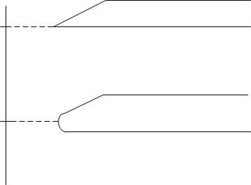
                            A massively exagerated illustration, but if the scriber is blunt, you will scribe a line higher than you wanted to.

                            radiused scriber.jpg

                            Maybe on a blunt scriber it equates to a tenth, a thou, maybe 10 thou I have no idea.

                            Graham


                            Four factors together define how good a measuring instrument is, or not! They are:

                            • Resolution – how finely the instrument's display reads. The display can be a plain scale, a vernier scale, or a digital display. None of them are trustworthy, for example digital calipers usually display to 0.01mm, when they only measure to about 0.02mm. Resolution can be wrong either way : digital displays imply better than reality, and analogue scales suffer multiple error problems, such as parallax,
                            • Accuracy – how close to actuality the measurement is. Unusual for any measurement to be spot on – the result is normally a scatter of answers hopefully near the truth.
                            • Precision – it's common for measurements to cluster together at some distance from the truth, Imagine a gun firing six shots at a bulls eye, and all of them miss but land together a foot to the right. The gun is precise, but not accurate. Conversely inaccurate guns can never be precise.
                            • Repeatability – this is a measure of how close successive measurements are to each other. Expensive digital calipers are often more repeatable than cheaper models of the same accuracy and precision.

                            Height gauges have many limitations. With a microscope, even a sharp scriber is blunt, and so is a new razor blade Even less precise and accurate are the lines scratched by the scriber. A line has to be about 0.1mm (4 thou) wide to be seen with the human eye, and this limits what can be done by scribing. Wouldn't want to make it worse with a blunt rounded scriber, but it's not a major problem.

                            My digital height gauge has the usual screw adjusters, and I expect it's OK to about the same range as a digital caliper, that is ±0.02mm (±1thou). It can pick up a feature to about that, but a scribed line transferred to that height could be 4 times worse.

                            I don't think too much should be expected of a 40 year year old vernier gauge – wear always reduces precision, accuracy, and repeatability. Resolution too, if the scales aren't in good order. Verniers place an additional burden on the operator that causes errors too. They depend on eyesight, correct head position, and brain getting the right answer.

                            How accurate does a height gauge need to be in a home workshop? I think anything that gets within about 0.03mm is 'good enough' unless the owner is doing something special.

                            Plenty of practice needed too. Micrometers come with a clutch to help eliminate pressure errors, but many claim developing a 'feel' is better.

                            Dave

                            Edited By SillyOldDuffer on 05/05/2023 13:28:25

                            #644315
                            Andy Stopford
                            Participant
                              @andystopford50521

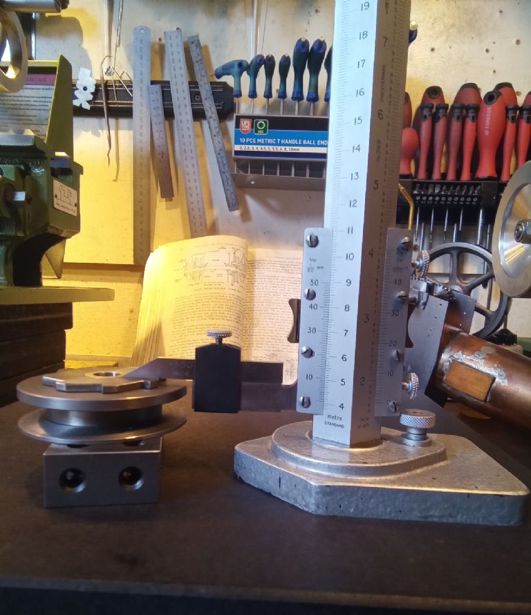
                              This thread (and using the thing this morning) reminded me of something I don't understand about my height gauge, so I took a photo to enquire here:

                              heightgauge.jpg

                              The vernier subdivides each millimetre so you can read to hundredths, but the scale is calibrated 0 to 50, so you have to double whatever the reading is. Why?

                              (The vernier scale is labelled "Ver 1/50mm&quot

                              #644319
                              Baz
                              Participant
                                @baz89810

                                Andy I think you will find it reads 50 x 0.02 which is 1mm. 0.02 of a mm is eight tenths of a thou.

                                #644323
                                Nicholas Farr
                                Participant
                                  @nicholasfarr14254

                                  Hi Andy, Baz is correct, and it means the scale has a resolution of 0.02mm. i. e. 25 Vernier divisions X 0.02 = 0.5mm. Therefore, if you were to make a measurement of 50 + 40 Vernier divisions, it will also = 2"

                                  Regards Nick.

                                  Edited By Nicholas Farr on 07/05/2023 21:00:14

                                  #644324
                                  SillyOldDuffer
                                  Moderator
                                    @sillyoldduffer
                                    Posted by Baz on 07/05/2023 20:21:13:

                                    Andy I think you will find it reads 50 x 0.02 which is 1mm. 0.02 of a mm is eight tenths of a thou.

                                    A good illustration of why I cough up for batteries: a digital readout removes the stress of reading this type of vernier gauge and eliminates interpretation mistakes.

                                    Now then analogue lovers, what height is Andy's gauge reading? And for extra points, what's the thickness of the ratchet-pulley object he's measuring?

                                    Dave

                                    Edited By SillyOldDuffer on 07/05/2023 21:00:27

                                    #644326
                                    Andy Stopford
                                    Participant
                                      @andystopford50521

                                      Yes, but why didn't they just change the numbers on the scale so that they correspond with reality, i.e. the 10 becomes 20 (to be extra helpful, with the tick mark at 5 labelled as 10, etc.), since you have to do that multiplication anyway?

                                      I must admit, a digital one would also save having to look for the appropriate reading glasses (I have recently bought a cheapo digital micrometer for that very reason).

                                      To answer Dave's question, you'll need to know that the 1-2-3 block is a metric 20-40-80…

                                      #644327
                                      Pete Rimmer
                                      Participant
                                        @peterimmer30576

                                        I have a 600mm mitutoyo digital height gauge here with corroded electronics. If anyone fancies that they stand a good chance of repairing it, they are welcome to come and take it for free.

                                        The encoder WAS working, though the plug had been removed and the wires soldered direct to the PCB due to the corrosion mentioned. The battery box is intact but heavily corroded from a past leaked cell which is what I think caused the rest of the corrosion prior to my owning it. The LCD display was hit and miss when I got it, it would come on and then fade out within seconds, or sometimes come on and stay on. It had suffered a couple of repair attempts and now does not come on at all though that is a recent development. It seems the electronics are actually functioning to an extent as the led comes on when the power switch is set to the middle position which I think signifies output to remote display.

                                        Anyway, it's here, it's scrap from my perspective. I'd love to make it work but my electronics knowledge is weak, so if no-one wants to pop along and collect it, it's going in the bin.

                                        It's the same as the one in the link below, except it's in bits and has no scribe or clamp. All of the parts are there for it to be potentially repaired however.

                                        **LINK**

                                        #644330
                                        Nicholas Farr
                                        Participant
                                          @nicholasfarr14254

                                          Hi Andy, as I've said, the resolution is 0.02mm, that means each of the Vernier marks represent 0.02mm, so if you made the 10 into 20 =, that would be 20 X 0.02, which would make it read 0.4mm instead of 0.2mm, so then you would have to divide the 0.4 by two to get the correct answer.

                                          Regards Nick.

                                          #644398
                                          Gareth Thomas
                                          Participant
                                            @gareththomas76772

                                            Thank you for your reply Jason. I am still trying to understand it but I am working on it! it has become clear to me that I could do with some fundamental instruction on how to measure with a height gauge. Is there a web article on it? What I am trying to do is measure hole centre positions on a plate in order that I draw up the item. In my wisdom I thought that by using a 'finger' DTI would give me a more better 'feel' for the bottom of the hole edge and the 'top'? Which would also give the hole dia.. I thought about making dowels to fit the holes then measure the bottom and add half the 'plug' size but that seems a awful long winded method. Any help appreciated.

                                            Gary

                                            #644401
                                            Buffer
                                            Participant
                                              @buffer

                                              Pete. I had a mitutoyo like that with corrosion in the battery box. Some bloke picked it up from an ebay sale and I got 65 quid for it.

                                              #644409
                                              SillyOldDuffer
                                              Moderator
                                                @sillyoldduffer
                                                Posted by Gareth Thomas on 08/05/2023 13:23:00:

                                                … I thought about making dowels to fit the holes then measure the bottom and add half the 'plug' size but that seems a awful long winded method. Any help appreciated.

                                                Gary

                                                That's how I would do it. Hard to measure holes directly.

                                                I don't know of a guide to using height gauges. The principle is straightforward, but as with other precision measuring, technique is vital when accuracy matters, including taking the same measurement several times.

                                                I practised with objects of known size until I got my height gauge to agree repeatedly with reality. As it's hard to judge by feel, I often shine a light behind the pointer to highlight the gap, and/or eyeball it with a loupe.

                                                Digital Readouts are easier – the display is unambiguous, with zero reset and absolute reading, in inches and millimetres. Verniers make my head hurt.

                                                Dave

                                                #644431
                                                peak4
                                                Participant
                                                  @peak4

                                                  Firstly, it's probably easier to search for videos than web articles on how to use your height gauge.

                                                  If I'm reading your requirement correctly;

                                                  How about the following; bear in mind that lever indicators give the best readings when the lever is parallel to the surface being measured.
                                                  I'm assuming you have one of the more conventional DTIs, where there is a lever to change the direction of measurement, rather than a central "both way" indicator needle position.
                                                  To maintain any consistency, you need to use the clock in the same direction each time.

                                                  You seem to have a metric height gauge, so find or make something, which is an exact sensible measurement, say 1 or 2 cm; lets call it 2cm
                                                  Ensure that your workpiece is vertical on your surface plate/flat surface
                                                  Set your height gauge to the thickness/height of your test block i.e. 2cm
                                                  Add the DTI and zero it on your test block height, without adjusting the height gauge.
                                                  Move the workpiece to the height gauge/DTI assembly and adjust the height gauge only for a zero reading for the DTI on the bottom of the hole; you're obviously looking for the lowest point.
                                                  Read and record the height gauge reading; add 2cm and that's the distance to the bottom of the hole from the lower edge of the plate.
                                                  Find a length of round ground bar which fits in the hole, and clamp/wedge it in place at the very top of the hole.
                                                  Now use height gauge/DTI again to measure to the top of the ground bar, this time, you're looking for a maximum reading; read and record the height add 2cm and you have the distance from the top of the hole to the surface plate.

                                                  Subtract the two readings and you have the hole diameter, and can easily calculate its centre.

                                                  It would help to know what other measuring kit you have, e.g. internal micrometers, slip gauges etc. as well as the accuracy you're trying to achieve; also what size roughly is the workpiece.

                                                  Ideally now check your calculations using a different method.

                                                  This is quite a good video on why DTI's are often best used as indicators, rather than for direct measurements (unlike plunger clocks), and why I've described taking all actual measurements off the height gauge.

                                                  Several good points also made in this one, particularly if your surface plate isn't perfect.

                                                  Bill


                                                  Edited By peak4 on 08/05/2023 16:33:21

                                                  #644440
                                                  Andrew Tinsley
                                                  Participant
                                                    @andrewtinsley63637

                                                    Pete,

                                                    I managed to repair exactly the same Mitutoyo height gauge, which had a fair bit of corrosion. It is time consuming and needs a good magnifier, rather than being difficult. Pity to throw it!

                                                    Andrew.

                                                    #644464
                                                    Andy Stopford
                                                    Participant
                                                      @andystopford50521
                                                      Posted by Nicholas Farr on 07/05/2023 21:58:13:

                                                      Hi Andy, as I've said, the resolution is 0.02mm, that means each of the Vernier marks represent 0.02mm, so if you made the 10 into 20 =, that would be 20 X 0.02, which would make it read 0.4mm instead of 0.2mm, so then you would have to divide the 0.4 by two to get the correct answer.

                                                      Regards Nick.

                                                      Hi Nick, perhaps I'm being obtuse here, but if the vernier scale didn't have the "Ver 1/50mm" label, and the numbers ran from 0 to 100, you would simply read it directly, so that in the photo you would get 40mm + the number which lines up on the vernier which would now be 80 rather than 40*, giving the reading of 40.80, no need for mental arithmetic to double the vernier reading (and it would be obvious that each minor graduation was 0.02 since there are five to each 0.1 graduation).

                                                      Its not a huge deal, and I don't use the height gauge often enough to be bothered by it, but it always strikes me as a curious design which unnecessarily increases the risk of error (especially for people like me who are rubbish at mental arithmetic).

                                                    Viewing 25 posts - 26 through 50 (of 53 total)
                                                    • Please log in to reply to this topic. Registering is free and easy using the links on the menu at the top of this page.

                                                    Advert

                                                    Latest Replies

                                                    Home Forums Workshop Techniques Topics

                                                    Viewing 25 topics - 1 through 25 (of 25 total)
                                                    Viewing 25 topics - 1 through 25 (of 25 total)

                                                    View full reply list.

                                                    Advert

                                                    Newsletter Sign-up