Well I wrote all this up like 2 weeks ago then the forum ate it when I pressed create thread so I went off in a huff and procrastinated for 2 weeks before writing it up in word. Lets see how messed up it gets as I transfer from word to the forum.
Also big thanks to Ian for fixing my motor up and showing me how to do this.

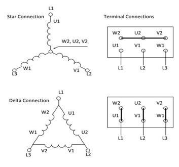
Here is a wiring diagram pulled off the internet showing the different ways to wire a motor terminal. The star connection works on 415V and the delta connection works in 240V. On these diagrams there are 6 terminals on the wiring diagram.

My motor instead had 3 wires poking out the motor itself which were then screwed into the terminal block. This gives us U1, V1 and W1. >>

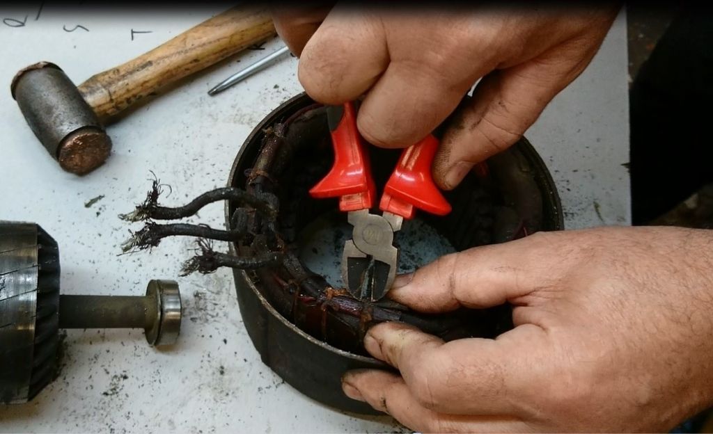
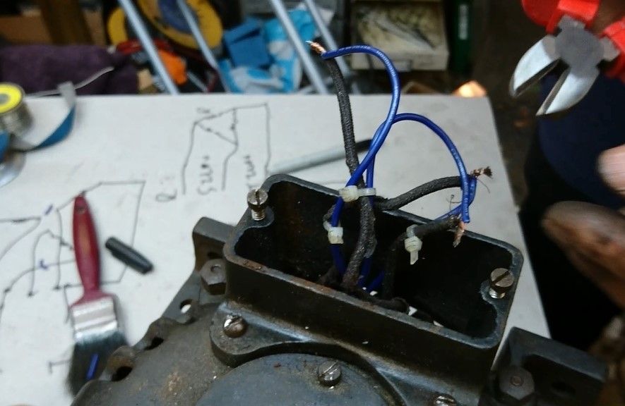
Here the end of the motor has been taken off showing our U1, V1 and W1. Ian is snipping off the cord that ties the wires in place for better access. >>
We have no U2, V2 or W2 though. In our motor diagram above U2, V2 and W2 have been bridged at the terminal but in our actual motor all 3 wires have just been soldered together inside the casing. You need to find the other 3 wires and track down where they are all joined. >>
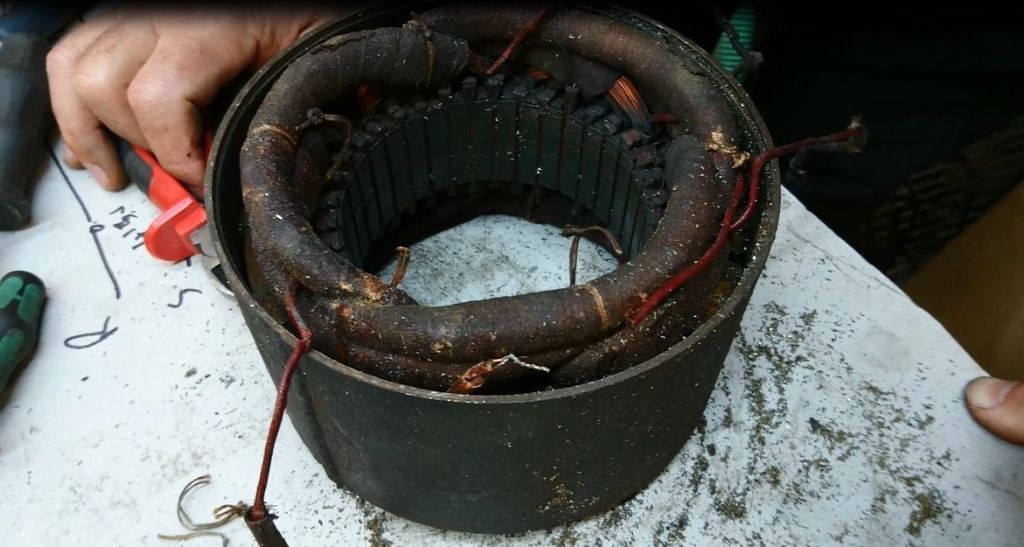
In my motor the wires were well hidden so we found what looked to be a joint on one wire and tore it apart hoping for the best. >>

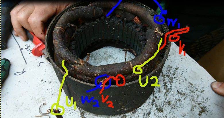
Here is the raw image, you can't really tell what’s going on so here is a professional altered image for clarity.>>

U1, V1 and W1 are just hanging out the motor, we don't care about them. >>
We found the U2 cable and yanked on it, showing us the location of the "star point" where all the "2" wires meet. U2 is sitting off on the right while W2 and V2 and still entwined, both disappearing into the motor housing. >>
You could at this point take out a multi tester and check that none of the wires are broken. If you haven't got 3 pairs of unbroken wire, then I think your motor is toast.>>
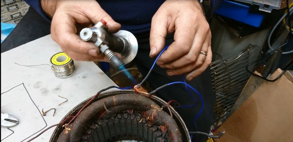
The wires are pretty short right now, not designed to pass out the casing, so we solder an extension onto each wire. Gently sand the end of each wire to get rid of the enamel then solder on an extra length of wire.>>

Here is some heat shrink being fitted over the soldered joints. Look at that nice fresh blue wire.


Rainbows
@rainbows

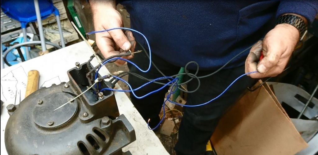
Oh look the motor is back together, might of missed a bit there. Just don’t let the wires get in the way of the studs holding the motor plates together and don’t let anything get caught when it comes together. Here all 6 wires have been brought out into the open air. Ian is testing for continuity with the probes in his hands, and is matching the U1+U2, V1+V2 and W1+W2 wires into pairs. You can see two pairs have been found and ziptied together. Testing the third pair is kind of a unnecessary step but it double checks everything works.

Here is the delta formation being wired up. The old wire from one pair is spliced with the new wire from the next pair. The old wire from the 2nd pair is spliced with the new wire from 3rd pair. The old wire from the 3rd pair is then spliced onto the last new wire on the original pair.

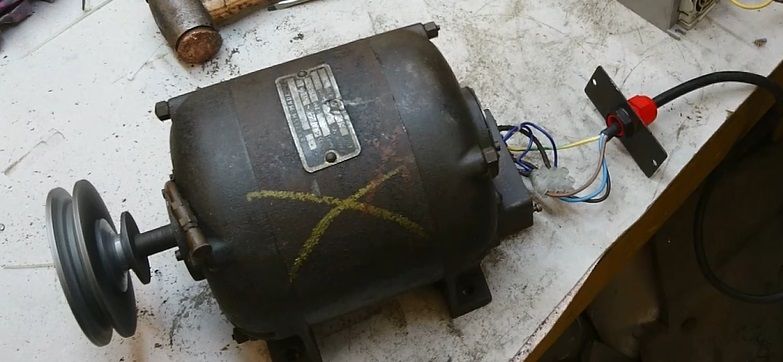
The newly joined wires are stuck into a terminal block and connected to an inverter to check they work.
Originally we had this on a video but we missed out the entire motor reassembly and I think I remember Ian wanting the audio stripped off and replaced with captions and video editing is a lengthy process. Video might come out in the next holiday when I have more time in life.

Rainbows
@rainbows
I don't know if this is just me but I appear to have magically unlocked the new forum layout where everything is very tall and thin

Michael Gilligan
@michaelgilligan61133
No, it's not just you
Your first post appears to be in three column format.
Nevertheless … Thanks for posting it 
MichaelG.

Speedy Builder5
@speedybuilder5
If I understand you correctly, you have converted a 440v 3 phase motor to 240 v 3 phase. I was getting all excited that you had somehow converted a 3 phase motor to a single phase motor.
BobH

Vic
@vic
Posted by Speedy Builder5 on 09/11/2017 10:52:44:
If I understand you correctly, you have converted a 440v 3 phase motor to 240 v 3 phase. I was getting all excited that you had somehow converted a 3 phase motor to a single phase motor.
BobH
I did that with my milling machine. I rewired the connection box from star to delta and added a large capacitor between the live and neutral and it ran on single phase like that for several years before I sold it. You only get about 80% of the motors rated power but I never noticed any difference.

Tony Ray
@tonyray65007
Posted by Rainbows on 09/11/2017 10:20:51:
I don't know if this is just me but I appear to have magically unlocked the new forum layout where everything is very tall and thin
Does it work on people ? – I could do with it

Ady1
@ady1
It's a bit squished and claustrophobic in here isn't it…
Cheers for the post Rainbows

Tim Stevens
@timstevens64731
The only comment I would add is that the six-terminal block shown in these diagrams is also used in many recent single phase machines (in order to confuse the innocent), so please, don't be misled by it. If it runs off an ordinary three pin plug on the wall it is going to be single phase, and voltage changes are not at all easy (or relevant).
Cheers, Tim

Ian Parkin
@ianparkin39383
Might be best to change the title to “how to change 415v only 3 phase motors to dual voltage 3 phase”
Otherwise a good write up thanks G
Ian Parkin.


