How to CAD Model a Welin Interrupted Screw?

Advert

How to CAD Model a Welin Interrupted Screw?

Home Forums CAD – Technical drawing & design How to CAD Model a Welin Interrupted Screw?

Viewing 18 posts - 1 through 18 (of 18 total)
  • Author
    Posts
  • #429677
    SillyOldDuffer
    Moderator
      @sillyoldduffer

      Struck me today that modelling the Welin Interrupted Screw as used on the Vickers Bl 8 inch Howitzer (Mal Webber's build) would be a challenge for a 3D CAD package.

      My attempt with Fusion360 started well but failed at the last hurdle.

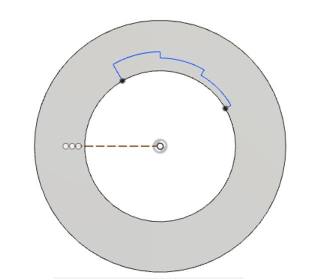
      Step 1: – Create breech ring and mark-out 30degree notches


      welinsteps.jpg

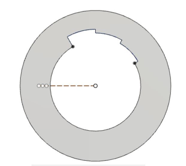
      Step 2 – Pull-cut the slots

      welinstepscut.jpg

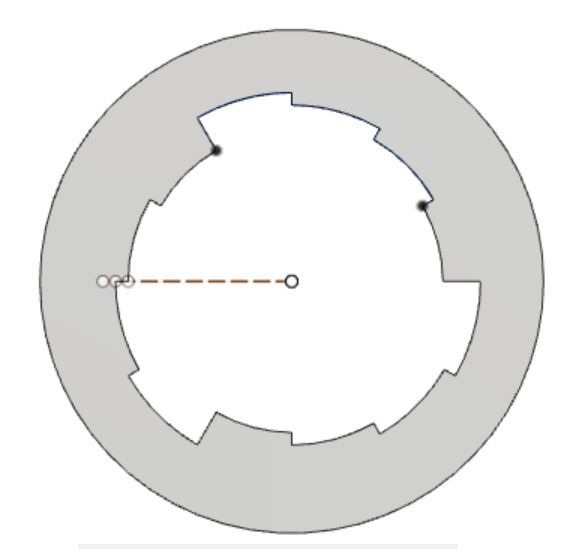
      Step 3 – Multiply slots by 3 with a circular pattern

      welinsteps3cut.jpg

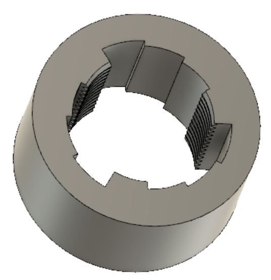
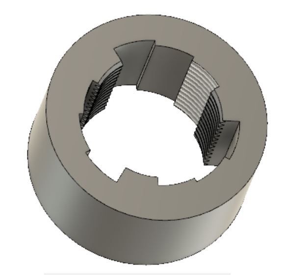
      Step 4 – Model a Real Thread on the innermost surface

      welin1stthread.jpg

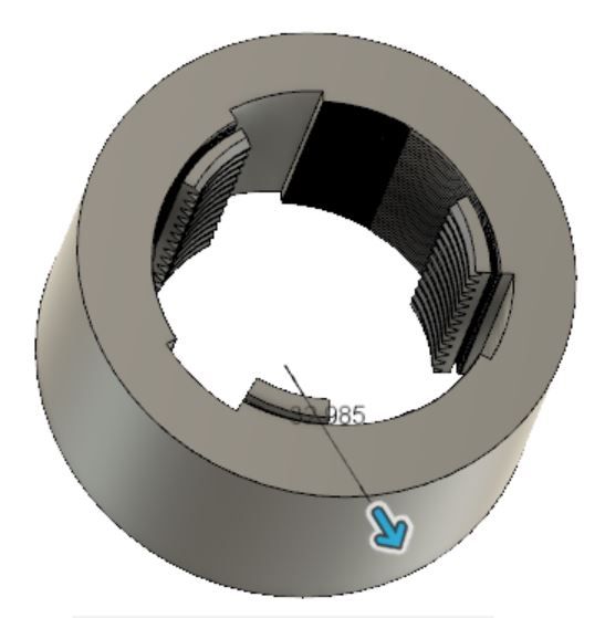
      Step 5 – Model a Visual Thread on the middle ring. (A visual thread is a representation painted on the surface. It would generate g-code, but to save computer time and memory doesn't actually number crunch and add a real thread to the model.

      welin2ndvisual.jpg

      Although it looks promising at Step 5, Fusion breaks when asked to convert the visual thread into a modelled thread.

      Step 6 is mangled!

      welin2ndmodlled.jpg

      Can anyone suggest a way of modelling a stepped interrupted screw thread in F360, or show how it can be done in any other 3D CAD package?

      Ta

      Dave


      Edited By SillyOldDuffer on 19/09/2019 20:53:13

      Advert
      #21292
      SillyOldDuffer
      Moderator
        @sillyoldduffer
        #429679
        JasonB
        Moderator
          @jasonb

          I'd probabaly helical sweep each piece of thread 30deg and then do a circular pattern of the sweep to get the 4 parts, then do the same for the next dia

          That can wait until tomorrow.

          #429747
          Neil Wyatt
          Moderator
            @neilwyatt

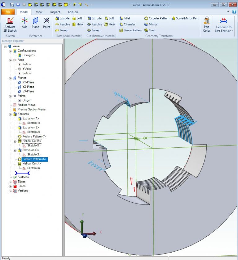
            I would do it this way:

            Extruding the core for a male plug

            Add the segments for the next stage, sweep out the threads.

            Add segments for the final stage and sweep out the threads.

            Internal would essentially be the same but starting with the largest diameter. This may be harder to visualise which is why I described the male version.

            Something like this – the order of parts in the history is important

            welin.jpg


            Edited By Neil Wyatt on 20/09/2019 15:06:48

            #429750
            SillyOldDuffer
            Moderator
              @sillyoldduffer
              Posted by Neil Wyatt on 20/09/2019 14:32:18:

              I would do it this way:

              Model a male thread by extruding a cylinder and then cutting out the threads.

              Add the segments for the next stage, sweep out the threads.

              Add segments for the final stage and sweep out the threads.

              Internal would essentially be the same but starting with teh largest diameter. This may be harder to visualise which is why I described the male version.

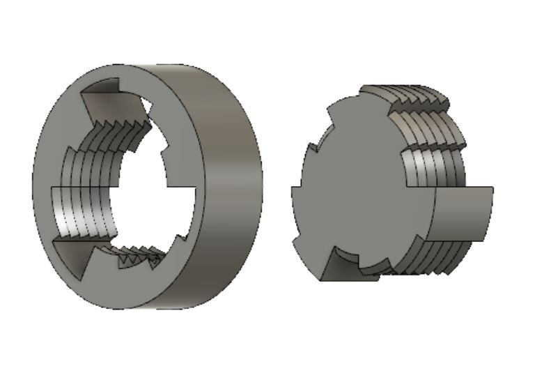
              Thanks Neil, I'll give that a try next. Jasons suggestion works fairly well but the 'threads' produced are straight, rather than screw spiral. (Actually I'm not sure breech threads are spiral cut on a real gun. Maybe they're just locking slots rather than a true interrupted screw. If the obturator provides the gas seal there may be no need to cam the breech into the breech block. Perhaps a trip to Fort Nelson with camera is in order!)

              Dave

              welinjason.jpg

              On the right is an attempt at a breech produced by using a copy of the breech block to cut the outside of a cylinder. Nearly works but I'm having trouble cutting the excess smooth bit off without upsetting the model.

              #429753
              JasonB
              Moderator
                @jasonb

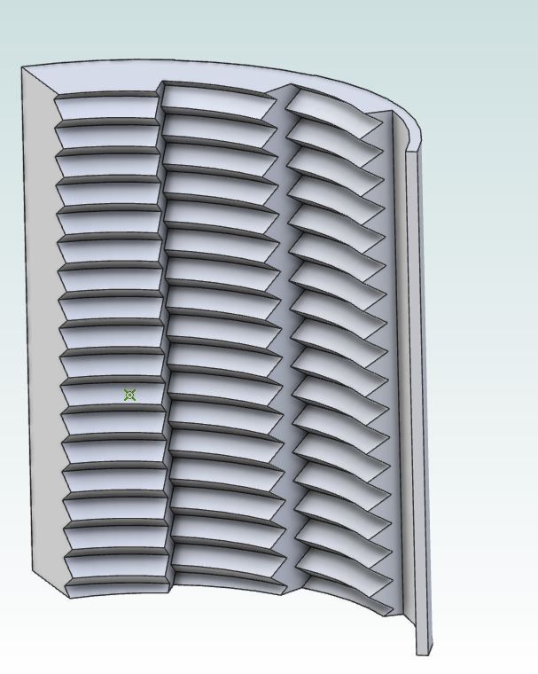
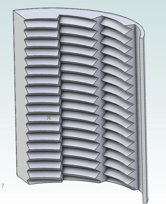
                Mine come out spiral as they are done as a helical extrusion so pitch can be setbreech.jpg

                Shows up more if I double the pitch

                breech2.jpg

                Edited By JasonB on 20/09/2019 15:46:05

                #429757
                Anonymous

                  Darn it, just wasted 20 minutes looking at Youtube. interestingly, as far as I can see the threads are parallel, not helical. Or at least the helix angle is very small. I'd always assumed they were helical.

                  Modelling it shouldn't be too difficult, athough everyone has missed out the grooves between the thread segments. A more interesting question is how one would machine the part. Hint: I suspect the grooves are there not for functionality but to aid machining.

                  Andrew

                  #429762
                  JasonB
                  Moderator
                    @jasonb

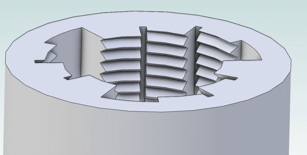
                    Andrew, I was just about to suggest that as Dave has now been able to draw it that his homework for the weekend should be to make itdevil


                    Yes a run out groove for the tooling seems logical

                    breech3.jpg

                    Edited By JasonB on 20/09/2019 16:19:11

                    #429764
                    SillyOldDuffer
                    Moderator
                      @sillyoldduffer

                      Ho hum, just dismantled my Windows laptop for the purpose of identifying the hard-drive and memory for upgrades and am currently stuck on Linux. I'll have to log-out and reboot to get Fusion 360 up to see if it does helical scans. Sounds promising.

                      So far I've only attempted proof of concept models to see if I can produce a breech and breech block that look right. Next step is to make a matching pair that can be jointed to model realistic opening and closing. There's another layer of complexity to come. The breech is turned and swung out on a carrier operated by pulling a lever. First the lever turns the breech to unlock it, then hits a stop causing the motion to transfer to swing the breech out and away from the breech ring. Various ways of doing this of which the Asbury mechanism ended up as favourite. But screw breech guns seem to have used several different mechanisms, and I've not found a good drawing of any of them! As Asbury was invented in the US in 1916 it's unlikely Mel's 1917 British Howitzer uses it.

                      I guess a machine tool was made specially to cut these threads, perhaps an attachment on the giant lathe used to turn and bore the barrel. I imagine a single point tool on a lathe that only turns 30° per cut and reciprocates on cams, with a very short lead-screw to add pitch. As a machine tool it's more complicated than a plain screw-cutting lathe and must have been a challenge to design itself. Clever geezers those old boys!

                      Dave

                      #429765
                      Mick B1
                      Participant
                        @mickb1
                        Posted by Andrew Johnston on 20/09/2019 16:02:11:

                        Darn it, just wasted 20 minutes looking at Youtube. interestingly, as far as I can see the threads are parallel, not helical. Or at least the helix angle is very small. I'd always assumed they were helical.

                        Modelling it shouldn't be too difficult, athough everyone has missed out the grooves between the thread segments. A more interesting question is how one would machine the part. Hint: I suspect the grooves are there not for functionality but to aid machining.

                        Andrew

                        'Strewth, I think you're right and I never knew that before!

                        In this clip from Sink The Bismarck, you can see the gun-loading process from about 0:16 to about 1:00. HMS Vanguard's gun mountings are representing the catastrophically-fated Hood's, but they were very similar. You can see that the breech plug doesn't appear to retract or advance in the opening or closing rotations.

                        Denmark Strait

                        #429778
                        Neil Wyatt
                        Moderator
                          @neilwyatt
                          Posted by Andrew Johnston on 20/09/2019 16:02:11:

                          Darn it, just wasted 20 minutes looking at Youtube. interestingly, as far as I can see the threads are parallel, not helical. Or at least the helix angle is very small. I'd always assumed they were helical.

                          Modelling it shouldn't be too difficult, athough everyone has missed out the grooves between the thread segments. A more interesting question is how one would machine the part. Hint: I suspect the grooves are there not for functionality but to aid machining.

                          Andrew

                          That's interesting! Actually easier to model with a helix as you only need to draw one tooth and extrude it.

                          #429779
                          Neil Wyatt
                          Moderator
                            @neilwyatt
                            Posted by SillyOldDuffer on 20/09/2019 16:32:28:

                            Ho hum, just dismantled my Windows laptop for the purpose of identifying the hard-drive and memory for upgrades and am currently stuck on Linux. I'll have to log-out and reboot to get Fusion 360 up to see if it does helical scans. Sounds promising.

                            So far I've only attempted proof of concept models to see if I can produce a breech and breech block that look right. Next step is to make a matching pair that can be jointed to model realistic opening and closing. There's another layer of complexity to come. The breech is turned and swung out on a carrier operated by pulling a lever. First the lever turns the breech to unlock it, then hits a stop causing the motion to transfer to swing the breech out and away from the breech ring. Various ways of doing this of which the Asbury mechanism ended up as favourite. But screw breech guns seem to have used several different mechanisms, and I've not found a good drawing of any of them! As Asbury was invented in the US in 1916 it's unlikely Mel's 1917 British Howitzer uses it.

                            I guess a machine tool was made specially to cut these threads, perhaps an attachment on the giant lathe used to turn and bore the barrel. I imagine a single point tool on a lathe that only turns 30° per cut and reciprocates on cams, with a very short lead-screw to add pitch. As a machine tool it's more complicated than a plain screw-cutting lathe and must have been a challenge to design itself. Clever geezers those old boys!

                            Dave

                            Note that the real thing often had some clearance on it to allow it to swing closed in a more compact arrangement.

                            Neil

                            #429786
                            old mart
                            Participant
                              @oldmart

                              I would guess that those threads were produced on a rotary shaper, if such a tool ever existed.

                              #429787
                              Michael Gilligan
                              Participant
                                @michaelgilligan61133

                                Drawing it is way out of my league … but Chapter IV of this may be of interest: **LINK**

                                https://archive.org/details/textbookordnanc00acadgoog/page/n106

                                MichaelG.

                                #429824
                                Anonymous

                                  From the link provided by MG it appears that the Welin breech is indeed a screw thread on a helix. Since it is a relatively fine thread and a large diameter the helix angle is small and thus difficult to see. For instance a 1/2" pitch thread of 15" diameter has a helix angle of only 0.6 degrees. I'd been worried about saying the thread was parallel. One of the functions of the breech is to provide a gas tight seal and I didn't see how it could do that without a small axial movement as a thread was tightened.

                                  I've been reading a thread on "practicalmachinist" and I think SoD has it. The consensus was that the thread was single pointed in the conventional way, but with the addition of a cam on the cross slide that stepped it between three pre-determined positions as the work rotated. The slots between threads are to allow the cross slide time to move.

                                  I'm almost tempted to have a go at modelling and making one just for the hell of it. Although I'd use the rotary table on the CNC mill as a sort of vertical lathe rather than mess about with cams.

                                  Andrew

                                  #429832
                                  duncan webster 1
                                  Participant
                                    @duncanwebster1

                                    There is a lot of stuff on here about how they were made, and a suggestion that as well as being stepped they were tapered

                                    **LINK**

                                    Edited By duncan webster on 21/09/2019 00:19:17

                                    #429837
                                    JasonB
                                    Moderator
                                      @jasonb

                                      I noticed the taper in Michael's link too.

                                      #429842
                                      Michael Gilligan
                                      Participant
                                        @michaelgilligan61133
                                        Posted by Andrew Johnston on 20/09/2019 22:28:10:

                                        [ … ]

                                        I've been reading a thread on "practicalmachinist" and I think SoD has it. The consensus was that the thread was single pointed in the conventional way, but with the addition of a cam on the cross slide that stepped it between three pre-determined positions as the work rotated. The slots between threads are to allow the cross slide time to move.

                                        [ … ]

                                        .

                                        I saw mention, somewhere, of a Geneva Stop Mechanism

                                        Horology meets Armaments smiley

                                        MichaelG.

                                        .

                                        Ref. Lots of diagrams and animations available on the web

                                        … but here is a decent analysis:

                                        https://www.researchgate.net/publication/319666064_Kinematic_Analysis_and_Design_of_a_Geneva_Stop_Mechanism_Teaching_Aid_for_Intermittent_Motion

                                        … and the Watchmaker's variant:

                                        https://watchmaking.weebly.com/geneva-stop-work.html

                                        Edited By Michael Gilligan on 21/09/2019 07:50:56

                                        Edited By Michael Gilligan on 21/09/2019 08:05:31

                                      Viewing 18 posts - 1 through 18 (of 18 total)
                                      • Please log in to reply to this topic. Registering is free and easy using the links on the menu at the top of this page.

                                      Advert

                                      Latest Replies

                                      Viewing 25 topics - 1 through 25 (of 25 total)
                                      Viewing 25 topics - 1 through 25 (of 25 total)

                                      View full reply list.

                                      Advert

                                      Newsletter Sign-up