How on earth do I build this boiler for my Fire King ?

Advert

How on earth do I build this boiler for my Fire King ?

Home Forums Beginners questions How on earth do I build this boiler for my Fire King ?

Viewing 25 posts - 1 through 25 (of 25 total)
  • Author
    Posts
  • #536802
    Bob Wild
    Participant
      @bobwild67557

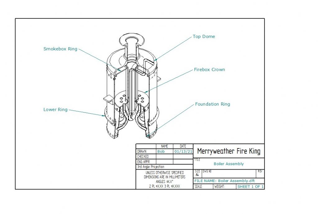
      Here is an assembly drawing for my boiler:

      boiler assembly.jpg

      There are many features which frighten me:

      1. All the various rings are supposed to be rivetted. Surely I must solder all the parts to make them steam tight?
      2. The rings are supposed to be copper, but I can't find any supplier of solid material that size (approx 4in dia). But I have found a foundry that can cast them in brass. Would that material be OK, if the price is right?
      3. What is the best way to make the conical inner part. Should I start with a piece of tube with the same diameter as the smaller section and bash it up a former. Or should I start with a tube the same as the larger diameter and try to spin it down? Or should I even prefabricate it from sheet wrapped round a former and soldered at the seam?
      4. There is a pipe in the centre called the "Steam Supply Pipe" (is this a superheater pipe?) which has a 180 deg bend. This pipe is 6mm OD with a 4mm inside radius. How on earth can you bend this?
      5. Finally, and this is the scary bit, how am I going to solder it all together? Do I need different melting point silver solder, and in what order should I try to assemble it?
      6. I've just read a biography of Cherry Hill in which it explains that all her beautiful models were built to run on air only. If that was good enough for her, then it could be for me as well. In which case I could leave out most of the internal parts and simplify things enormously, let alone worry about making it steam tight.

      Any advice from those more experienced than me would be most appreciated.

      Bob

      Advert
      #10774
      Bob Wild
      Participant
        @bobwild67557
        #536807
        Simon Collier
        Participant
          @simoncollier74340

          I would roll the conical firebox section from sheet. I would roll the rings from copper bar. Brass is unacceptable. Yes all rivets must be sealed with silver solder. You could use copper elbows for the tight bends. I have used 1/4 elbows with 1/4 pipe. As for the order of assembly, I would have to stare at a bigger diagram for a while to decide.

          Using the lowest temperature available throughout would be easiest. If the joints do not have too big gaps, it is not a disaster if they melt again in subsequent heats so long as they are fluxed first. If the gaps are too big, the solder might flow out of the joint and this is a drama. Close sliding fits only, no more. If you are not experienced, do lots of test joints.

          Just my personal opinion but I hate to see models built to run on air only. It defeats the whole purpose of a steam engine, with the smoke, coal and smell being the main appeal, but your model, your choice.

          #536809
          duncan webster 1
          Participant
            @duncanwebster1

            Don't use brass in a boiler, you could get de-zincification. The only ring as such looks to be the foundation ring, you can make this by bending rectangular copper bar, butt joint the ends. All the rest are flanged plates. I wouldn't bother with the joint in the shell. You'd be well advised to join a ME club and discuss it with the boiler inspector. Last thing you want to do is silver solder it all up then find you can't get it approved. For the tapered firebox you have three options, cheat and make it parallel (which is what I'd do), cut a wedge out of a tube, close it up and fit a but strap, or roll a cone, this mmost difficult involving cutting out an odd shaped profile, rolling it to shape a fit a but strap. Unless you want a forest of rivets only use as many as needed to hold it together for silver soldering, if it's not there it can't leak

            Edited By duncan webster on 29/03/2021 00:18:35

            #536813
            Nigel Graham 2
            Participant
              @nigelgraham2

              For a start I would not make as complicated as that – for one thing you don't need those water-tubes in the firebox on a model. Nor do you need copy the original, bolted-together design (which I think is hidden under the cladding anyway.)

              For the next I would strongly advise, if you have not already done this, buying books on miniature boiler-making and silver-soldering. have a look in the Tee Publishing lists, particularly the Workshop Practice series. They tend to concentrate on locomotive-type boilers but the fabrication methods are all much the same.

              Then (we've not even gone into the workshop yet )…

              That drawing looks as if copied from a diagram of the original, which was designed for very rapid steam-raising to suit its purpose. Simply scaling full-size boilers in detail to small model size rarely works well, so some compromises are necessary for assembly methods and indeed actually making steam. So, prepare new drawings of the boiler in miniature, to normal model-engineering boiler practice, but fairly representing the original externally. Take especial note of dimensions, for a matter I will come to…

              '

              Why do you need those rings? Copying the full-size, with the 2-part boiler shell bolted together? That complicates things, but anyway, if you are going to build the fire-engine around the boiler, they would be hidden by the lagging.

              If you do still want them, you are best making them as dummies to represent the prototype, but having no contact with the inside of the boiler. You would have to cut them from plate, and flange them by the normal methods in making miniature copper boilers. They could be soldered to the shell with a fairly-high melting-point soft solder, since they are not doing anything structural. Don't use through-fastenings to the shell, for them.

              The rings were riveted on the originals, yes, but these were steel shells whose riveted joints were fullered and caulked steam-tight. Rivets are used in model boilers normally either as stays or as assembly-aids, and in both cases are silver-soldered along with the main jointing anyway.

              If you fit those dummy bolting-flanges you could use brass sheet; but do not use brass on the internal surfaces of a boiler where it is exposed to high-temperature water and steam, as it is likely to decompose (the zinc dissolves out of the alloy, I don't claim to know the chemistry).

              '

              That firebox is probably more easily cylindrical with little or no effect on performance; but it will need to be of fairly thick wall because a cylinder (and presumably, truncated cone) is much weaker under external than internal pressure.

              A reasonably deep crown-plate flange inside the firebox shell will add to the hoop-strength; that central flue, fitted in an outwards-flange in the crown-plate, will act as a longitudinal stay.

              You might find copper tube of appropriate diameter for it and indeed for the shell, with some compromises on scale to suit what is available. Otherwise it's rolled shell and lap-plated, silver-soldered joint. Though if you want you could roll it the firebox conical without much more difficulty – after all, some locomotive boiler have tapered boiler barrels often copied in miniature.

              '

              That pipe inside the flue is a super-heater. In full-size they had room to form it like that, but in a model you would almost certainly have to make a return-bend to join two lengths of pipe. The usual, in model locomotives, is a "spear-point" of or bronze, with two holes at converging angles to take the ends of the tubes; held in with high-melting-point silver-solder.

              '

              Order of assembly: the firebox and flue unit, assemble that into the outer shell which has already had its various bushes or mounting-pads for the fittings, then the foundation-ring and top tube (or flue) -plate.

              Note that " then the foundation… " .

              Because…

              The fly in the cutting-fluid here, is the major detail you have not shown: the fire-hole. I know the, Merryweather boiler because a friend used one for a freelance narrow-gauge loco, and on that example and as far as I know all Merryweather boilers, the firehole is in the side. So it has to pass through the water-space round the firebox.

              I must admit I had to think hard, but this is how I see it:

              The fire-hole is a short tube of length is the width of the water-wall at the chord formed where it penetrates the wall, plus the sum of the two plate thicknesses. You would have to draw it out, because all its circumference has to penetrate fully, both walls.

              However, it also constrained by the assembly; hence my point above, about drawings.

              Size the innards so when the fire-hole tube has been soldered into the firebox, that assembly, with the flue, will slide into the boiler barrel with the foundation-ring not yet fitted.

              Move it across the shell so the firehole tube can poke through its hole in the shell.

              Then fit the foundation-ring and top-plate, ensure all aligned correctly, and silver-solder them together.

              '

              You don't really say how big this is, but you will need different melting-point silver-solders for the different parts, and you will need put a lot of heat into the metal as rapidly as possible.

              Everything needs drawing first, dimensioned carefully, so that it can be fitted together.

              '

              Or just run the model on air… I think fully-working Merryweather steam fire-engines have been made, so it's feasible. You need translate full-size boiler-making to its model-engineering version.

              #536824
              JasonB
              Moderator
                @jasonb

                The design is dated and construction methods have changed

                1. Silver Solder will be the order of the day.

                2. If by rings you mean the flanged plates then flange them front copper sheet. Foundation ring bent up from square/rectangular section. Top dome can be brass spun or cast as it is just a cover. "Tee Ring" soldered up from two pieces with a high temp solder

                3. Conical parts rolled

                4. The bent pipe will act as a superheater

                5. Carefully and suggest you try something smaller to get your hand in.

                6. If you don't intend to steam it then just build an empty shell.

                Any changes except No 6 run by your boiler inspector first. Also if using Julius drawings then treat these as an untested design and get them approved first as his boilers often leave something to be desired.

                Edited By JasonB on 29/03/2021 07:53:15

                #536831
                JasonB
                Moderator
                  @jasonb

                  Original ME article for those interested

                  As said a simpler design from 4" tube with a tube for the firebox and some simple cross tubes would make life easier and give a running engine. Add the skirt and bottom flange as dummies for looks, rivit detail can also be done as dummy ones if wanted.

                  #536885
                  Nigel Graham 2
                  Participant
                    @nigelgraham2

                    I agree, Jason, much the best to adapt a proven, published miniature boiler design and modern model-boiler practices.

                    However, I don't think Bob's primary mistake is of the construction being "outdated", except for using rivets structurally. (I am pretty sure you can, under the current boiler code, still make and test a riveted and solder-caulked boiler for a small, low-pressure engine; but it is probably more difficult than straight silver-soldering.)

                    Rather, I think he was misled by a diagram of the full-size boiler, into thinking the model needs fully replicate its rather involved internals and two-part shell.

                    '

                    Building a miniature Merryweather boiler to its own design though in copper and hard-soldered, with those water-tubes and bolted-together shell, would be interesting and feasible, but perhaps not as a first attempt. The hardest part would be setting the two major joint sets correctly and squarely apart.

                    (One bolted joint is the obvious band round the shell, low down. The other is less visible, studs and nuts round the flue, and hidden by the top dome. On my friend's full-size specimen I helped dismantle and re-assemble, the two joints had quite thick gaskets to take up any irregularities; and I believe the boilder-inspector recommended the material. Its shallow dome was of sheet-steel I think, spun or pressed, with brass trim.)

                    A fully-replicated model version might also give some clubs' boiler-admirers the heebie-jeebies as being of a design unfamiliar to them!

                    #536903
                    JasonB
                    Moderator
                      @jasonb

                      Nigel, the copper boiler does not use bolted construction, the flange at the top of the "skirt" is a dummy and flue is soldered to tubeplate. The 3" STEEL boiler to Haining's design does have the bolted flange above the skirt and also around the flue that you mention as well as 43 cross tubes for good measure!

                      Although not a fan of Julius boiler drawings his 3D images do make it a bit easier to see what's going on and he has not departed too much from the ME design, drawing scan be downloaded from part way down this page it's the 1908 engine.

                      #536925
                      Keith Hale
                      Participant
                        @keithhale68713

                        Hi Bob,

                        Before worrying about the brazing and soldering operations, create your build program. In what order will you produce your components for assembly.

                        Does this involve multiple brazing or soldering operations? There are three readily available alloys with different melting ranges to facilitate this. Your supplier should be able to guide you through this.

                        Good advice has already been offered in suggesting you improve your knowledge by getting one of the books available via Tee Publishing (including mine!) This will enable you the best materials.to ask the pertinent questions questions of your suppliers to get.

                        Then you can consider how you are going to stick them together. You will learn about the joint designs and heating techniques to ensure our you are successful and avoid leaks and the subsequent repairs!

                        Rivetted assemblies seldom benefit from silver solder. Joint strength is provided by the rivet. If you only require a seal, there are considerably cheaper and easier ways to achieve that than silver solder.

                        By the time you get round to sticking bits together, you will have invested a lot of time and money. This is not the time to find out that if you had done something slightly differently things would be easier easier at the later stages.

                        Regards

                        Keith

                        #536930
                        Weary
                        Participant
                          @weary

                          On the same page that Jason linked to above with the drawings (link here again for convenience), there is also a link to a build description, here. It is immediately to the right of the drawings' link.

                          The build is described in French, however the photo's are international, and even if you don't speak French an on-line translator and some imagination will assist & maybe clarify. The boiler is described and pictured on the lower part of page 2 of the build description.

                          Bonne chance!

                          Phil

                          #536936
                          Jeff Dayman
                          Participant
                            @jeffdayman43397

                            Bob, Mr Werner Schleidt in Germany has built the Fire King and has several videos of it running well posted on this site. Maybe you could contact him and ask about his boiler's construction / which plans he used / materials. He has done one, and would have recommendations I am sure.

                            #536956
                            JasonB
                            Moderator
                              @jasonb
                              Posted by Weary on 29/03/2021 16:42:51:

                              On the same page that Jason linked to above with the drawings (link here again for convenience), there is also a link to a build description, here. It is immediately to the right of the drawings' link.

                              The build is described in French, however the photo's are international, and even if you don't speak French an on-line translator and some imagination will assist & maybe clarify. The boiler is described and pictured on the lower part of page 2 of the build description.

                              Bonne chance!

                              Phil

                              Looks like that boiler has a brass foundation ring and a very narrow brass strip inside the joint where skirt meets upper boiler barrel. All best avoidedsad Flanging of the firebox top plate looks like it will leave some excess gaps that will make for a poor solder joint too.

                              #537117
                              Bob Wild
                              Participant
                                @bobwild67557

                                Chaps, thanks for so many constructive and detailed points. I think the general consensus is that it could be simplified' I have had a few thoughts about this and will post a sketch shortly. I do have a few specific queries:

                                Nigel – what is a fire hole tube? The design shows a spirit burner mounted directly below the boiler. A bit more iinfo on the spear point would help.

                                Jason – How do you fasten dummy rivets to the copper tube. I like this idea.

                                Keith – I looked up "Keith Hale" on Amazon books,

                                I have been in touch with Gege in France who has bee most helpful, and also Werner in Germany.

                                Having read up about the Fire King it seems that the boiler was not lagged. Another interesting fact is that the total time for working pressure to get underway was about 6 minutes!

                                Bob

                                Edited By JasonB on 31/03/2021 07:08:35

                                #537126
                                JasonB
                                Moderator
                                  @jasonb

                                  Fire hole tube is a tube or sleeve that you put the coal into the boiler through, it needs to pass through both skins of the lower part of the boiler but is not shown on your drawings due to the use of gas firing, dummy door could be fitted. Have a look at this one

                                  Will post about rivits later.

                                  #537150
                                  Keith Hale
                                  Participant
                                    @keithhale68713

                                    Hi Bob.

                                    There are three sources for my book. Amazon is not one.

                                    Good luck with your project.

                                    Keith

                                    Edited By JasonB on 31/03/2021 06:54:40

                                    #537209
                                    JasonB
                                    Moderator
                                      @jasonb

                                      Back to the Rivits, as you have not done much boiler work I would suggest avoiding drilling into the water space to fit them so.

                                      Top row that would have gone through the smoke box tube plate or ring as it is called on your drawing. I would either make the boiler shell a little taller or lower the tubeplate so that the rivits can be fitted through the single skin of the outer tube. They don't need fully setting just cut them slightly over length, one tap to expand them enough so they don't fall out and then solder them in and file off flush internally

                                      For the flange that would have originally joined the tapered skirt to the vertical barrel and assuming the skirt will now be a decorative add on then flange an "L" section ring, fit rivits to the vertical leg of the ring as above and then solder the ring to the outside of the barrel at an early stage. This does put the "l" on the outside but I think that the safest method but see below.

                                      Form the tapered skirt form that with a "washer" sodered on so you have two flanges that can use bolts to joint the two together, ring of rivits as before just below the flange.

                                      Boiler. Do away with all the bent small tubes and have 3 or 4 cross tubes through the top of the firebox which will make better use of the heat before it goes up the central flue.

                                      Or more radical change would be to get rid of the water space around the firebox in which case the skirt can now be bolted on to act as the firebox. Then change from single flue to multi tube boiler which will increase heating area to compensate for that lost around the firebox. in which case the lower flange "L" section can fit inside as per original.

                                      #537362
                                      Bob Wild
                                      Participant
                                        @bobwild67557

                                        Thanks Jason, this is all getting very interesting. I like the idea of a separate ring to take the rivets. In fact I have some round headed ba screws with no slot. I could use these and they would look just like rivets.

                                        I can certainly increase the height of the shell to increase the separation of the top dome and smokebox ring.

                                        I am considering doing away with the cone shape on the outer lower ring which would mean I could just extend the whole outer shell down to the bottom of the boiler. And as you suggest I could use an L shaped ring to hold some dummy rivets.

                                        If I increase the angle of the inner cone I can make it butt join directly with the outer shell. I don't mind not having any rivets at the base since this is right at the bottom of the boiler and right out of sight.

                                        I can get rid of the 12 bent fire tubes and replace them with a couple of pairs horizontally across the top of the fire box.

                                        Not sure if Cherry Hill would approve of all these changes, but what the heck. I am starting to draw this out (slowly).

                                        Incidentally I have spoken with Gégé and he tells me he did use a gas burner in the end. I presume this also will give a higher heat output than the spirit version. He also said he made the conical parts by wrapping a sheet round a former and the soldering the seam. I would have preferred to use a tube the same diameter as the small end, and then try and swage it up a former. Any thoughts?

                                        Bob

                                        #537371
                                        Nigel Graham 2
                                        Participant
                                          @nigelgraham2

                                          Jason –

                                          (A few posts back) I was not assuming Bob's engine would use a bolted-together boiler, in fact I advised against it; though I did muse on the possibility as a general point.

                                          (I'd considered it for my own project, which is copper, though with a steel ring on both external faces of the flanges to spread the bolt loads and prevent buckling.)

                                          '

                                          Bob –

                                          Sorry, I didn't know you'd intended spirit firing; maybe now gas.

                                          My first reply was early on when the only information I could see was that part-sectioned GA apparently based on the full-size, but not showing how it was to be fuelled. It was somewhat natural for me to assume coal or other solid fuel, and simply omitting the grate and ash-pan on a drawing of a boiler's structure alone would not have alerted me to alternatives.

                                          Those slot-less screws are indeed made to be pretend rivets!

                                          Increasing the hem of the firebox (the 'inner cone' ) enough to join it directly to the outer shell, dispensing with an intervening foundation-ring, is in fact similar to the practice used by some manufacturers of full-sized boilers.

                                          Horizontal cross-tubes in the firebox is again a common approach.

                                          Swaging a tube to that cone is feasible, but as it thins the metal, don't start with a wall already very thin.

                                          Looking again at your heading drawing, it seems to overcome the problem of forming the return-bend in the super-heater by making it of Omega-shape, with the advantage of not needing joints in it; but that does place the loop in the firebox. I am not sure if that would be wise as it would probably be in the flame.

                                          #537539
                                          Bob Wild
                                          Participant
                                            @bobwild67557

                                            Thanks Nigel. More good ideas.
                                            Bob

                                            #538689
                                            Bob Wild
                                            Participant
                                              @bobwild67557

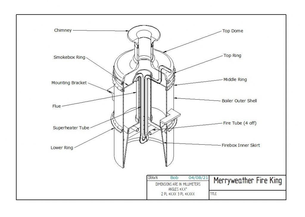
                                              boiler assembly v1.jpg

                                              Here's a drawing of the modified boiler, taking account the various suggestions I've received. The changes are :

                                              1. I have done away with the outer conical section and extended the boiler outer shell to the bottom of the boiler.
                                              2. The twelve curved fire tubes have been replaced by 2 pairs of straight tubes fitted directly across the firebox, each pair being at 90 deg to the other.
                                              3. The firebox inner skirt now meets the outer shell so it may be soldered directly to it.
                                              4. All the rivets have been replaced by dome headed screws fastened to three new rings. These are labelled Top, Middle and Lower Ring. These new rings can be soldered directly to the outer shell, so there will be no holes into the boiler.
                                              5. Question: What about doing away with the top ring and screwing the Boiler Outer Shell and Top Dome directly? There is no water or steam in this region only the exhaust gases.

                                              Any thoughts about these changes? One immediate benefit that I can see is that I only need one casting. Although the foundry I found quoted quite a reasonable price and fairly quick delivery. Apparently he gets quite a few similar requests from model locomotive builders. I am thinking that I may need to use different melting point solders and build it in stages. Any advice would be most appreciated.

                                              By the way the boiler is 4in dia and overall height is 10 in.

                                              Bob

                                              Edited By Bob Wild on 08/04/2021 17:10:37

                                              #538703
                                              duncan webster 1
                                              Participant
                                                @duncanwebster1

                                                I'd make the shell from 4" 16g and the firebox from 3.5" 16g. Then you roll a ring from 3/16" square to make up the gap, a lot easier than making the conical firebox

                                                #538713
                                                Jeff Dayman
                                                Participant
                                                  @jeffdayman43397

                                                  Just my opinion Bob, but I don't think having the firebox inner and outer shell meet at a sharp junction with no foundation ring is a good idea. Depending on the water you use, there may be a lot of sediment buildup at the lower end of the boiler. If it is a small space tapering to a point, it will fill quickly and you may get plate overheating if there isn't water between the shell and firebox inner because the space is full of sediment. A foundation ring provides a) a water space to keep plates cool / transfer heat, b) a wide ledge for sediment to fall on, and be shifted / blown off during blowdown. Food for thought.

                                                  Edited By Jeff Dayman on 08/04/2021 19:31:49

                                                  #538783
                                                  Nigel Graham 2
                                                  Participant
                                                    @nigelgraham2

                                                    Yes – your modifications all looks good, but I note Jeff's observation on taking the firebox wall out to the shell, without a foundation-ring. Looking at your second drawing the annulus is finely-tapered and as Jeff says, could silt or scale up quite easily. Thinking about it further, the full-size boilers made without a foundation-ring had a step formed round the firebox shell so the water-space stayed wide for its full depth.

                                                    If the fuel is to be spirit or better, gas, you are not going to need to open the smoke-box very often, but if the rings will be prominent, visible features on the finished model, then fit them even though dummies. .Faithful external details, even if not functional in miniature, greatly enhance the complete model.

                                                    #542810
                                                    Bob Wild
                                                    Participant
                                                      @bobwild67557

                                                      Thanks chaps for all your useful comments, and sorry about the delay in replying. SWMBO insisted on using the relaxing of lockdown to use the opportunity to go off in our caravan for a much needed break. Anyway, I have made a strategic decision which may not meet with the approval of some. This model will only run on air. Firstly, it makes the construction simpler and secondly, it means that I can show it in my display cabinet along with my other models. As I said earlier, if it was good enough for Cherry Hill then it’s good enough for me.

                                                      Bob

                                                    Viewing 25 posts - 1 through 25 (of 25 total)
                                                    • Please log in to reply to this topic. Registering is free and easy using the links on the menu at the top of this page.

                                                    Advert

                                                    Latest Replies

                                                    Home Forums Beginners questions Topics

                                                    Viewing 25 topics - 1 through 25 (of 25 total)
                                                    Viewing 25 topics - 1 through 25 (of 25 total)

                                                    View full reply list.

                                                    Advert

                                                    Newsletter Sign-up