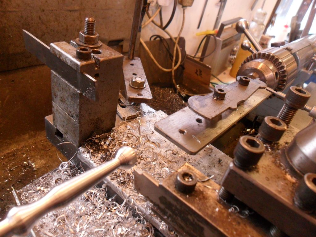
How could I make this curved conrod?

Advert

How could I make this curved conrod?

Home Forums Workshop Techniques How could I make this curved conrod?

Viewing 8 posts - 51 through 58 (of 58 total)
  • Author
    Posts
  • #320858
    Bodger Brian
    Participant
      @bodgerbrian
      Posted by Raglan Littlejohn on 08/10/2017 14:34:53:

      Image result for lathe profile template dti follower

      Another picture of Nobby's method. The cross slide stays engaged, just follow the template with the dti using the crosslide handle. The only work involved is cutting out the template and mounting it in the tailstock chuck.

      I'm being very dim here & my poor beginner's brain is trying to understand this. Am I right in thinking that the phrase 'follow the template with the dti' means that the idea is to maintain a constant reading as it's plunger moves in & out?

      Brian

      Advert
      #320863
      JasonB
      Moderator
        @jasonb

        Yes, its a bit like those fairground attractions where you have the loop on a stick and try to follow a bendy wire!

        Edited By JasonB on 10/10/2017 13:32:23

        #320864
        Bodger Brian
        Participant
          @bodgerbrian

          Thanks Jason – I like the analogy.

          That's what I assumed but thought it best to check before I file the technique away in my brain for possible future use.

          Brian

          #320888
          Anonymous
            Posted by duncan webster on 09/10/2017 14:19:43:

            I've read both of those in the digital archive, they tell you how to use it but not the intricacies of how they work. Having a hydraulic valve that will follow a profile and move the tool to the thou is quite something.

            I didn't want to get too technical in the original article. wink 2

            In principle the operation is quite simple, although it requires some accurate machining. High pressure oil from the pump reaches the unit and is directed to the front face of the ram. Some oil is also supplied, via a couple of holes, to a bobbin connected to the guide mechanism. This bobbin is such that on one side there is a slight leakage onto the back face of the ram, and from there a leak on the other side of the bobbin back to the tank. The clever bit is that the front face of the ram is arranged to have exactly half the surface area of the back face. So the system will be in balance when half the oil pressure is dropped at the front edge of the control bobbin, and the other half at the back edge. If the bobbin is moved slightly by the guide this unbalances the pressure drops at either side of the bobbin and the ram will move so as to equalise the pressure drops again.

            Andrew

            #321475
            duncan webster 1
            Participant
              @duncanwebster1

              Thanks for that, I now understand. What we now need is for some clever person (not me!) to design a second topslide with stepper motor drive and a sensitive LVDT to track the profile give a poor man's version. Would be whizzo for turning wheels and fancy con rods etc. I suppose it could run off Mach3 if there were sensors on the leadscrew.

              #321486
              Clive Foster
              Participant
                @clivefoster55965

                Duncan

                Thats the hard way of doing it!

                These days just draw a line in some suitable computer program convert it to a suitably scaled set of X-Y co-ordinates in single stepper motor or encoder step units and have at it. Either steppers on both cross and longitudinal traverse or just sit an encoder on the longitudinal feed and use the existing power feed. Probably prudent to drive the stepper via a perfect lost steps compensator so if it does miss a beat there is never more than one step error on both axes.

                Never understood the lost step hoo-ha in hobby CNC machines as I put such a perfect compensator in a "£100 IR Homing system" tech demonstrator way back in the late 1970's. Had to be simple and cheap and had to work as the flight control system re-defined hairy! Shoulda kept my notes.

                If its complicated an you have the original just take a suitably lit picture and process to extract the edge line.

                Clive.

                #321490
                Jon Cameron
                Participant
                  @joncameron26580

                  I have read the various ways of doing the curved con rod. Well done to Dave for seeing it through a second time to make a nice one that follows design.

                  I can't offer any other way of doing it to the radius, though for me I think I would deviate from design and buy an adjustable tailstock centre for this purpose. Then turn the taper on one side reverse the con rod and machine the taper on the other, finishing with some emery to loose the straight edges a little.

                  But thats just me, always go against convention.

                  #321500
                  duncan webster 1
                  Participant
                    @duncanwebster1

                    Clive,

                    If you only have x axis under control and the y axis is been driven at constant speed by the leadscew you can't have faces at anything like 90 degrees to the long axis. With a powered topslide set at 45 degrees if you retract it at root 2 * the y axis speed you get the tool point coming out at 90 dgrees, ie not advancing in y direction even thought the saddle is advancing. However you're right that it wouldn't need a second topslide, could use the one that's there

                  Viewing 8 posts - 51 through 58 (of 58 total)
                  • Please log in to reply to this topic. Registering is free and easy using the links on the menu at the top of this page.

                  Advert

                  Latest Replies

                  Home Forums Workshop Techniques Topics

                  Viewing 25 topics - 1 through 25 (of 25 total)
                  Viewing 25 topics - 1 through 25 (of 25 total)

                  View full reply list.

                  Advert

                  Newsletter Sign-up