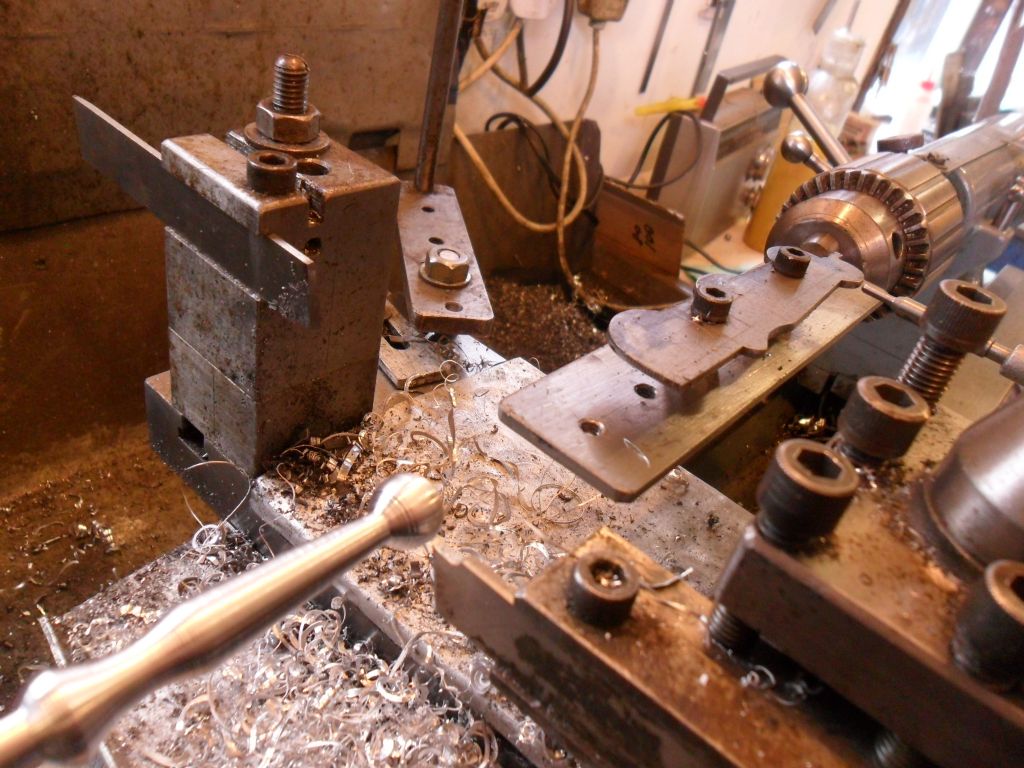
How could I make this curved conrod?

Advert

How could I make this curved conrod?

Home Forums Workshop Techniques How could I make this curved conrod?

Viewing 25 posts - 26 through 50 (of 58 total)
  • Author
    Posts
  • #320526
    SillyOldDuffer
    Moderator
      @sillyoldduffer
      Posted by Andrew Johnston on 08/10/2017 14:00:46:

      Posted by SillyOldDuffer on 08/10/2017 11:35:28:

      Neil highlighted a problem with perfectionism. Inspector Meticulous would not be satisfied with just an R300 fish belly: he would insist on sharp ends as well! The more I look at problems like this the more I appreciate what goes into exhibition standard work.

      Any Inspector Meticulous worth his salt would sack the designer for creating a poorly engineered and difficult to make part with no fillets. wink 2

      Andrew

      It does make me wonder how many designers fail to think about difficulty of making the thing. Or of maintaining it! Most of the cars I've owned had difficult to reach fasteners, some much worse than others. After failing to get a water pump off I took it to a garage. 'How will you do that?' I asked. 'It's impossible – you have to take the engine out' he replied. Most of the bill was labour costs plus VAT…

      Advert
      #320528
      Raglan Littlejohn
      Participant
        @raglanlittlejohn

        Image result for lathe profile template dti follower

        Another picture of Nobby's method. The cross slide stays engaged, just follow the template with the dti using the crosslide handle. The only work involved is cutting out the template and mounting it in the tailstock chuck.

        #320542
        Nobby
        Participant
          @nobby

          Hi Raglan
          Thank you for posting this photo of my method . I found works quite well
          Nobby

          #320546
          Raglan Littlejohn
          Participant
            @raglanlittlejohn

            Hi Nobby,

            Thanks for that. I thought that picture might help to show how quick it is to set up.

            #320550
            duncan webster 1
            Participant
              @duncanwebster1

              For the benefit of those of us who don't know how a hydraulic copy attachment works (apart from it copies a profile by some magic means), how about someone writing an article for Neil?

              #320552
              JasonB
              Moderator
                @jasonb

                I thought Andrew had already done an article on the copy attachment.

                #320554
                Anonymous
                  Posted by JasonB on 08/10/2017 16:57:20:

                  I thought Andrew had already done an article on the copy attachment.

                  Phew, saves me blowing my own trumpet. embarrassed

                  MEW 167 September 2010 – Fitting and Using a Hydraulic Copying Unit

                  MEW 256 July 2017 – Making a Valve Rod Coupler (uses the hydraulic copying unit)

                  Andrew

                  #320559
                  SillyOldDuffer
                  Moderator
                    @sillyoldduffer
                    Posted by Raglan Littlejohn on 08/10/2017 14:34:53:

                    Image result for lathe profile template dti follower

                    Another picture of Nobby's method. The cross slide stays engaged, just follow the template with the dti using the crosslide handle. The only work involved is cutting out the template and mounting it in the tailstock chuck.

                    Thanks from me too – I'd jumped to the conclusion that Nobby's method was complicated because the cross-screw has to be disconnected. Wrong again! Actually, now I've finally 'got it', following a template in the tail-stock should be very easy to do. I particularly like that templates can be used to create copies, useful for example when building a multi-cylinder engine. I shall have a serious play with Nobby's method tomorrow.

                    Cheers,

                    Dave

                    #320571
                    Harold Hall 1
                    Participant
                      @haroldhall1

                      Useful things Spreadsheets.

                      Whilst having no relevance to machining a barrel shaped conrod some may be interested in the use I eventually put the spread sheet to that I developed for the task.

                      I had decided to make a dining table and felt that a slightly curved edge, lengthwise, would add some character to the outcome. The usual method of a piece of string anchored at one end and a pencil at the other was not practical as the string needed to be far too long. I then realised that the spreadsheet I had produced for the conrod could be used. From the result I produced a template for using with a hand held router. Having developed it for a radius of around 400mm it was then used to provide the coordinates for a curvature of about 25Mtrs, values from memory.

                      Should anyone like to see the end result its on my website here. **LINK**

                      Harold

                      #320579
                      Sam Longley 1
                      Participant
                        @samlongley1

                        Cannot imagine any of my joiners using a spreadsheet normally just 2 nails & a bent batten did the job

                        #320591
                        Harold Hall 1
                        Participant
                          @haroldhall1

                          That's an interesting idea Sam. but then, I have not been a cabinet maker as a trade. Will though consider it should I have the need again, though unlikely. In any case, the spreadsheet already existed so it came to my rescue. Incidentally, neither was I a metalworker, but working as an electrical systems design engineer in large power, multi motor projects. In any case, for me, working out a method to achieve something is part of the pleasure in making something, even if its not the best method.

                          Harold

                          #320594
                          ega
                          Participant
                            @ega
                            Posted by Harold Hall 1 on 08/10/2017 21:38:30:

                            … In any case, for me, working out a method to achieve something is part of the pleasure in making something, even if its not the best method.

                            Harold

                            Hear, hear!

                            #320647
                            Sam Longley 1
                            Participant
                              @samlongley1
                              Posted by Harold Hall 1 on 08/10/2017 21:38:30:

                              That's an interesting idea Sam. but then, I have not been a cabinet maker as a trade. Will though consider it should I have the need again, though unlikely. In any case, the spreadsheet already existed so it came to my rescue. Incidentally, neither was I a metalworker, but working as an electrical systems design engineer in large power, multi motor projects. In any case, for me, working out a method to achieve something is part of the pleasure in making something, even if its not the best method.

                              Harold

                              Harold

                              There is absolutely nothing wrong with doing it the way you did it & you have clearly achieved your aims with perfection. However, if one imagines an absolute beginner following your comment & then wondering how to set up & work the spreadsheet then setting it out do you not feel that he/she would be put off at the first hurdle.

                              if he knew that he could do the job in 90 seconds with greater accuracy with a simple tool do you not feel that he would be more likely to proceed.

                              I sometimes wonder about some of the things I read on this forum. As an example I read about forumites using Fusion to draw stuff first then make it & I get lost at just trying to get a free copy of fusion let alone using it. Then I begin to loose interest in the project before I even start.

                              I know that is a wild example but can you not see what I am saying. As a beginner I want to know the easiest way not the most complicated way known to mankind.

                              Once I can do it then i will look at ways of refining the process & getting perfection. For now I just want to make something that at least works !!!

                              so 2 pins & a bit of batten it would be- worked for my father & grandfather

                              Now I wait to get slaughtered !!!!!!!

                              Edited By Sam Longley 1 on 09/10/2017 08:29:20

                              #320663
                              Michael Gilligan
                              Participant
                                @michaelgilligan61133
                                Posted by Sam Longley 1 on 09/10/2017 08:27:19:

                                so 2 pins & a bit of batten it would be- worked for my father & grandfather

                                Now I wait to get slaughtered !!!!!!!

                                .

                                Sam,

                                What you describe is, I believe, dignified by the term 'spline' … and it provides a geometrically elegant solution, requiring no hard sums !! … That's good engineering in my book.

                                MichaelG.

                                .

                                P.S. … It does not produce a segment of a circle; but something much more sophisticated [and also very appropriate to the con-rod situatin]

                                Edit: For reference https://en.m.wikipedia.org/wiki/Spline_(mathematics)

                                … Skip foorward to the 'History' paragraph.


                                Edited By Michael Gilligan on 09/10/2017 09:45:55

                                Edited By Michael Gilligan on 09/10/2017 10:11:20

                                #320667
                                ega
                                Participant
                                  @ega

                                  From Ernest Joyce's Funiture Making:

                                  "For the drawing of long sinuous or continuous curves a spline made from thin plywood, cut so that the grain of the outer skin lies across the width of the spline, is indispensable. It is a two-man job to use it."

                                  Perhaps father and grandfather did it together!

                                  This addresses the point that the "batten" needs to bend evenly if geometric accuracy is needed.

                                  #320676
                                  JasonB
                                  Moderator
                                    @jasonb

                                    I tend to keep a couple of thin strips cut from the edge of a sheet of MDF as it is consistant so you get an even bend. I manage OK on my own, bit of hot melt glue will tack the batten in place so you can run a shallow groove with a laminate trimmer, then bandsaw down the middle of the groove and finally cut to the edge of the groove with a flush trimming bit.

                                    I also use CAD for getting a set of co-ordinates, did an oval table top that way recently so there is a good reason to draw it out first. Plus the fact that most joinery works of a reasonable size these days will have a good size overhead CNC router which will cut any radius be it constant or variable.

                                    If you have a decent DRO on your lathe you can use that to generate the cuts for a 300mm radius, just tell it the centre position if about a foot away from the lathe axis when you use the ARC function.

                                    Edited By JasonB on 09/10/2017 10:26:04

                                    #320693
                                    SillyOldDuffer
                                    Moderator
                                      @sillyoldduffer
                                      Posted by Sam Longley 1 on 09/10/2017 08:27:19:

                                      Posted by Harold Hall 1 on 08/10/2017 21:38:30:

                                      However, if one imagines an absolute beginner following your comment & then wondering how to set up & work the spreadsheet then setting it out do you not feel that he/she would be put off at the first hurdle.

                                      if he knew that he could do the job in 90 seconds with greater accuracy with a simple tool do you not feel that he would be more likely to proceed.

                                      I sometimes wonder about some of the things I read on this forum. As an example I read about forumites using Fusion to draw stuff first then make it & I get lost at just trying to get a free copy of fusion let alone using it. Then I begin to loose interest in the project before I even start.

                                      I know that is a wild example but can you not see what I am saying. As a beginner I want to know the easiest way not the most complicated way known to mankind.

                                      Once I can do it then i will look at ways of refining the process & getting perfection. For now I just want to make something that at least works !!!

                                      so 2 pins & a bit of batten it would be- worked for my father & grandfather

                                      Now I wait to get slaughtered !!!!!!!

                                      Edited By Sam Longley 1 on 09/10/2017 08:29:20

                                      I think Sam has a very valid point of view – simple is best. Or at least as Einstein said: 'as simple as possible, but no simpler'.

                                      Trouble is what people think of as 'simple' depends on who you are. Most of us are not cabinet makers! On the other hand, I expect anyone coming to the hobby aged 55 or under will be familiar with spreadsheets, and quite a few who are older. I first used one in 1984.

                                      I know a little about splines because I'm interested in the history of shipbuilding. The form of ship and boat hulls often have to curve in three directions. Laying out was done full-size in a Moulding Loft, hence Lofting.

                                      Boats and Wooden ship parts were made direct from the spline curves chalked on the floor. Steel and Iron parts were made by referencing wooden templates taken from the floor markings.

                                      There are a couple of disadvantages in using splines in this way. One is that a hull form derived from an eye-balled spline curve may not be optimum for speed or economy. More serious was the cost of scaling the method up as the size and complexity of ships increased. The spline, tacks and chalk are all dirt cheap. The Mould Loft is not, nor is translating the plan into physical reality. Later, optimising the form of Aircraft and rockets became a step too far for manual splines, and mathematics started to take over. Once you're into mathematical solutions computers become essential. Once computers are involved it's logical to start modelling designs. That has many advantages not least opening the door to more efficient production methods.

                                      Computers in a home-workshop? Depends entirely what you're doing. I think they're just another tool.

                                      Sam mentioned the difficulty of downloading Fusion360. Very true, I found it confusing. You can download the free version from here. That gives you a 30 day trial. When the trial period expires, it asks if you want to renew for another free year. After that there's no guarantee that the product will be free forever but – so far – it's stayed free for amateur use. Professional users are expected to pay for a license.

                                      Dave

                                      #320720
                                      duncan webster 1
                                      Participant
                                        @duncanwebster1
                                        Posted by Andrew Johnston on 08/10/2017 17:17:28:

                                        Posted by JasonB on 08/10/2017 16:57:20:

                                        I thought Andrew had already done an article on the copy attachment.

                                        Phew, saves me blowing my own trumpet. embarrassed

                                        MEW 167 September 2010 – Fitting and Using a Hydraulic Copying Unit

                                        MEW 256 July 2017 – Making a Valve Rod Coupler (uses the hydraulic copying unit)

                                        Andrew

                                        I've read both of those in the digital archive, they tell you how to use it but not the intricacies of how they work. Having a hydraulic valve that will follow a profile and move the tool to the thou is quite something.

                                        #320748
                                        SillyOldDuffer
                                        Moderator
                                          @sillyoldduffer

                                          Reporting back, success with cutting to calculated curve coordinates followed by blending. The radius is closer to 295 than 300mm but I blame operator error for that.

                                          dsc04583.jpg

                                          I'd be a smug bar-steward except I spoiled the part during roughing out.

                                          dsc04584.jpg

                                          Now, do I put the mangled con-rod in the engine flawed side down in the hope that no-one notices, or do I start again and do it properly? Ho-hum…

                                          Dave


                                          Edited By SillyOldDuffer on 09/10/2017 18:01:45

                                          #320750
                                          Howard Lewis
                                          Participant
                                            @howardlewis46836

                                            Maybe I'm over cautious, but in my book, the pock marks in the pin end, would make it scrap for a running engine, because the sharp corners would be stress raisers liable to result in a fatigue fracture.

                                            Blending away the metal around the notches will weaken the eye appreciably, so to my mind, not on, for a runner.

                                            To horrify everyone, if it is to be purely a show piece, you could hide the errors underneath, and agonise all the way into the future!

                                            As the late Peter Robinson, said, once, in jest, " If you can't make it right, make it bright". But he never seemed to make it wrong!

                                            Howard

                                            #320756
                                            Harold Hall 1
                                            Participant
                                              @haroldhall1

                                              I would like to explain that my first post was just to show how I used the spread sheet for the barrel shaped conrod to get me out of a problem, being how to produce a very slight curve, lengthwise, on the edge of a dining table.

                                              Having produced curved edges on around 6 items of furniture I have always used my pencil on a length of string method with the centre point of the curve, often found by trial and error.

                                              In the case of the table the distance to the centre point was too far away for that to be practical within the workshop, or even the garden. I did consider doing it out in the road (not so silly. we live almost at the end of a dead end road) with my wife standing on the end of the string and me drawing the curve further down the road. I was concerned though that the string maybe caught on rough patches making it impractical.

                                              It was then that I remembered the spread sheet and realised that it would overcome the problem perfectly. I posted my comments, not to say this is how it should be done but how I got out of a problem using a spreadsheet set up for a quite different task.

                                              I agree Sam, that over complication can put off a beginner but for me the method I used for the conrod seemed simpler than other methods, such as using a template and follower. One cannot all the time produce methods that suit the novice metalworker, even me who is considered good at helping them along.

                                              Incidentally, Jason, I also suggested using CAD as an alternative to obtain the coordinates for producing a barrel shaped conrod. Like the chair, very nice!

                                              Harold

                                              The easiest way of doing something can still be difficult.


                                              Edited By Harold Hall 1 on 09/10/2017 20:07:57

                                              #320757
                                              Anonymous
                                                Posted by SillyOldDuffer on 09/10/2017 18:01:14:

                                                Reporting back, success with cutting to calculated curve coordinates followed by blending. The radius is closer to 295 than 300mm but I blame operator error for that.

                                                dsc04583.jpg

                                                Looking good, but is it a trick of the light that it looks trapezoidal rather than circular? May be little more work with files about a third, and two thirds, along?

                                                If it were me I'd swallow hard, bin it, and make another one. On the plus side it won't take nearly as long. And as I know to my cost some members of this forum seem to have an unerring eye for mistakes when one shows parts. sad

                                                Andrew

                                                #320764
                                                duncan webster 1
                                                Participant
                                                  @duncanwebster1
                                                  Posted by Howard Lewis on 09/10/2017 18:56:59:

                                                  Maybe I'm over cautious, but in my book, the pock marks in the pin end, would make it scrap for a running engine, because the sharp corners would be stress raisers liable to result in a fatigue fracture.

                                                  Blending away the metal around the notches will weaken the eye appreciably, so to my mind, not on, for a runner.

                                                  To horrify everyone, if it is to be purely a show piece, you could hide the errors underneath, and agonise all the way into the future!

                                                  As the late Peter Robinson, said, once, in jest, " If you can't make it right, make it bright". But he never seemed to make it wrong!

                                                  Howard

                                                  The stress raiser caused by that little crescent shaped gouge will be as nothing compared to the stress raiser where the rod bit meets the eye with no or very little radius. The section through the eye has a lot more area than the end of the rod for starters. If it were mine I'd just fill it with cellulose putty or similar and give it a coat of paint.

                                                  #320768
                                                  SillyOldDuffer
                                                  Moderator
                                                    @sillyoldduffer
                                                    Posted by Andrew Johnston on 09/10/2017 19:49:49:

                                                    Posted by SillyOldDuffer on 09/10/2017 18:01:14:

                                                    Looking good, but is it a trick of the light that it looks trapezoidal rather than circular? …

                                                    If it were me I'd swallow hard, bin it, and make another one. On the plus side it won't take nearly as long. And as I know to my cost some members of this forum seem to have an unerring eye for mistakes when one shows parts. sad

                                                    Andrew

                                                    After all that fuss making it d**n*d thing it looks trapezoidal in the picture. Doh!

                                                    Fortunately it's OK in real life; I think the effect is probably due to me tilting the camera.

                                                    I think you and Howard are right though – it has to be done again. I can't deny I need more practice. Much more!

                                                    Dave

                                                    #320776
                                                    Anonymous
                                                      Posted by SillyOldDuffer on 09/10/2017 20:43:23:

                                                      After all that fuss making it d**n*d thing it looks trapezoidal in the picture. Doh!

                                                      Fortunately it's OK in real life; I think the effect is probably due to me tilting the camera.

                                                      That's a relief; possibly shadows?

                                                      Practice makes perfect, or so they say; didn't work for me. Better, but definitely not perfect. smile

                                                      Andrew

                                                    Viewing 25 posts - 26 through 50 (of 58 total)
                                                    • Please log in to reply to this topic. Registering is free and easy using the links on the menu at the top of this page.

                                                    Advert

                                                    Latest Replies

                                                    Home Forums Workshop Techniques Topics

                                                    Viewing 25 topics - 1 through 25 (of 25 total)
                                                    Viewing 25 topics - 1 through 25 (of 25 total)

                                                    View full reply list.

                                                    Advert

                                                    Newsletter Sign-up