Hot air and stirling engines

Advert

Hot air and stirling engines

Home Forums Beginners questions Hot air and stirling engines

Viewing 25 posts - 201 through 225 (of 457 total)
  • Author
    Posts
  • #46278
    Ian S C
    Participant
      @iansc

      Gordon W my best(second built) is horizontal,its in one of Marks photos,its based on James G.Rizzo’s Dyna it has 1 3/4″ bore,it has a camper stove burner.A more efficient type is a ring burner that surrounds the hot end,but I’v only used these on vertical engines with the hot end at the top.The engine with the copper gauze lined chimney sounds interesting,must see if I can find out anything about it.Ian S C

      Advert
      #46293
      Mark Smith 3
      Participant
        @marksmith3
        Ian, My son suggested trying a shop that deals in radio control cars,etc. for the bearings you need. As for holding bearings firmly, a good trick is to drill say a con rod slightly smaller than the bearing and with a junior hack saw inserted in the hole cut a slit down the shank 10mm. This allows the bearing to be pressed in without stress; but I must confess to having used loctite on occasion when the drilling didn’t go well.
         
        Gordon, looking forward to a pic of your motor when you get it finished. The engine you mentioned sounds interesting, but I too am conflumoxed by the copper gauze lining.
        Mark
        #46321
        Ian S C
        Participant
          @iansc

          Mark I,v got most of the bearings,but the one for the crank I bought today at SMP Bearings in Carlyle st,cost $NZ11.Its a 6mm needle roller,goes in a 10mm hole,its 9mm long.got a new bearing for the milling machine,it took nearly 10 min to fit and get going.I’v used the slot cutting method,I,v also drilled through the conrod,through the slit and put a little bolt to close the hole firmly on the bearing.Went to Smiths,no bearings,went to George Henerys they have a number of sizes,the smaller 3 sizes $NZ7-20 ea.Ian S C

          Edited By Ian S C on 17/12/2009 12:26:11

          #46326
          Gordon W
          Participant
            @gordonw
            Hi, the motor I’m starting is loosly based on one from an old mag. on tnet, Amateur Work from about 1920 at a guess (sounds like old german rock band), this has 2 1/2″ power bore x 3″ stroke, said to be suitable to drive sewing machine or small lathe ! Mine’s about 30% biggerall round so should be good for ploughing. Will post picture when !-finished, 2- got a camera 3- figure out how to do it.
            #46339
            Mark Smith 3
            Participant
              @marksmith3
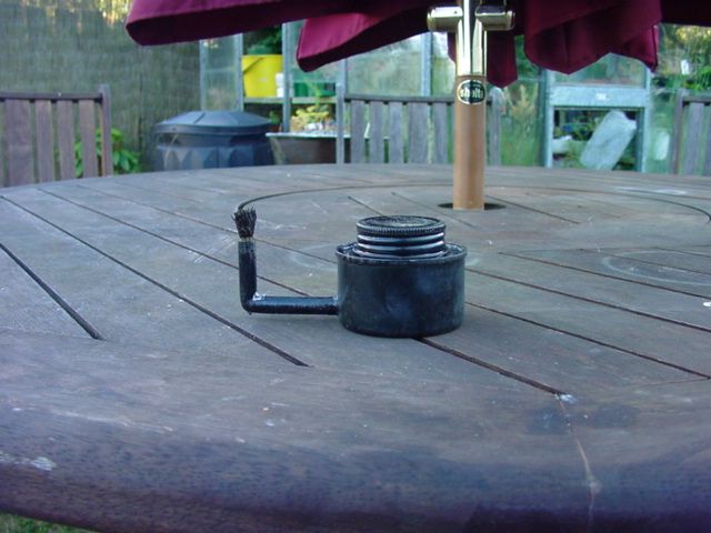
              Grand nephew’sengine is now running happlily on meths. I didn’t actually change anything just waited a day and away it went first flick after warm up – they seem to do that. The burner is finished made from a small salmon tin and the top from a solvent tin soldered in. 8mm elbow tube solder at the bottom and my usual fibre glass wick – it works well.
              Bearings are a reasonble price aren’t they.
              #46375
              Ian S C
              Participant
                @iansc

                If a first it won’t go,wait a while,then sneak up and take it by supprise,you got to get them when they least expect it.The milling machine is going well,did an hr or so this evening.Ian S C

                #46425
                Mark Smith 3
                Participant
                  @marksmith3
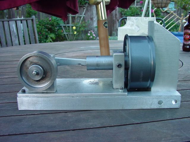
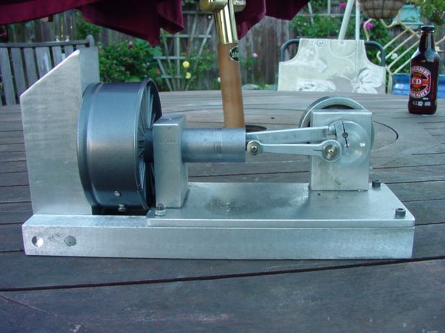
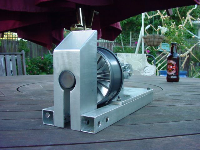
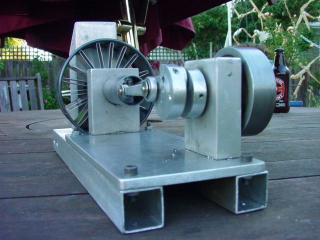
                  Here are a couple of pics of The Devon, my grand nephews engine, nearly finished. I just need to make a base, fit a generator, and a safe box to house it. As you can see it is a Beta and features a cooling unit made from junk parts namely, a heat sink from a computer joined and bent round into a fan. The shroud is a baking ring for pavlova. I got the idea for the stack from one of Roy Darlington’s marine engines. Specs are 25mm bore, 20mm stroke, displacer stroke 30mm. The cylinder is one piece held in the frame with a cap screw, this makes adjustments easy as well as simple to disassemble if required. All the rods and shafts have ball bearings from hard drives and features an aluminium piston with my usual leather cup seal and teflon stuffing box to seal the displacer shaft. It starts easily once warm and runs at a good speed ( can’t measure that yet).
                   
                  Maybe I can now get on with solving the problems with my big pressurised engine…unless another nephew or grandson……….

                  #46438
                  Ian S C
                  Participant
                    @iansc

                    Hi Mark,that looks good,with a tank that size it’ll run for ages.You’d just about fit the generatorunder the con rods,just in front of the cylinder.I see that the bearing I got for the milling machine cost $nz9-50 less GST.The boss said it might be quite expensive!My budget for repairs was $nz50,so that leaves me $40-50 for something else.Ian S C

                    #46625
                    Peter Fleming 1
                    Participant
                      @peterfleming1
                      Can anyone suggest either a kit, or comprehensive plans (preferably the former) of a quality Stirling engine that looks good? A very dear friend has a fascination with driving steam locomotives (full size) and is retiring from work shortly. We both work for the same company, which we both agree runs on “hot air” and I thought this would be an ideal retirement gift for him; a bit of a play on words
                       
                      Many of the kits I’ve seen I’m sure work just fine, but aren’t exactly something I would present to somebody for 40 years service. I have a lathe only workshop and would like to use the opportunity to refine my own skills, though I’m not out for a massive “challenge” so the easier to produce the better. I don’t know much about stirling engines but the image of what I’m looking to produce might have some form of beam in the engine (though not essential), spoked flywheel, and enough brass to be able to polish parts up to a high finish so it looks like a presentation piece. In short it should “look” like an engine and sot some sort of scientific experiment. Oh and it should work!
                       
                      Any suggestions?
                       
                      Pete 

                      Edit: I prefer to work in metric if possible

                      Edited By Peter Fleming 1 on 25/12/2009 00:36:02

                      #46638
                      Mark Smith 3
                      Participant
                        @marksmith3
                        Hi Pete try this site http://cgi.ebay.co.uk/ws/eBayISAPI.dll?ViewItem&item=160380845916 it has lots of brass, a beam, and spoked flywheel by the look of the pic.
                        Or try this one http://www.ministeam.com/acatalog/Bohm_Stirling_Engines_and_Kits.html it looks a bit scientific but has all the elements you want.

                        Mark

                        Edited By Mark Smith 3 on 25/12/2009 19:54:19

                        #46641
                        Peter Fleming 1
                        Participant
                          @peterfleming1
                          Thanks Mark, I’ve gone through all the ones available on ebay and ruled them out. The one you pointed out in particular, you’d be happy presenting something that looked like that??? The thing was cheap and nasty and had a piece of plastic for a “flywheel”.
                           
                          The second link I hadn’t seen before, but from what I can understand all the pieces are pre-machined so not at all what I was asking about. They were quite expensive too.
                           
                          Again, the prerequisites I’m looking for are: it should look like an engine, not a scientific experiment; actually function; look like a beautiful piece of art/trophy that you would present to somebody as an honour; be machined (at least partially) by myself; be metric (preferably).
                           
                          If nothing comes up I may revisit some of the ebay offerings and see if I could use them as a basis for the core engine but modify some of the ancillary components to make them visually more appealing. I’m trying to avoid having to spend ages chasing after miniscule quantities of stock and supplies that I might not normally have/use, hence the attraction of a kit.
                           
                          Pete 
                           
                          PS It doesn’t even have to be a Stirling engine, I just thought that would be the easiest option. Any other very simple engine design would be fine too. 

                          Edited By Peter Fleming 1 on 25/12/2009 21:54:34

                          #46643
                          Martin W
                          Participant
                            @martinw
                            Peter
                             
                            Try looking on the Grizzly machinery site as they do kits and have plans in pdf format that could be useful, well possibly.
                             
                            The address is http://grizzly.com/products/Horizontal-Stirling-Engine-Kit/H8101 the plans actually give you dimensions and materials the only thing that is not covered fully, as it is supplied, are full details of the hot cylinder and piston plus the cold/operating piston otherwise it is fairly complete. There was one exhibited at the Sandown show in a highly polished state which looked quite nice but was not oily enough for me!!!!!
                             
                            Hope this helps
                             
                            Cheers
                             
                            Martin W
                            #46644
                            Peter Fleming 1
                            Participant
                              @peterfleming1
                              Oh cheers Martin, yeah that’s the sort of thing I had in mind, that would probably tart up nicely. I wonder if Grizzly will freight to Oz? One way to find out I guess.
                               
                              An alternative I’m considering is to build from scratch something like this http://heetgasmodelbouw.ridders.nu/Webpaginas/pagina_koffiekop_jan/koffiejan_frameset.htm
                               
                              Certainly not like the vision of “an engine” I initially had in mind but on the other hand it seems quite simple with low component count. The low temp Stirlings are more likely to actually get powered to show guests etc if they can just be put on something like a coffee cup. Finally, the designer of this particular engine has put a propellor on it which is a nice touch, especially since the guy retiring is currently an airline pilot! I’m assuming I could make the top plate from brass and polish that?
                               
                              Has anyone built this particular design? I’ve had a very quick look through the design and the only thing that really springs to mind at the moment as being difficult to get would be the clear plastic sleeve. I’m buggered if I can think of what I could use that’s clear, and it would be good if it were clear, but could always use PVC sewer pipe and buff that up if nothing else.
                               
                              Pete 
                               
                              Edit: Ooops, I see in one of the models he has indeed used a polished brass top plate 

                              Edited By Peter Fleming 1 on 26/12/2009 02:03:06

                              #46645
                              Murray Tricker
                              Participant
                                @murraytricker65189
                                Hi Peter.
                                I am making Jan Ridders coffecup engine too. I used a ClickClack biscuit barrel from our local cheepy store for the displacer cylinder. It is slightly tapered  which I dont think matters. My one is approx 100mm dia.
                                Murray T
                                #46646
                                Peter Fleming 1
                                Participant
                                  @peterfleming1
                                  Ok, thanks Murray, that’s a good idea for a barrel, thanks for that. It’s amazing what comes out of those cheapie stores, though rarely for the intended purpose
                                   
                                  Pete 
                                  #46647
                                  Ian S C
                                  Participant
                                    @iansc

                                    A place worth looking at is one of the Japanese sites ie Stirling engines ofSaitama University.Dr Koichi Hirata is another.But the argument for a low temp motor sounds good,the top could be brass or stainless steel,but black anodised aluminium is the ideal,and even left plain is far better than other metals,its down to conductivity of metals.The Click Clack box is good.The top and bottom should be thermally insulated ie not directly bolted together with metal screws or other fixtures.If you go back a few pages low temp motors were discussed,there may be some useful info in amongst the rubbish!Tell us how you get on,and if any of use can help we’ll do our best.Ian S C I don’t know what david C has at My Hobby Store,he might be able to tell us.

                                    Edited By Ian S C on 26/12/2009 08:49:37

                                    #46651
                                    Peter Fleming 1
                                    Participant
                                      @peterfleming1
                                      Ok I will go back through the thread some more. I got about half way and it seemed to get a bit off track so it lost me. I will use Jan’s plans and maybe modify just one or two things to simplify the machining where possible. I am new to machining so would prefer to make it as easy as possible. Jan’s plans are very good though.
                                       
                                      I don’t know if this sort of thing has appeared in Model Engineer as I don’t get the magazine. I’m afraid I have a pile of full-size projects I can’t jump over, but get MEW which I really enjoy. It seems like an ideal beginners project though.
                                       
                                      Pete 
                                      #46654
                                      Martin W
                                      Participant
                                        @martinw
                                        Peter
                                         
                                        Could you use a plastic measuring cylinder/jug for the clear plastic sleeve, might find something in the cheapy store. Here in the UK I went to our cheapy store and bought some clear plastic storage containers, about 4 ins diameter, to use as windshields for oil burning garden lights. They worked very well but admittedly were made of a brittle plastic so cutting had to be done with care. Alternatively why not use a part of a square storage container, they come in a variety of softer plastics, and who says that the displacement volume has to be round! The piston doesn’t actually  touch the sides of this part of the engine it only acts to move the air from the warm to cool area of the  contained volume (I think, I am prepared to be shot down in flames) so a square/ish containment might be a novel feature.
                                         
                                        Regards Ian’s post re the thermal leakage through metal screws. You could always use nylon screws as this is a low temp engine and not going to be exposed to excessive temperatures. These of course have a very low thermal conductivity and are more than adequate for this purpose
                                         
                                        Just a few ramblings that hopefully may help.
                                         
                                        Best of luck and a Happy Constructive New Year
                                         
                                         
                                        Regards
                                         
                                         
                                        Martin W

                                        Edited By Martin W on 26/12/2009 12:24:13

                                        #46659
                                        Mark Smith 3
                                        Participant
                                          @marksmith3
                                          Sorry Pete,
                                          The designs looked ok I didn’t realiise they were junky and plastic. To save you some time have a dekko at Wheeltappers little engine on page 5. It would look very nice with brass parts.
                                          Mark
                                          #46662
                                          Peter Fleming 1
                                          Participant
                                            @peterfleming1
                                            No worries. One thing I was a bit puzzled about though. Jan specifies steel spacers between the two plates, however from what I understand is it correct to say these would be better as plastic, maybe some polished wood (like the wood pens some people turn), or at least some other form of thermally insulating material?
                                             
                                            Pete 
                                            #46669
                                            Ian S C
                                            Participant
                                              @iansc

                                              Peter on the one that I built I used nylon bolts to hold the two plates together,but you could just as easy use wooden or plastic blocks or bits of dowel with short screwsfrom the top and bottom,or if the plastic forming the displacer cylinder is thick enough ,screw into that.The latter is what I wanted to do,but the bit of drain pipe that I ended up useing was too thin.The displacer may be any shape you like,just that round is coveniant,a square one with a square displacer piston would have to be alined to prevent internal contact with the sides.I forgot to mention Jan Ridders engines.As far as ease of construction the low temp engine comes at the bottom of the list,a simple high temp one is the easiest,but with careful work it should go,I’ll have to get back to mine,its not very good!Ian S C Mark I found another place to get little ball races,in a VHS tape machine there is a rubber roller about 15-20mm dia,inside that is one ball race,I’v got four now–they are all different sizes,ranging from 1.5mm to 3mm,these and hard drive motor bearings etc are the way to go for the low temp motors and small higher powered ones too.

                                              Edited By Ian S C on 27/12/2009 01:48:48

                                              #46670
                                              Peter Fleming 1
                                              Participant
                                                @peterfleming1
                                                Oh high temp Stirlings are easier? I didn’t realise that, anyway I’ve started down this path now and I think if I weigh up the overall goal I’m trying to achieve feel it’s the way to go. The only time I had come across Stirling engines before was in a documentary about a solar power generation plant (in California I think) that uses the at the focal point of the dishes to drive generators. Certainly fascinating technology.
                                                 
                                                Jan seems very generous with his time and advice and has already answered a couple of questions and provided alternative plans for a simplified version of the engine. I have a few more questions for him specific to setting up to machine some of the parts, but will hopefully then leave him in peace lest I spoil it for those who follow.
                                                 
                                                Pete 
                                                #46674
                                                Ian S C
                                                Participant
                                                  @iansc

                                                  I think you’ll do allright,and its good your in touch with Jan,I tend to start and design things as I go,I’m doing that at the moment with a moderately complex hi temp motor,as I said earlier in this thread,I don’t know what i’m doing,but I’m doing it, the only one out of 10 motors that doesn’t work,thats the low temp one,it needs more work.I,v got two flame gulpers/vacuum engines,the Jan ridders one isn’t going yet.The questions you ask Jan are proberbly ones hes heard before,if not some one else will ask them,and as it says at the begining,no questions silly if you don’t know the answer,mind you if you ask here you may get more than one answer,you’v just got to pick one and go with it,same every where is’nt it.The ‘experts’ say that for large scale power generation the stirling engine is the best way to go.I think they use free piston type motors(they don’t have crankshafts),with linear alternators.Ian S C

                                                  #46676
                                                  Peter Fleming 1
                                                  Participant
                                                    @peterfleming1
                                                    Ok, what I asked Jan was how he holds the 5 mm bottom plate for machining, unlike the top plate it has no centre hole so I could mount it on an arbour. The only way I knew would be to make up a sacrificial face plate and glue the bottom plate to it with cyanoacrylate. I also asked if he felt I should ream the bushing or simply drill, same for the piston. Also whether it was easiest to just use the 4 jaw chuck to offset the brass pieces that make up the crankshaft (if you have a look at the plans you’ll see what I mean, they have holes/flanges offset as typical cranks do &nbsp
                                                     
                                                    Pete 
                                                    #46682
                                                    Circlip
                                                    Participant
                                                      @circlip
                                                      Couple of ways to ponder Peter (Sorry)
                                                       
                                                        Open 3 jaw chuck so that the diameter of the inner ring of the jaws is smaller than the finished O/D of the plate.
                                                       
                                                        Put a layer of masking tape on the face of the jaws.
                                                       
                                                       Cut the outside diameter of the plate by hand means to get rid of the corners.
                                                       
                                                       With a revolving tailstock centre and a parallel packing piece, sandwich the plate between them and the chuck jaw ends as centrally as possible.
                                                       
                                                        By carefull turning you can turn the outside edge to diameter.
                                                       
                                                        Another way is to screw a piece of MDF or Chipboard onto a face plate and stick the Plate to be turned onto it with double sided adhesive tape.
                                                       
                                                        Again, a sandwich using the tailstock etc holds the plate firmly and you can turn like treppaning onto a “Safe” surface.
                                                       
                                                        Superglued bits are Ok. but beware of heat as that is used to break the joints free, but even using that I would use the sandwich metod as metals don’t absorb glues very well.
                                                       
                                                         Regards   Ian.
                                                    Viewing 25 posts - 201 through 225 (of 457 total)
                                                    • Please log in to reply to this topic. Registering is free and easy using the links on the menu at the top of this page.

                                                    Advert

                                                    Latest Replies

                                                    Home Forums Beginners questions Topics

                                                    Viewing 25 topics - 1 through 25 (of 25 total)
                                                    Viewing 25 topics - 1 through 25 (of 25 total)

                                                    View full reply list.

                                                    Advert

                                                    Newsletter Sign-up