Hot air and stirling engines

Advert

Hot air and stirling engines

Home Forums Beginners questions Hot air and stirling engines

Viewing 25 posts - 251 through 275 (of 457 total)
  • Author
    Posts
  • #47175
    Gordon W
    Participant
      @gordonw
      I’ve been re-reading History of HotAir Engines, R. Sier. What I’m looking for are temperatures. There are some actual tests of engines and even one or two Indicator diagrams but no details on temps. What I would like to know are Hot end temp, cold end temp, and temp. at the working cylinder. All these for old Stirling type engines. I do realise that there will be huge variations but figures for one eng. would be interesting. Has anyone any ideas? Has any one actually measured the temps?
      Advert
      #47182
      Mark Smith 3
      Participant
        @marksmith3
        Hi Gordon,
        I can’t quote actual figures for a given engine but in my reading I seem to notice that the hot end is around 700C and the cold end ideally should be 100C, but that depends on many factors including: heat source, hotcap material, length of cylinder, whether a regenerator is present and how efficient the cooling system is. Ian SC might be able to tell you more about specific engines and their operating temperatures.
         
        Another very good book by Read and Hooper Stirling Engines has a weath of information and while there are sections that deal with thermodynamics and associated formulae, most of the book is highly readable. It may be out of print now but your library should be able to source it from a University or National library.
         
        My pressurised engine is still giving me trouble as the crank is closer to the piston than is ideal and the crank angle driving the displacer is too great and causes side thrust on the shaft therefore friction. I tried a scotch yoke but that failed too. Now the plan is to fit a small bell crank in the bottom right side of the crankcase; this looks promising as the displacer shaft is only subject to small side forces. I hope to make this in the next day or two- but not today as the wife wants to go fishing!
        Mark
        #47194
        Ian S C
        Participant
          @iansc

          Gordon the temperatures are usually quoted in degrees Kelvin ie working fron absolute zero,with the idea that if you double the temp you either double the volume or if confined double the pressure of the gas,Boyle’s law,theres a bit more to the law than that,but that’ll do.zero Kelvin = _273deg C ie if the temp is 20deg c then that = 273+20=293K.If we raise the temp of our hot end to 293×2=586 we double the pressure in the motor.Air pressure at sea level 14.7psi so x 2=29.4psi,somewere about the temps and pressures that we are working with in unpressurised engines.If you think about it you can quite easily see the advantages of pressurisation.Mark don’t know what happened with the scotch yoke,I assume that you ran it direct on the crankpin,not with a sliding bush(not needed).Its got o be dead smooth,and not too tight clearance,a thou or two does’nt hurt.Good fishing Louise.Ian s c

          #47196
          Ian S C
          Participant
            @iansc

            Mark what is the stroke of the displacer,and what is the dia of the crankpin.Ian S C

            #47208
            Gordon W
            Participant
              @gordonw
              Thanks for all the info. I know the gas laws etc. , wether I understand them is a different matter. My thinking is this:- ( I know it’s all been done befor) Heat the air (working fluid) air expands, pushs working piston out, air is cooled, contracts, flywheel & atms.pressure moves piston in etc. Comp. ratio very low so low power.Some motors fitted with snifter valves just to try and maintain ambient pressure. To improve power pressurise with pump of some sort as you are doing? Does the power to drive pump not aproach , or exceed power gain? So a bigger Temp. difference ( degs. Absolute) would have more effect. Cool the pump and air? I’m thinking along the lines of modern matls. should make some of this possible. I apologise to all you experts if I’m rambling, but just trying to get it all strait in my head. Will try to order book mentioned from Lib. when we return to normal.
              #47228
              Mark Smith 3
              Participant
                @marksmith3
                Hi Ian,
                the stroke is 30mm and the pin dia. is 5mm. I made it out of brass built up and brazed together as I don’t have access to a mill at present. I thought it seemed smooth and even but it jammed at the extremites. Maybe too much flex in the displacer shaft which is 3/16″.
                Mark
                #47233
                Ian S C
                Participant
                  @iansc

                  You’ll have to get in with a fileand clean out the tight spots,then have a go at the outside and reduce the weight,but retain the rigdity of the slot.The slot needs to be about 36mm long to give clearance at each end.yes you shaft may have a bit much flex,depends on how long the gland/bush is that it comes through.If its too short there might be a bit of side to side movement.The way to overcome this might be to fit a shaft out the other side of the yoke,but that wouldn’t fit in your engine.Gordon the conventional displacer on a model is usually thought of as being about three times its dia in length,and the cylinder and displacer are best made of a metal with low conductance ie stainless steel,ordenary mild steel for the cylinder will do OK.Steel may be used for the displacer its self,you’v got to get it as light as possible.Even aluminiumcan be used for the displacer,not the best,but not too bad,but it conducts the heat too well to be really good.I tryed a snifter valve a couple of times with little or no meassurable effect.The air pump on the likes of Brian Thomas’self pressurising engine has a bore of around 1/8″ and the same stroke as the displacer(can’t remember what).An engine can be externally pressurised with say a bike pump,I’m looking to something like 30psi +or-.Ian S C

                  #47247
                  Gordon W
                  Participant
                    @gordonw
                    I’m thinking (only thinking) along the lines that making a bigger temp differance will have more effect than pressurisation, if the cold end could be below 0deg cen.? How about pumping ammonia as a coolant. Have you seen the Manson engine? This has a valve arrangment to let in a fresh charge of air each stroke, I’ve got one half made.
                    #47262
                    Mark Smith 3
                    Participant
                      @marksmith3
                      No, I haven’t seen a Manson engine but I have heard of it. I’d be interested to hear how you get on with it and see some pics. By the by I don’t claim to be an expert just a student of stirling engines and a tyro at model engineering. I too am searching for that ellusive missing power and efficiency that these engines promise without the huge expense and time Phillips has invested – probably pie in the sky but you never know unless you try.
                       
                      Pressurisation, it is claimed to be the single best thing we can do to increase the power, but, as Ian has pointed out in a previous post, there is a limit to  how much pressure a given engine can stand and  that depends on the fluid used and how efficient the cooler and heaters are. So you are right to say that the greater the diffference in temperature excursion the more efficient and powerful the engine but it all depends on so many other factors; pressurisation is just one of them. However, having said that, Andy Ross has made a 35cc engine that produced 44 watts at  2,750 RPM at atmospheric pressure. That shows there is a lot to be learned before we get to adding any extra pressure – given that most model engines are measured in fractions of watts.
                       
                      How are you holding up with all the snow. I hesitate to say the tempertatures here in Christchurch are usually in the mid twenties. I see the snow is causing problems right across europe at the moment.
                      #47267
                      Gordon W
                      Participant
                        @gordonw
                        Snow here, N Scotland heavy, just now have reached a dizzy 0 deg cent. Havn’t been out since Xmas which is probably why my brain is going overtime. Trouble is with so much to do , like digging snow out to find the firewood, shoveling snow of roof to stop collapse etc I’ve not time or energy to do much in w/shop. It’s worth googling Manson to have a look at it.
                        #47270
                        Ian S C
                        Participant
                          @iansc

                          Gordon with temperature you are fairly limited to a max .i our materials to 600-700C and usually water at ambiant temperature(some motors won’t start until the water starts to warm up),but if you pressurise to say 50psi,by Boyle’s law we get toward 100psi.Much more than this and we need to make more complicated heating and cooling systems ie lots of little tubes brazed into the hot end to increase the heating area,and similar for the cold end.After that we need to change to a different gas because air really isn’t the best,I suspect that something like Argon might be suitable,we don’t really want the sealing problems that come with Hydrogen.Phillips used air at 200psi,and I’v seen the little Phillips motor at the Engineering School of the Canterbury University,and the power increase from a low pressure start up to when the pump brings up the pressure to working pressure is remarkable,at the beginning its got about enough power to turn the motor and air pump(just) but that changes rapidly until at full power it is generating something like 400 watts.In normal service it stores compressed air in the tubes that form the frame that it sits in so that it can start up at full power.The Whisper gen is a smaller unit delivering 1Kw,the pressure is somewhat over 1000psi (can’t remember the gas,it may be Argon.Aspressure goes up so does efficiency,I think 200 atmospheres(nearly 3000psi)is about as far as anyone’s gone using Hydrogen.To over come sealing problems a generator can be built inside the pressurised casing,then you can start having troubles with the electrics in a high pressure area(you can’t win can you).Ian S C

                          Edited By Ian S C on 11/01/2010 11:25:24

                          #47293
                          Gordon W
                          Participant
                            @gordonw
                            Thanks for all the info. Mark & Ian, I’ve seen photos of the Philps motor ,looks very neat. I think the penny has finaly dropped re pressure pumps, the motor driven pump only needs to make up for leakage once engine up to pressure ? I decided to build a bigger motor because I’m not very good at small things, there is plenty of room to add pumps, air and water,to try different ideas. The snow has started to melt so can get on and order matl. etc.
                            #47297
                            Ian S C
                            Participant
                              @iansc

                              Hi Gordon,even with a large engine the air pump ,is relatively small and can be suplimented with an external supply,either a compressor,or a hand or foot pump.For a big motor one of those little centrifigal pumps that drive off an electric drill should go well,they’r cheap,and someone else did the hard work.The only motor I’v got with pumped cooling has a ram type pump the moves about 2L/min when working hard,or if just cooling the motor about 200ml/min leaving quite a bit of power to drive a generator at 6V and 1W,although the other day it rained very heavy and a bit of water came into the workshop,so I thought I’d pump it out again,but the motor was having an off day and refused to do its job until the water had drained away on its own,then it got going.Even fairly small motors arn’t exactly watch making,my smallest has a 5/8″ bore,and is my version of one that won the ME nite lite competion a few years back.I was in Scotland in 1977 and 84 (Mum came from Paisly),and as we drove north my uncle pointed out the markers along the road that show were it is when the snow covers it.Ian S C

                              #47652
                              Ian S C
                              Participant
                                @iansc

                                Hi Mark,I’v been slowly working on the Ross yoke engine ie the side plate,you reconded it looked a wee bit heavy,it was,it weighed 682g,it now weighs 430g.I’v started on the cylinders,I’m boring them as one,i’ll hone them,then part them,they’r only 40mm long,so making them this way I’ll have less trouble with bell mouthing.Thhere will only be a tiny water space so I think I’ll have to use a pump to circulate the water.The yoke and crank are balanced OK,give it a flick as it is and it runs for about 3min.Ian S C

                                #47709
                                Mark Smith 3
                                Participant
                                  @marksmith3
                                  That’s impressive, Ian. Did you just use a counterweight on the crank? My ross yoke engine is about the same stage. The weather is foul today so I should get plenty done on it.
                                  Mark
                                  #47712
                                  Ian S C
                                  Participant
                                    @iansc

                                    Yes Mark I made the crank with a counter balance built in,a bit bigger than I usually do,any more that is needed to balance the pistons and con rods will get extra on the flywheel,not the ideal place for balance weights.Going to have to think about the drive for the water pump,I think a little centrifugal pump would do,I’v got one but it might be too small,the rotor is 17mm dia,a bigger one could be run a bit slower.Ian S C

                                    #47973
                                    Ian S C
                                    Participant
                                      @iansc

                                      To anyone hows built a Ross yoke engine, I’v had an idea,shoot me down if you think it won’t work. In the normal design the bell crank is held in line with a con-rod anchored to one side, the bell crank as it rises and falls moves left and right of center. To eliminate this sideways movement I propose the idea of fitting a peg a the point that the con rod attaches half way between the two power con rods. Assuming its a vertical engine- vertically on the center line at the bottom mount a vertical slot that engages the peg on the bell crank. This would also eliminate the weight of he side rod. Ian S C

                                      #47983
                                      Mark Smith 3
                                      Participant
                                        @marksmith3
                                        Hi,Ian,
                                        I think your idea is sound as Roy Darlington used a similar modification on his twin cylinder boat engine. He called it a type of “scotch crank”, but instead of a peg and slot as you describe he uses a rod mounted on the frame and a pivoting block on the yoke that the rod passes through.
                                        I am going to have to buy this book as I am alway getting it out of the library and finding something new.
                                        Mark
                                        #47991
                                        Ian S C
                                        Participant
                                          @iansc

                                          The only trouble with books is the price, they don’t turn up in the second hand book shops too often. I thought of using a rod, but decided it would introduce too much friction that would cancel any advantage. Think I’ll try it on the wooden mock up. I got the low temp motor going well, just needs a bowl of boiling water, i’v had it run 1 1/4 hrs in one go. Ian S C

                                          #48070
                                          Mark Smith 3
                                          Participant
                                            @marksmith3
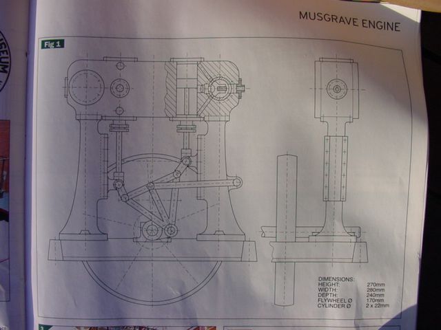
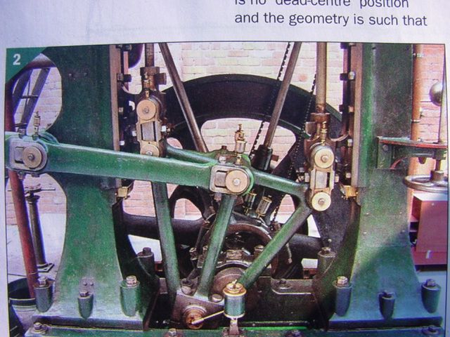
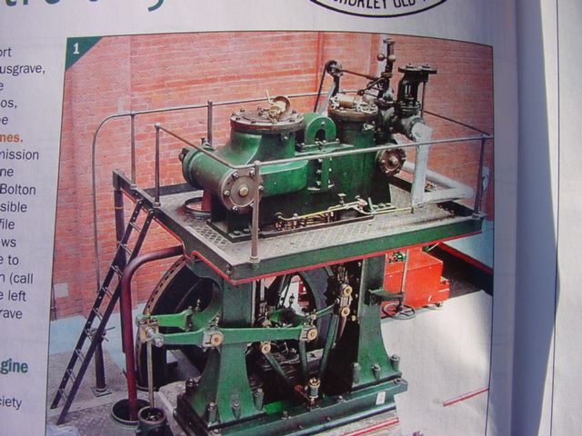
                                            Here is something interesting. I got an ME mag from the library today and found this article.


                                            We like to call this the Ross Yoke . . . MMMMM.
                                            The article, if you want to check it out, is im ME Vol.202 No 4350 24th april . 7th May 2009.
                                            Mark
                                            P.S. for some reason the site won’t accept scanned pics so I had to photograph the pages.

                                            Edited By Mark Smith 3 on 31/01/2010 07:04:30

                                            #48077
                                            Ian S C
                                            Participant
                                              @iansc

                                              Yes theres nothing new,even this one wasn’t new, in 1838 some one by name of Galloway (think thats right) built one with the cylinders at the bottom, crank at the top. The one in your photos, according to Wikipedia is in the Bolton Steam Museum, and is called a non dead center engine. The theory by some on the “net” is that the Ross patent is for the ballance system ie the ballance shaft.Not long in form the workshop, I’ll proberbly have a stiff arm in the morning, I’v been lapping cylinders, I’ll finnish them tomorrow, I want them like mirrors in the bore.Tried the alternative system of stabalizing the bellcrank, it looks worth while, once I get the engine running I may change from the side rod to a central pin. I found a LTD motor using that system. Ian S C

                                              #48104
                                              Mark Smith 3
                                              Participant
                                                @marksmith3
                                                My Ross yoke Rider is nearly ready to start, just have to get the cylinders tigged and braze the transfer tubes. The mechanism is suprisingly quiet. You could use half of this mechanism to make a power hacksaw. The advantage being that the rods run in an almost perfect staight line and the crank throw is small compared to the stroke, or has that already been done?
                                                Mark
                                                #48109
                                                Ian S C
                                                Participant
                                                  @iansc

                                                  You’r a bit ahead of me,I’m slowly plodding on, I’ll start making the pistons today.I think I ‘ll have a interesting time with the cylinder head I’v designed, it will require a 4mm hole about 90mm long, done it before,so no doubt I can do it again.That will be the transfer port,there may be two of them. Ian S C

                                                  #48345
                                                  Mark Smith 3
                                                  Participant
                                                    @marksmith3
                                                    Clive 1958, Further to your suggestion re. oil or liquid pistons, have a look at this link someone else is thinking along the same lines. http://www.halfbakery.com/idea/stirling_2fturbine
                                                    My rider engine is at the testing stage but so far refuses to run, seems to have good compression and bounce etc. but no go. My last engine gave me a lot of trouble until I ironed out the wrinkles and now it is one of my easiest starters. Just have to persevere. . .
                                                    Mark
                                                    #48364
                                                    Ian S C
                                                    Participant
                                                      @iansc

                                                      Mark I was just looking at the above site,I don’t know why he wants to use a Ross yoke and a flywheel when he could use a linear alternator, no crank needed, but the system is best used as a pump, the fluid being pumped is also the displacer, and piston.My Rider is getting its cylinders made, fitting the water jackets, next to make is the cylinder head. You might be able to tell me, is it practical to weld tha thin tube that I gave you? If so how should I prepare the piece to go on top to give it a flat top like your piece of vacuum cleaner tube? Ian S C

                                                    Viewing 25 posts - 251 through 275 (of 457 total)
                                                    • Please log in to reply to this topic. Registering is free and easy using the links on the menu at the top of this page.

                                                    Advert

                                                    Latest Replies

                                                    Home Forums Beginners questions Topics

                                                    Viewing 25 topics - 1 through 25 (of 25 total)
                                                    Viewing 25 topics - 1 through 25 (of 25 total)

                                                    View full reply list.

                                                    Advert

                                                    Newsletter Sign-up