Im building small steam engine on my lathe and I have come to a point where i need manometer on my boiler.
Im looking for ideas how to build it.
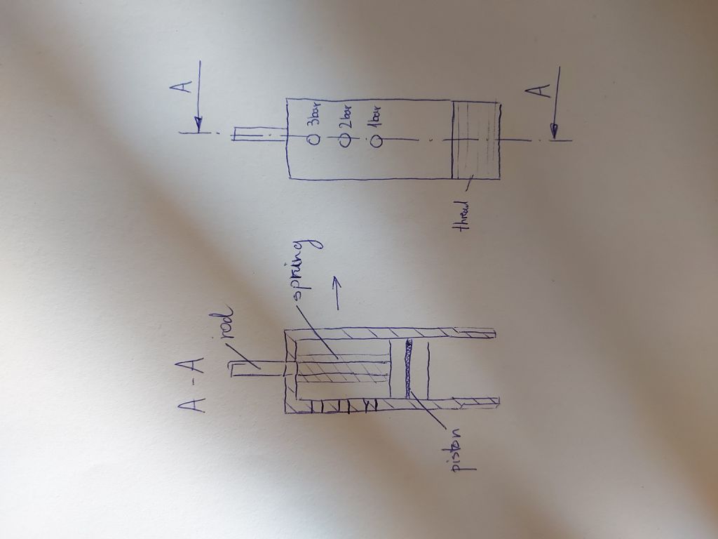
My own first idea was making small cilinder with a piston that has piston rod spring loaded. Then i would make vertical dial on cilinder, calculate spring elastic energy and calculate distance for each bar then i drill small hole on proper calculated distance for each bar. (max3). Sorry if my english is bad, Im not from UK,
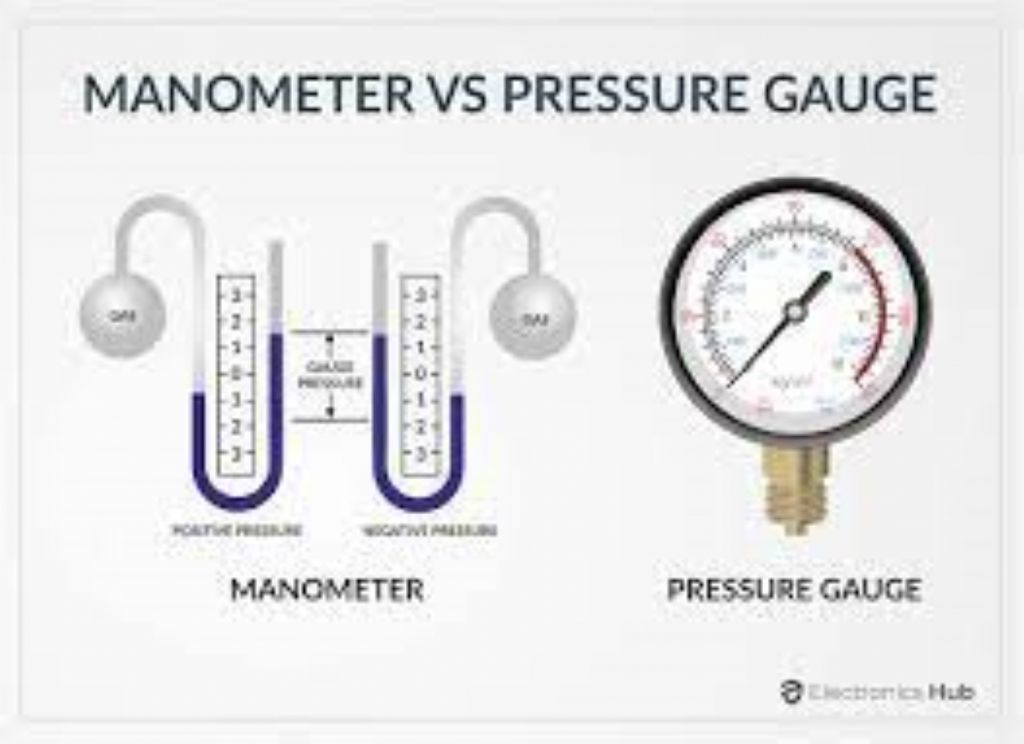
Hello Martin. Do you mean a manometer or a pressure gauge ?
A manometer is a U shaped tube, used for measuring small pressure. Steam boilers usually have a pressure gauge. Small pressure gauges are available from model supply stores. Do a google search for pressure gauge construction if you want to build your own. (not an easy project if you only have basic tooling)
A manometer would not be any use in the situation of measuring steam pressures as it consists of a tube that is open to atmosphere at one end, you definitely need a pressure gauge, please be aware of the correct way to connect the gauge to your boiler system. Dave W
Yep, as above (for most measurements). One Bar would equate to ~760mm of mercury, or approx 10m of water! Most manometers for low pressure differences are filled with oil of less than unity density (specific gravity) unless of a temporary nature.🙂
Paul, sorry but I am going for the pedant role here
Tubes for manometers are not always U shaped. I went to a museum at Farnborough where they had test equipment used in the investigations into flight and the design of aerofoils. Their manometers were V shaped with one leg vertical and the other sloping at about 30° from the horizontal in order to make the difference in levels more readable.
Additionally at work we hade low pressure differential transmitters by Rosemount that were referred to as manometers even though there was no tube of any shape containing liquid.
I guess you want a pressure gauge rather than a manometer. A manometer is a particular form of pressure gauge, and the type isn't really suitable for a steam engine. (The range of pressure they can measure is small, they're physically big, and don't like vibration.)
Your piston and spring would work. As would weights holding a V shaped piston down like a safety-valve. The problem with both is stopping the piston from leaking.
Mr Bourdon came up with a good answer in 1849 and this type of gauge is very common today. They're cheap, reliable and cover most ranges needed. Bourdon bent a flattened tube into a curve, which is also a spring. No leaks because the tube is sealed at the far end. When the springy tube is pressured, it straightens out in proportion to the pressure. The resulting small movement is used to drive a needle through an amplifying step-up lever and gears.
Rarely home-made these days because commercial gauges are so cheap and come calibrated and ready to go.
Though I've never seen a published design people occasionally make their own: I gather the tube is the main problem.
Usually Brass, it has to be springy enough to provide the wanted pressure range – not too stiff, or too light. Springiness depends on the type of Brass, how hard it is, the diameter of the tube, and the thickness of the walls. The radius of the tube matters too, and it can be coiled. The tube is flattened so that it opens out in one direction: round tubes move sideways as well as out.
Gauge manufacturers have all the information needed, but I don't think it's been made public. Therefore, a home-builder has to experiment. Great fun, but far quicker to buy one rather than build it.
There are other possibilities: if electronics are allowed, a strain-gauge could substitute for the needle, gear and lever assembly, and the range covered is decided by an amplifier. Electronic pressure gauges are available but ones that work at high temperature and pressure are expensive. Worth it for logging data or informing an engine management unit, but a pricey fuss if all that's wanted is a visual indication of boiler pressure.
Please report back. Be really good is someone built a Bourdon Gauge and explained how they did it.
I do apologize for misunderstanding, in my country we call pressure gauge manometer. Im attaching my sketch of the idea; also the distance between holes must be correct otherwise becouse of the piston the pressure in boiler will drop, so i will have to pick the right spring.
Your idea will work to an extent, but friction in the seal will cause a lot of hysteresis, so when pressure is rising it will read low, and when it's falling it will read high. Because of stick slip you might find it changes in jerks. If you could find a metal bellows it would be better, but a difficult search
In Uk, and in many nbother countries, a manometer is, as said, often a U tube filled with a fluid.
The pressure is measured as the difference in height between the two columns The largest that I ever used was to mesure boost pressures of the orfer of 1.7 m of Mercury.
For lesser pressures our manometers were of a different, proprietary for, but still using Mrcury as the fluid.
For small pressures, water or light oil can be used.
To measure boiler pressures, what you need is a Bourdon tube type pressure gauge, as previously illustrated.
They should be available from model engineering suppliers, in Uk, such as Reeves.
A similar but more "sophisticated" oil pressure button was used on early Austin 7 cars however the engine pressure rarely rose above 20psi and normal running was probably 5psi.
When one can buy a well made and fairly accurate bourdon type pressure gauge for around 8 US dollars (or your local equivalent) why are we discussing ways for the OP make an inferior alternate? See link to e b ay example candidate below.
When one can buy a well made and fairly accurate bourdon type pressure gauge for around 8 US dollars (or your local equivalent) why are we discussing ways for the OP make an inferior alternate? […]
.
As a disinterested and uninterested observer … I would guess it’s something to do with Model Engineering vs playing with trains.
Dunno nuffing about the rules in Slovenia, but in the UK one of the fundamental requirements under the Pressure System Regulations is to have a calibrated and reliable means of indicating the pressure in a pressure vessel at all times. I don't believe (though I'm ready to be corrected) that this requirement is relaxed for a vessel below the relevant bar-volume exemption for low pressure/low volume systems. A simple risk assessment indicates that a pressure gauge is necessary.
If I was the insurer I'd want to see such a safety critical feature of the system present and demonstrably correct.
I'm a bit puzzled by the small holes in the side of the cylinder in the sketch. They make the device look more like a simple pressure-regulator.
I can understand a piston-type gauge working by graduations on the rod protruding from the top though.
However, it is normal practice to give the gauge or sensor some protection from the hot steam by a U-bend in the tube from boiler to gauge. Often called a "syphon" though it is not really a syphon, it becomes partly filled with water so the gauge feels only air at the boiler pressure.
| Posted by Nigel Graham 2 on 10/08/2023 21:28:17:
I'm a bit puzzled by the small holes in the side of the cylinder in the sketch. They make the device look more like a simple pressure-regulator.
I can understand a piston-type gauge working by graduations on the rod protruding from the top though.
However, it is normal practice to give the gauge or sensor some protection from the hot steam by a U-bend in the tube from boiler to gauge. Often called a "syphon" though it is not really a syphon, it becomes partly filled with water so the gauge feels only air at the boiler pressure.
———————————————————————————————————————-
Maybe i should remove O-Ring on piston and put inside cilinder Φ6mm transparent pneumatic tube and this would seal piston from leaking and the piston position on holes would still be clearly seen becouse of transparent pneumatic tube.
You could make a gauge like that, with a scale along the side of the tube, but you'd certainly need protect the tube from the heat of the boiler. Or use boiler gauge-glass tube.
I can make U-tube bend from copper like you said, maybe I should check tables for different types of plasic and their temperature points to see at what temperature range it softens. Also is this gauge-glass tube purchasable, i have never seen it, maybe i could cut glass test tube.
Bear in mind you need know the boiler temperature at working-pressure, and it will be above 100ºC.
Don't use a test-tube. They are very thin-walled and very unlikely to be strong enough to use as you suggest. Gauge-glass tube walls are about 2 thick even in model sizes, and of much smaller diameter than a test-tube..
Author
Posts
Viewing 22 posts - 1 through 22 (of 22 total)
Please log in to reply to this topic. Registering is free and easy using the links on the menu at the top of this page.