Hoglet Build

Advert

Hoglet Build

Viewing 25 posts - 26 through 50 (of 134 total)
  • Author
    Posts
  • #228609
    Michael Gilligan
    Participant
      @michaelgilligan61133

      My memory failed me blush

      … according to Wikipedia, it dates back much earlier.

      MichaelG.

      Advert
      #228618
      JasonB
      Moderator
        @jasonb

        College engineering or M-machine will have HE15 or 2014 as its now known, start saving up and don't make a scrapper! This is the usual choice for small IC engine con rods.

        M-Mac hine have a better range of flat section but do the maths as its sometimes cheaper to buy round and mill it flat.


        Edited By JasonB on 06/03/2016 16:59:57

        #228641
        Nick_G
        Participant
          @nick_g

          .

          Cheers guys. smiley

          Nick

          #228998
          Nick_G
          Participant
            @nick_g

            .

            Took a trip today to Mac Models in Macclesfield to buy some steel, aluminium and cast iron.

            While I was out that way I took a blast on my motorbike up the 'Cat & Fiddle' road for an adrenaline rush. devilsmiley

            Anyway. Those materials should keep me busy for a while on this Hoglet thing.

            Nick

            #229001
            JasonB
            Moderator
              @jasonb

              Looks like you are going to do the kick start as well, I just went with the basic engine, so I will allow you a day or two extra to get it donewink 2

              #229005
              Nick_G
              Participant
                @nick_g
                Posted by JasonB on 08/03/2016 13:39:18:

                so I will allow you a day or two extra to get it donewink 2

                .

                Errrrrrrrrrr. ……………………… What date year did you start your Hoglet Jason. And at what stage is it at now.? devil

                Nick wink

                #229085
                Nick_G
                Participant
                  @nick_g

                  .

                  Thought I better do something useful with that metal. So had a stab at one of the cylinders.

                  The drawing calls for the cylinder to be made in one piece from cast iron. Many others though have opted to make them from aluminium and then sleeve with a cast iron liner. – I went for an all cast iron one as per the drawing.

                  Macc models did not have the close size for the cylinder dia. So I went a size larger and will part off the excess length I bought to make the cylinder head. (which is a larger dia) This meant I had to spend a bit more time carving down to the cylinder dia.

                  Then cut in the cooling fins.

                  Then ready to part off. – I think CI is really nice to machine if it's good quality stuff. Pity it makes such a damned mess though.

                  Fliiped it round into the collet chuck and a boring session we did go.! At this stage I also added the 5 degree taper to some of the fins. – The bore is quite a nice finish with it being nice CI. But left 1/2 though for a tad of honing.

                  Hey presto. smiley

                  There is a wide groove to be made yet below the bottom fin that makes a step in the lower section to form a flange. I will do this later when I have both cylinders done and made a mandrel to hold them.

                  Now I have to make another one that 'looks' wink exactly the same.!


                  Nick


                  Edited By Nick_G on 08/03/2016 23:36:38

                  #229099
                  JasonB
                  Moderator
                    @jasonb

                    Looks good Nick, did you go full depth with the round nosed tool to do the grooves or just use that to finish the bottom?

                    Watch that the angled fins don't throw your holes for the four studs off, I had a couple drift with straight fins, may be worth leaving the second one flat until the holes are drilled and then add the taper.

                    J

                    PS Will take a picture of the state of play on mine later

                    #229105
                    Michael Gilligan
                    Participant
                      @michaelgilligan61133

                      Nice work, Nick … it's looking rather fine already.

                      Also good to see the quality of Macc's Cast Iron.

                      MichaelG.

                      #229127
                      Neil Wyatt
                      Moderator
                        @neilwyatt

                        Where did the square flange on the bottom of the cylinder come from, and how is it attached?

                        #229131
                        JasonB
                        Moderator
                          @jasonb

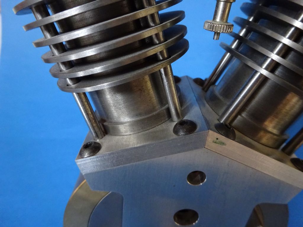
                          Thats the bit of aluminium Nick posted earlier not a flange on the piston.

                          The aluminium plate is drilled & tapped for four long studs, these pass through the cylinder and head and the whole lot is held on with four nuts which pull the cylinder down against the flange that Nick mentions he still has to machine.

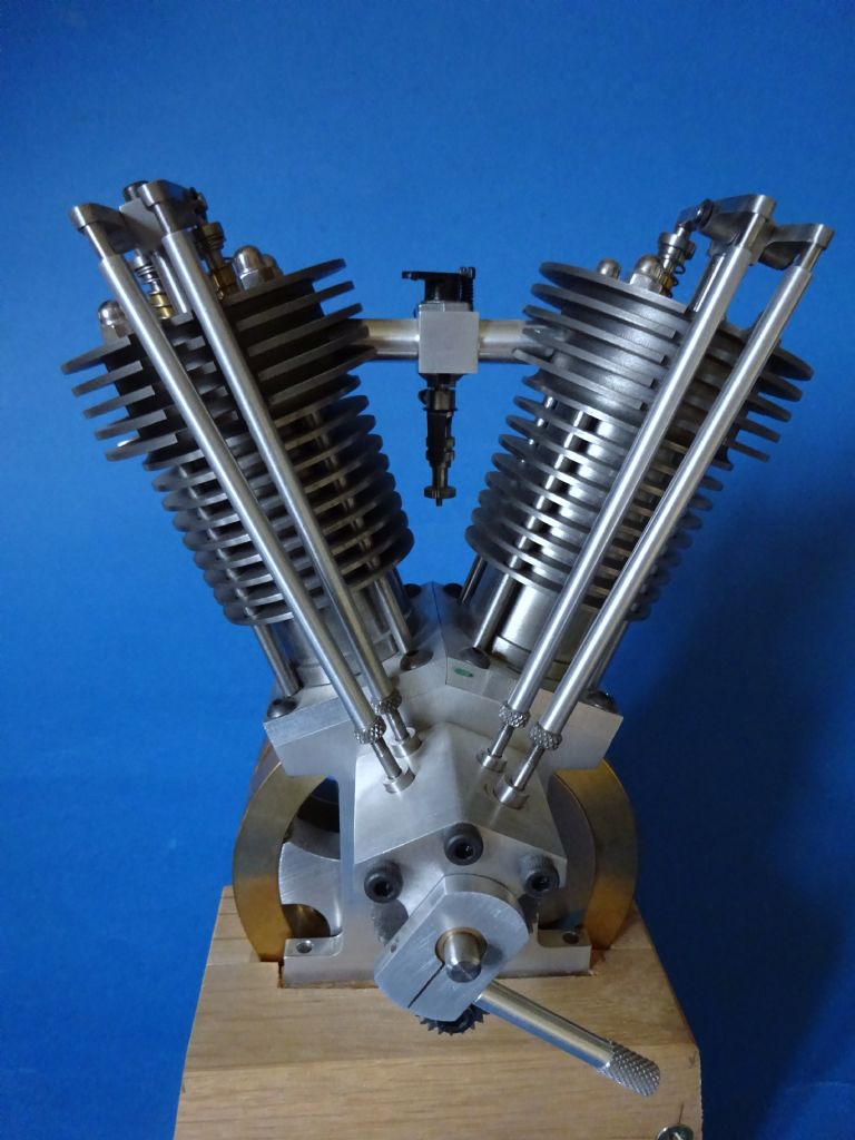
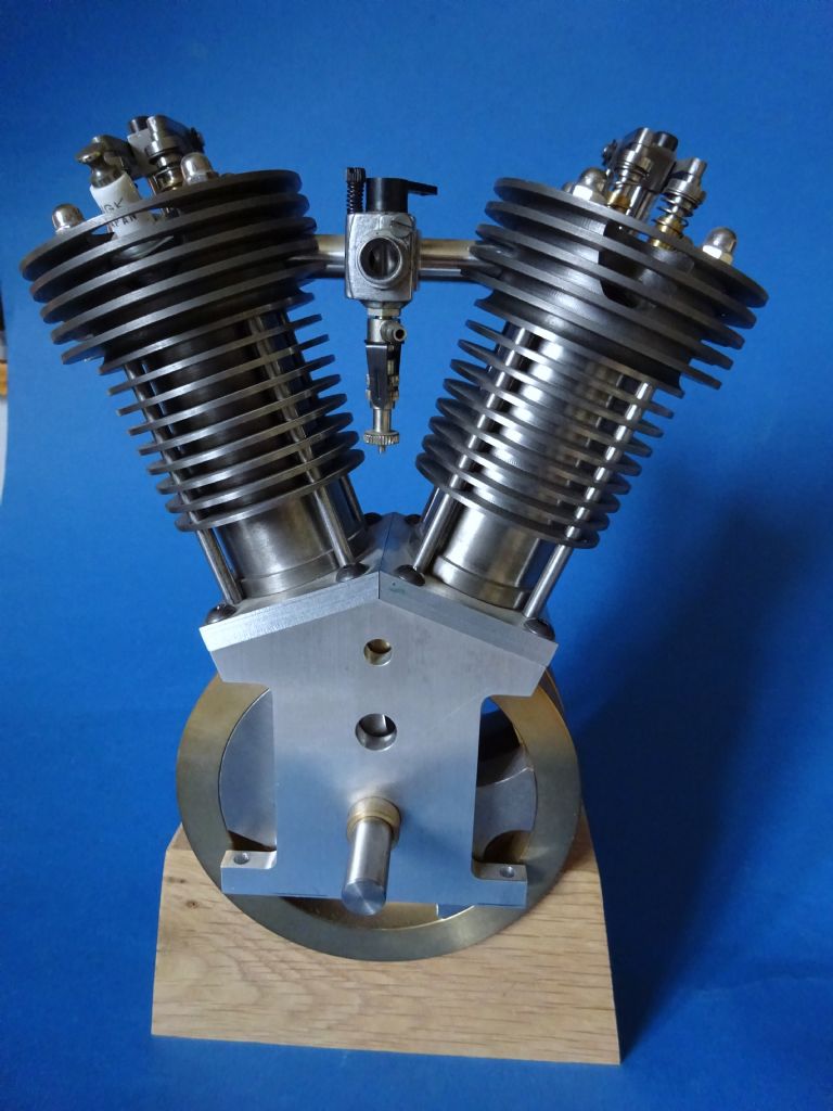
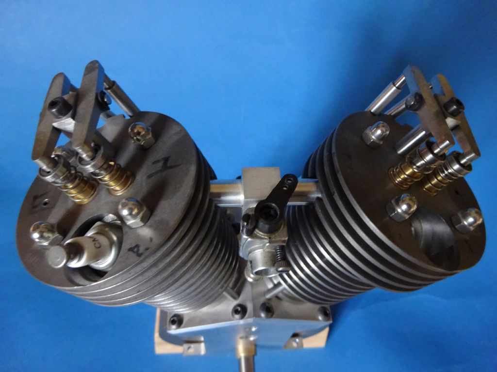
                          dsc00939.jpg

                          And for Nick this is the current position with mine, just teh exhusts to do and drill for magnets and hall sensor for the ignition.

                          dsc00936.jpg

                          dsc00937.jpg

                          dsc00938.jpg


                          Edited By JasonB on 09/03/2016 09:52:47

                          #229136
                          Danny M2Z
                          Participant
                            @dannym2z
                            Posted by Neil Wyatt on 09/03/2016 09:28:50:

                            Where did the square flange on the bottom of the cylinder come from, and how is it attached?

                            I was wondering the same thing Neil. Presumably it's brazed on and final cylinder honing/lapping is yet to come.

                            * Danny M *

                            #229137
                            Nick_G
                            Participant
                              @nick_g

                              .

                              Like this.

                              .

                              Jason, I did go full depth with the form tool for the fins.

                              Nick

                              #229139
                              JasonB
                              Moderator
                                @jasonb

                                I have edited my post with some phoptos which also show the construction for Neil.

                                While I'm on the point was raised about it being an open crank, the Hoglet is actually one of a number of open crank engines that Randall Cox designed the others being a twin, straight 4 and this rather impressive straight 6 which is known as the "Open Six" The lareg centrifugal fan on the front blows air over the cylinders. If anyone fancies a go then plans and build article are in te first two issues of Model Engine Builder mag.

                                Nick I like that jam jar fuel tank, it would look good on your hog if you can find something small and like jam

                                Edited By JasonB on 09/03/2016 10:03:13

                                #229141
                                Nick_G
                                Participant
                                  @nick_g
                                  Posted by JasonB on 09/03/2016 10:02:12:

                                  Nick I like that jam jar fuel tank, it would look good on your hog if you can find something small and like jam

                                  .

                                  An air brush paint jar.? ………… Almost ready made for the job with a pick-up tube.

                                  Nick

                                  #229232
                                  gary
                                  Participant
                                    @gary44937

                                    good work nick, very interesting where did you get the drawings?

                                    #229235
                                    JasonB
                                    Moderator
                                      @jasonb

                                      Drawings and build article were in Model Engine Builder issues 10 & 11. You can now by them digitally, go to Subscribe along the top, then subscribe online and it lists all te back issues

                                      #229243
                                      daveb
                                      Participant
                                        @daveb17630

                                        JasonB, that's a lovely job!

                                        #229260
                                        JasonB
                                        Moderator
                                          @jasonb

                                          It should be even better when I get round to finishing itblush

                                          #229558
                                          Nick_G
                                          Participant
                                            @nick_g

                                            .

                                            Moving on. smiley I made the second cylinder OK.

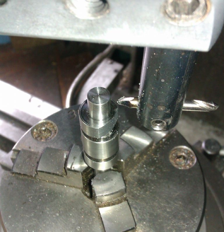
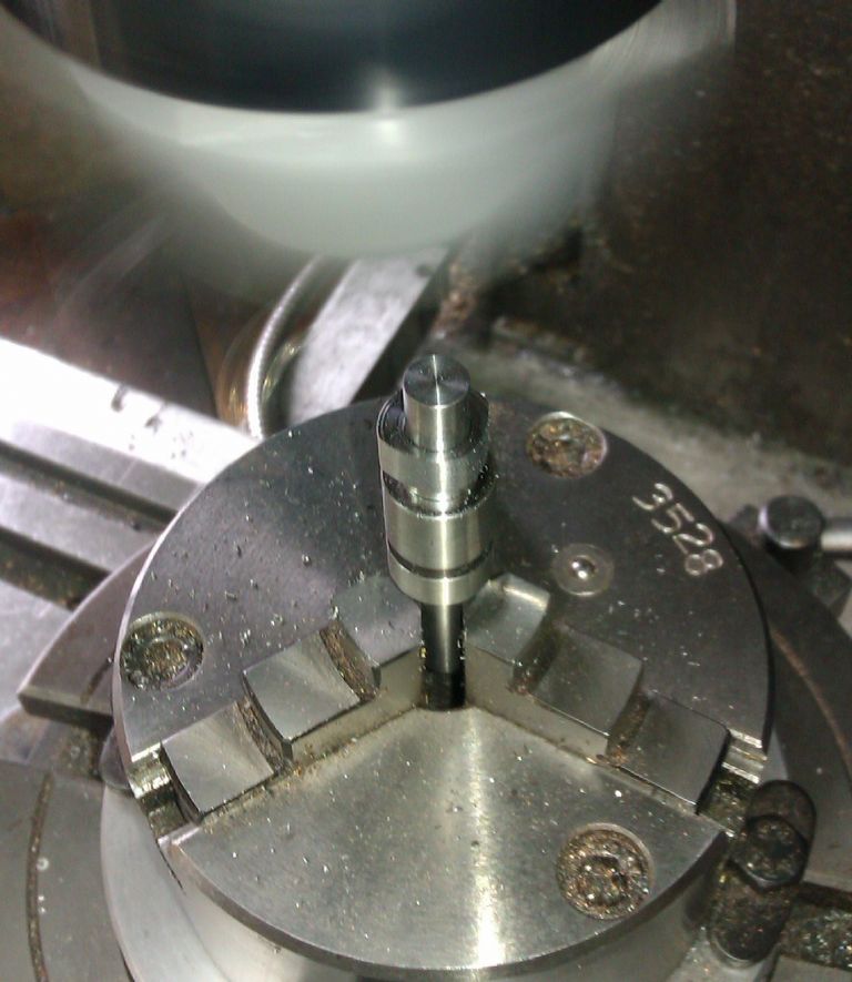
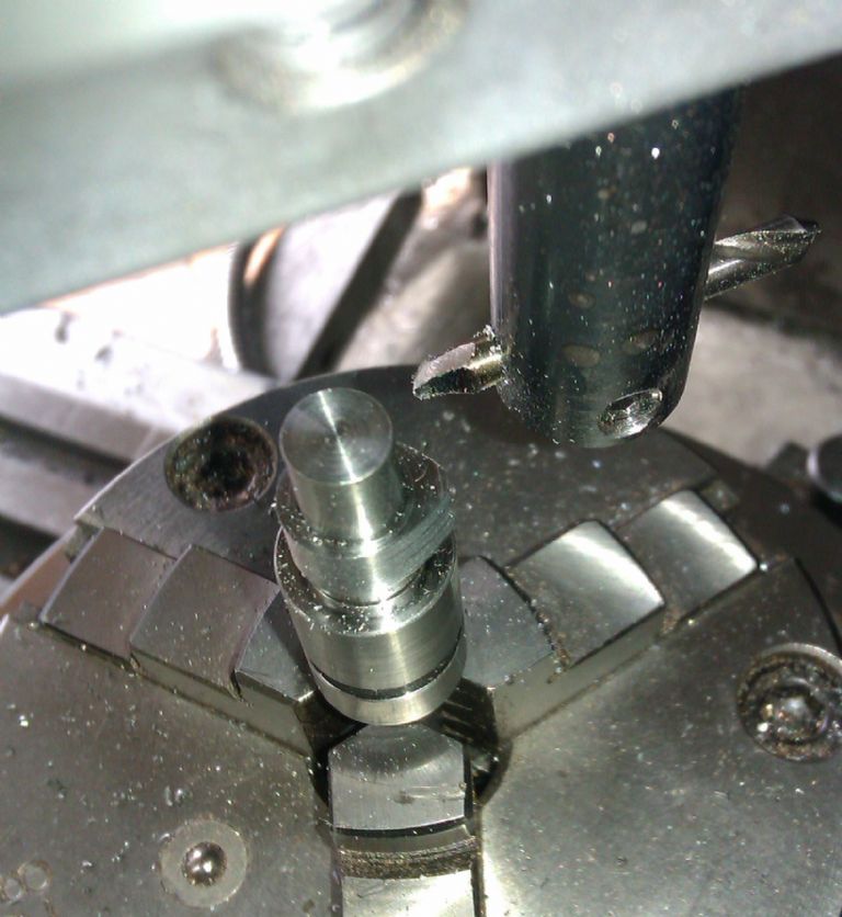
                                            Over to the mill and used the DRO to drill the holes through the cooling fins.

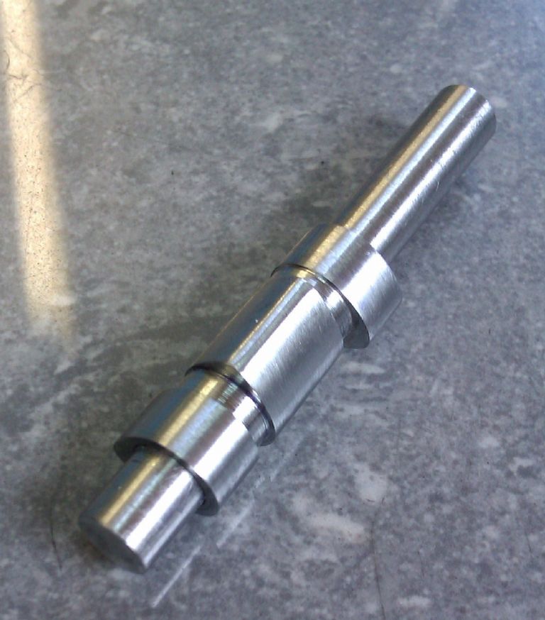
                                            Made the 8 studs. Threaded them at just one end for now and will get the final length when I have the heads done.

                                            So far it seems to be going to plan. smiley

                                            The drawing does not make any mention of a cylinder head gaskets. ………. I am presuming it will need them.? Suggestions of material and thickness please guys.

                                            Nick

                                            #229574
                                            JasonB
                                            Moderator
                                              @jasonb

                                              I tend to use a liquid gasket from the likes of Halfords, its basically a silicon type in a toothpaste size tube. You just need a smear of it so don't need to allow for any extra thickness

                                              #229592
                                              Nick_G
                                              Participant
                                                @nick_g

                                                .

                                                Cheers Jason,

                                                The camshaft is an item that I may struggle with as I have never done such a thing. – Think I have the kit to do one and watched a few youtube videos …………. But they are all a bit Greek and voodoo dark art to me. blush

                                                Nick

                                                #229606
                                                JasonB
                                                Moderator
                                                  @jasonb

                                                  You need a Rotary table and boring head with a simple tool holder, set up and cut one face of the cam.

                                                  imag1507.jpg

                                                  Then keep making plunge cuts as teh table is turned say 2deg at a time

                                                  imag1508.jpg

                                                  Until you are left with something looking like a cam, just file the tip radius

                                                  imag1509.jpg

                                                  Then when you have done it for the other cams it should look like this

                                                  imag1510.jpg

                                                  Simples!

                                                  #229982
                                                  Nick_G
                                                  Participant
                                                    @nick_g

                                                    .

                                                    Cylinder heads next I think.

                                                    The drawings give details of a jig to hold the head while the machining of inlet and exhaust ports, spark plug holes and cooling fins take place. The valve guide holes and head securing holes have to be made into the cast iron blank first to enable it to be fixed. – These are then a ref point for everything else.

                                                    So this eve I made the jig from a length of 2"x2" square bar as suggested.

                                                    I am wondering …………. And thus asking the members here if they think I should machine the ports and spark plug hole first then the cooling fins. Or fins first then the holes.?

                                                    Here is a section of the drawing detailing the head.

                                                    Also not sure of the best way to secure the valve guides when the time comes.?

                                                    I gather that one of the main issues and problem areas with a small 'home made' IC 4 strokes is getting the valves to seal properly with the head.

                                                    Thanks, Nick

                                                    #229986
                                                    Emgee
                                                    Participant
                                                      @emgee

                                                      Nick, if you don't machine the fins before parting off the head I suggest you at least drill and ream for the guides as the 1st op on the parted off piece so you can fix the head to a jig by screwing thro the guide positions.

                                                      You may be able to use 1 grub screw at the centre of both guides, the threaded hole would need to extend to each guide and provide evidence of a thread on each.

                                                      Emgee

                                                      Edited By Emgee on 14/03/2016 22:50:44

                                                    Viewing 25 posts - 26 through 50 (of 134 total)
                                                    • Please log in to reply to this topic. Registering is free and easy using the links on the menu at the top of this page.

                                                    Advert

                                                    Latest Replies

                                                    Viewing 25 topics - 1 through 25 (of 25 total)
                                                    Viewing 25 topics - 1 through 25 (of 25 total)

                                                    View full reply list.

                                                    Advert

                                                    Newsletter Sign-up