Help with square thread

Advert

Help with square thread

Home Forums Beginners questions Help with square thread

Viewing 25 posts - 1 through 25 (of 35 total)
  • Author
    Posts
  • #605542
    Nicholas Hill
    Participant
      @nicholashill23289

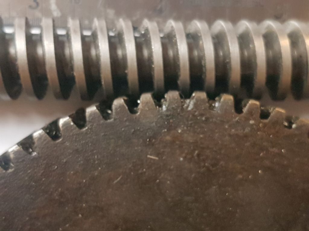
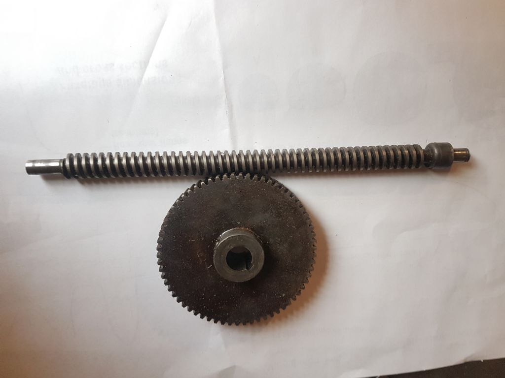
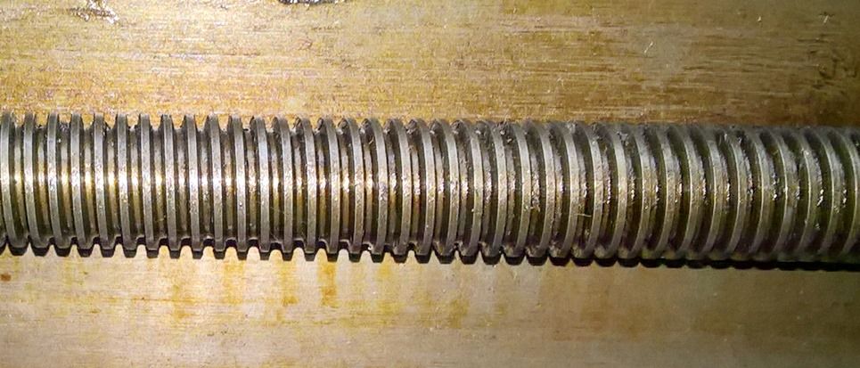
      FEED_SCREW_DETAILHello, I am getting very confused by square threads.

      I need to make a feed screw for my Milling Machine, and can't identify what type it is.

      It seems too deep for an Acme thread, and too sloped for a square thread.

      The dimensions I have are;

      Outer diameter = 5/8

      Inner Diameter = 3/8

      TPI = 5.

      The best I can measure the thread, it is approx 0.08in wide with a gap between threads of 0.12in to make up to the 0.2in for 5 TPI.

      According to wikipedia, an Acme thread of 5/8 should have 8TPI.

      So is it a wide Acme thread? Or a square cut one?

      If an Acme thread, do I need to grind a cutter to the correct 29 deg angle? I have a Myford and a grinding wheel, so can this be done using the top slide? So the angles are precise?

      Or any other clues would be most helpful. I last cut a thread about 20 years ago in a college workshop…

      Many thanks in advance, and sorry if the description is a bit garbled. Threads still confuse me. Every bolt I come to is always a trial and error..is it a Whitworth, a BA, a metric, a AF….So Acmes, Square threads, Trapeziodal threads….,

      FEED_SCREW

      Advert
      #11263
      Nicholas Hill
      Participant
        @nicholashill23289
        #605547
        old mart
        Participant
          @oldmart

          Square threads are sometimes made with slightly sloping flanks, that may be why you are having trouble.. If you have any slips, you might find the taper by checking the unworn part of the thread.

          #605548
          David George 1
          Participant
            @davidgeorge1

            Fairly easy to make a cutter from HSS. Just copy the shape of the thread form from the original on to a piece of tool steel and make sure there is cutting clearance on end and both sides but leave the top flat. Then just turn the blank to size and plunge the cutter in till correct depth 8 TPI.

            David

            #605551
            not done it yet
            Participant
              @notdoneityet

              Is it not a worm? Driving a worm wheel?

              #605552
              Anonymous

                Looking at the picture the thread is definitely Acme/trapezoidal, not square. Forget Wikipedia, Acme style threads can be whatever the manufacturer decides, although there are standards for the shape of the thread form.

                Looking at the picture can we assume that the screw mates with a gear? If so then the flank angle of the thread should match the pressure angle of the gear. Furthermore the depth of the thread will be determined by the addendum and dedendum of the mating gear.

                Andrew

                #605557
                Oldiron
                Participant
                  @oldiron
                  Posted by David George 1 on 12/07/2022 21:35:17:

                  Fairly easy to make a cutter from HSS. Just copy the shape of the thread form from the original on to a piece of tool steel and make sure there is cutting clearance on end and both sides but leave the top flat. Then just turn the blank to size and plunge the cutter in till correct depth 8 TPI.

                  David

                  OP quotes 5 TPI

                  regards

                  #605570
                  Nicholas Hill
                  Participant
                    @nicholashill23289

                    20220713_003649.jpgThanks for the replies.

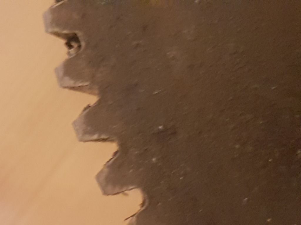
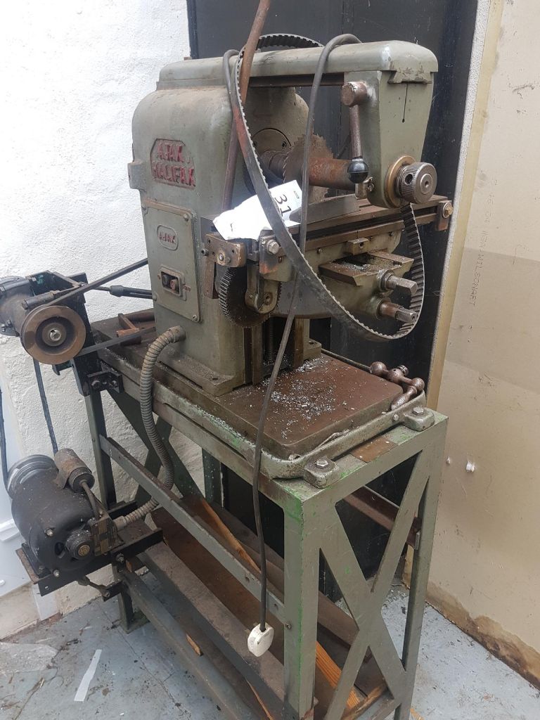
                    To add more details, I have added a photo of the whole mill, and a close up of the large gear wheel tooth.

                    The part I am replacing is the feed screw for the table. The Mill was dropped in transit, and the handle broke off. I've had it for a few years, and have been putting off repairing it. But needed a circular saw this week, and so it prompted me to look again.

                    So, the consensus seems to be it is an Acme, but use the existing thread form as a guide. How accurate does the grind have to be for the tool? If it is a Acme thread, then should it be 29 deg? Would that be two angles of 14.5deg? I can't imagine my freehand grinding would be accurate enough, hence the thoughts of using the lathe.

                    I can set the tool post to the correct angle, and with the grinding wheel in the chuck, get pretty close. But will this damage the lathe?

                    Do I need to think of anything special regarding the cutting tool? With the depth of the cut, and the the narrowness of the blade, I fear broken cutters all over the place. Parting blades are notorious for breaking, well at least with me! What speed should I run at? Is it better to go fast or slow? Does it need coolant?

                    Anyway, many thanks for the guidance.

                    Nickajax_all.jpg


                    Edited By Nicholas Hill on 13/07/2022 01:29:22

                    #605575
                    DC31k
                    Participant
                      @dc31k
                      Posted by Nicholas Hill on 13/07/2022 01:28:21:

                      Would that be two angles of 14.5deg? I can't imagine my freehand grinding would be accurate enough, hence the thoughts of using the lathe.

                      Make a gauge. Draw out the 29.5 degree angle on, for example, an A3 size piece of paper with lengths derived from trigonometry. Let us assume you can measure to a resolution of 1mm. Calculate how different the angle would be if you are 1mm wrong at that size (opposite side at A3 size is 237.6mm, so calculate for 237mm and 238mm). Assess whether that error is significant.

                      #605577
                      David George 1
                      Participant
                        @davidgeorge1

                        This video on you tube is me cutting a 0.100 pitch square thread in silver steel. The tool is tool steel hand ground on a solid piece of square not a part of blade.

                        David

                        Edited By David George 1 on 13/07/2022 06:54:49

                        #605579
                        JasonB
                        Moderator
                          @jasonb

                          From the approx sizes you give in the first post 0.08" crest, 0.12" gap and 0.125" deep you have an angle of just over 18degreed (9.1deg each side) which could suggest it mates with a gear cut with a 20pa cutter.

                          Are the gear teeth cut straight across or at an angle making it a skew gear to match the helix angle of the screw. If it is cut at an angle don't take any measurements off the side of the gear wheel as they need to be taken at right angles to the teeth which may increase the angle if that is what you are taking your measurements from.

                          Lastly if the handle broke off is the rest of the screw still OK? if so think about grafting on a replacement rather than cutting again.

                          #605596
                          Nigel McBurney 1
                          Participant
                            @nigelmcburney1

                            Long time ago company practice was to grind the thread cutting tools by hand on a grinder with a well dressed wheel,though we had the avantage of an optical projector to finally check the tool angle,though its easy to file up a guage from 1/16 steel pate, the tool was a 3/8 square HSS toolbit used on a Boxford, Apart from getting the angle correct,the clearance on the sides of the tool must be ground to clear the helix of the thread,when cutting a RH Acme the side of the tool on the chuck side requires more clearance as the helix on small dia coarse thread is relatively large, I nowadays have learnt that its better to use a round HSS toolbit clamped in a holder this allows the toolbit to be rotated so that the cutting form can be aligned to the thread helix by setting the old feedscrew up in the chuck to esnure there is clearance on both sides of the tool,then the top cutting edge can be ground to be horizontal with the lathe axis. Always cut with lubricant at a slow speed,on long threads use a traveling steady to stop the workpiece from deflecting away from the tool,otherwise you will find the thread will be tight and oversize in the centre.

                            #605600
                            MadMike
                            Participant
                              @madmike

                              I would seriously consider remaking the cast bloc which supports the end of the screw so the more of the screw protrudes, then weld a stub/extension to the spindle, carefully machine the welded area to the original size, and fit the handle etc to the extension on the shaft. It would take away all of the anxiety that appears to present with identifying the correct thread form and the making of a suitable cutting tool etc. If threads are a problem, real or perceived, Nicholas simply look for an alternative……it's what engineers do.

                              #605609
                              JasonB
                              Moderator
                                @jasonb

                                If you do end up making a new screw then you should be looking at the fit with the nut as the most important not the gear/worm wheel as it seems from a bit of googling that is only a quick action feed which you are unlikely to use very often and converts the screw into a rack with the wheel being the pinion.

                                #605612
                                Hopper
                                Participant
                                  @hopper
                                  Posted by Nicholas Hill on 13/07/2022 01:28:21:

                                  Do I need to think of anything special regarding the cutting tool? With the depth of the cut, and the the narrowness of the blade, I fear broken cutters all over the place. Parting blades are notorious for breaking, well at least with me! What speed should I run at? Is it better to go fast or slow? Does it need coolant?

                                  Not wanting to sound obtuse, but it does not sound like you have the experience needed to cut a difficult and critical thread like this one. It is not a beginner project. You would be far, far better off to remachine the end of the existing screw so you can re-attach the handle.

                                  This is usually simply done by mounting the screw in the lathe and machining the broken end flat and with a hole drilled and reamed in it so you can then turn up a replacement end part with a spigot sticking out that fits in that hole. You then fasten the two together by whatever methods suits, possibly Loctite, or silver soldering, or even careful TIG welding, or drilling and cross-pinning. This is much more achievable than cutting an obscure Acme-like 5TPI thread on a long thin screw to precision tolerances if you are not an advanced level lathist.

                                  Edited By Hopper on 13/07/2022 11:59:47

                                  #605620
                                  vic newey
                                  Participant
                                    @vicnewey60017

                                    Just for clarity here is the square threaded lead screw of my 1937 Holbrook B8 which has square threads on the feed screws as wellsquare.jpg

                                    #605627
                                    HOWARDT
                                    Participant
                                      @howardt

                                      Looks like a helical gear and worm, not easy to get the worm cut correctly to mesh fully. Interesting information here that I often used to use KHK Gears

                                      #605631
                                      JasonB
                                      Moderator
                                        @jasonb

                                        That is why I suggested forgetting about the pinion and paying more attention to the fit of screw and nut

                                        #605632
                                        Nigel Graham 2
                                        Participant
                                          @nigelgraham2

                                          No – don't try cutting a new screw with that great long, fancy-thread, high-lead!

                                          Go with the extension-piece approach. It is transmitting only your hand-power, and there seems nothing wrong with the rest of the mechanism.

                                          It's more than the technical problems of work and tool geometry, shown above.

                                          Do you have a heavy-duty lathe actually designed to cope with such coarse threads, i.e. one having a 2 or at worst, 4 TPI lead-screw and change-wheels to match? Or the equipment for thread-milling?

                                          Cutting a heavy thread coarser than the lead-screw, especially on a fairly light machine, is bad practice. It puts very unfair strains on the machine; even with the recommended "only if you really have to" practice of disconnecting the normal power drive and operating the lathe manually, "backwards" , from a handle on the lead-screw.

                                          .

                                          Use the method Hopper describes, though personally I'd not try welding or soldering, for such tasks. It can risk distorting the screw itself. If there is enough shaft projecting from the bearing you can alternatively use a tightly-fitting external sleeve, with pins. This is arguably stronger as you are not reducing the screw's cross-sectional area beyond perhaps a light skim for fit.

                                          .

                                          Following MadMike's suggestion, I would look at the bearing part carefully to establish if you need actually replace it. For preference, you need only trim it back or counterbore it a bit.

                                          The deeper you go into modifying the machine to cope with repairing one part, the more awkward traps you risk having to dig yourself out of.

                                          .

                                          If you really need replace the whole caboodle, a limited range of such screw material is commercially available, but expensive! Most is Metric trapezoidal but I purchased a length of ACME stock from HPC Gears, for a new, short-form lead-screw for the early-pattern gearbox I have fitted to my Myford lathe.

                                          A Warning Tale:

                                          Big coarse thread-cutting is something I looked into yesterday, with my Myford; as I need be able to cut screws and nuts of 1/5" or 1/4" lead. I've 5tpi single-turn, square-thread taps; but the latter will probably need be of 2-start 1/8" pitch. Not something I've yet had the nerve to try!

                                          Now, my ML7's gearbox is labelled as giving 8 to 56 tpi but in fact cuts half those indicated, so for Brass threads, (26 tpi) is set as showing 52tpi. Its finest is 28tpi (1/8" BS Pipe), and it can't cut 32 and 40 tpi.

                                          That's due to the primary pinion on the headstock having 24 teeth, not the theoretical 12 teeth demanded but which would make the pinion too small… even if one is available!

                                          So it will theoretically give 4 and 5 tpi pitches, but that is very cruel to a faithful little lathe even older than me. I thought I had actually broken it when experimenting with only a 0.005" cut on Whitworth form thread. Luckily I had just forced the banjo gears out of mesh, fortunately without broken teeth as they had stayed sufficiently engaged to jam.

                                          Also though, I have a Harrison lathe with 1/4" lead screw, which will probably handle those threads. Without looking it up I do not know its recommended maximum cut pitch but I will still need treat it nice and gently; with tools formed on a tool-and-cutter grinder. (A Hemingway Kits, 'Worden'-design.)

                                          Edited By Nigel Graham 2 on 13/07/2022 13:22:46

                                          #605635
                                          Howard Lewis
                                          Participant
                                            @howardlewis46836

                                            If the "thread" is to drive a gear, as NDIY says, it is not a screw, but a worm

                                            So the "pitch" needs to be the circular pitch of the wheel that is driven.

                                            Without further recourse to Ivan Law's book I could imagine that the form is straight side, like a rack.. But I may well be wrongt.

                                            If it is not rack form, it would need to be the same form as the teeth on the wormwheel, probably involute. (But an involute rack (If that is not a contradiction in terms ) has straight sided teeth with a suitable helix angle.

                                            Come on gear experts!

                                            Howard

                                            #605645
                                            vic newey
                                            Participant
                                              @vicnewey60017

                                              I have a lathe that uses a set of worms and wheels that fit into each other perfectly.

                                              I think the gear wheel and worm in the first photo doesn't appear to be made to fit into each other properly, they would jam. I wonder if one or the other are an incorrect replacement from some time in the past

                                              #605657
                                              Howard Lewis
                                              Participant
                                                @howardlewis46836

                                                Looking at the enlarged picture:

                                                The broken Leadscrew looks as if it would engage with a nut to provide cross feed for the Table.

                                                The upper square shaft would probably be end of the Leasdscrew that moves the table, across the Knee, to or from the main column.

                                                Does the lower Leadscrew provide the vertical movement for the Knee?

                                                But with what does the gear, that is visible engage and what does it do?

                                                Howard

                                                #605660
                                                AJAX
                                                Participant
                                                  @ajax

                                                  I have the same milling machine.

                                                  The broken leadscrew drives the x axis when the worm wheel rotation is locked.

                                                  The leadscrew also acts as a rack. When the worm wheel is unlocked it acts as a pinion, allowing rapid traverse with a handle.

                                                  On my list of jobs to do is to get rid of this drive as it is a source of vibration.

                                                  #605668
                                                  JasonB
                                                  Moderator
                                                    @jasonb

                                                    For Howard and others that missed my earlier posts that the gear/wheel is the pinion for fast travesrse see the end of this video of another Ajax mill. As said above unlikely to be needed much so fit of screw into nut in more important

                                                    #605712
                                                    Nicholas Hill
                                                    Participant
                                                      @nicholashill23289

                                                      Many thanks for all the info.

                                                      Overnight I ordered Brian Wood's book on Gearing of Lathes, and it seems the people calling it a Worm are quite correct.

                                                      I had never heard of Diametral Pitches before. But after looking into them, it works out almost exact. The larger gear wheel has 66 teeth and is 4.1 inch in diameter, giving a DP of 16.1.

                                                      A DP 16 has a pitch of 0.196 inch giving the 5TPI I measured!

                                                      I have been pondering the idea of using an insert, there is a good 1/2 inch on the collar, and as has been mentioned it is only a handle, so no force will be exerted apart from me turning it.

                                                      I do get the idea, that one should keep within their limitations, but I am more of the camp that nothing is impossible. I recently upgraded my Myford to a power cross-slide. Something I expected to be a days job, ended up being a week. But one learns so much more from failures. such as NEVER reuse high tensile bolts…their heads can shear off…but hey, I had to learn how to remove them.

                                                      In this case, I think I will go for the insert, when even the books warn of worms being special cases, yet I can't seem to find out why they are different from standard screws.

                                                      Many thanks for all the advice and help. It all goes in the memory bank, so although not used this time, will most certainly be of use in the future.

                                                      I still need to make a jib strip (for the knee) and the brass end piece that the handle goes through. I do have a spare Myford Lead Screw handle, so might swap that in, as I can vary the diameter of any insert I put in to match the brass end piece.

                                                      After it is up and running….its time to see if I can add a vertical milling head.

                                                      Anyway, thanks again, Nick

                                                      Edited By Nicholas Hill on 13/07/2022 21:46:26

                                                    Viewing 25 posts - 1 through 25 (of 35 total)
                                                    • Please log in to reply to this topic. Registering is free and easy using the links on the menu at the top of this page.

                                                    Advert

                                                    Latest Replies

                                                    Home Forums Beginners questions Topics

                                                    Viewing 25 topics - 1 through 25 (of 25 total)
                                                    Viewing 25 topics - 1 through 25 (of 25 total)

                                                    View full reply list.

                                                    Advert

                                                    Newsletter Sign-up