Posted by Michael Gilligan on 16/03/2023 21:53:37:
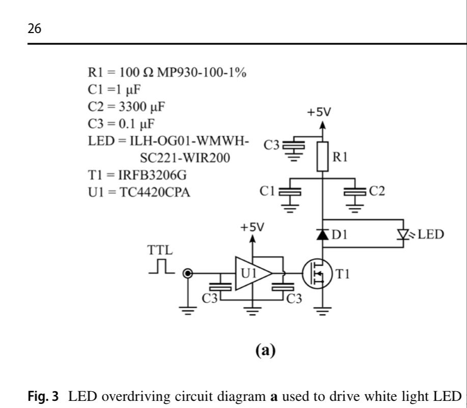
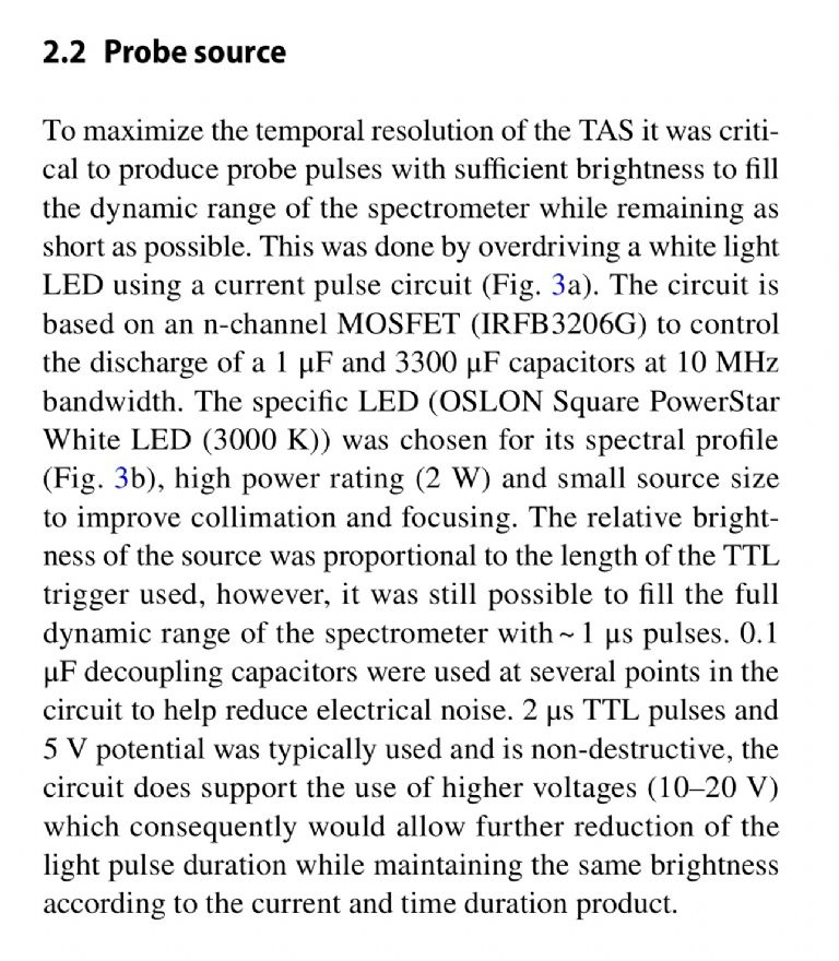
I recently found a simple circuit, which forms part of a more complex instrument but should be adaptable to serve my requirements:

.
Some of the components [including the expensive, non-inductive, 100ohm resistor] are specified, but the diode and the capacitors are not. … The noteworthy point being that this runs a very high speed pulse-train.
I am therefore struggling to identify appropriate components for my ‘shopping list’
I wrote to the “corresponding author” and he kindly replied … but he “could not recall” what specific components they actually used.
Would the electronics experts kindly suggest what exact components they might use in this innocent-looking circuit ?
My own application will run at a lower repetition-frequency than theirs, but individual pulses will still be in the region of ‘a few microseconds’.
… I presume that propagation delay and ESR will therefore both be significant, and that high-quality will improve the longevity.
Thanks in advance
MichaelG.
Even for a 1MHz rep rate, your do not need fancy resistors, etc…The Resistor is only 100 ohms, so any carbon film 1/2 watt will be just fine. Even a 1/2watt wirewound resistor of 100 ohms will do – it will have an inductance of around 150nh = 1ohm @ 1MHz , which is lost in the noise of the 100 ohms, and way above the pulse rate you might work at.
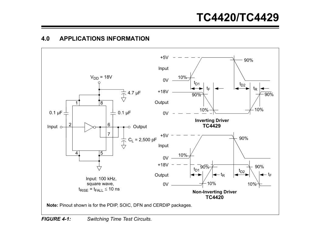
Make C1 a ceramic 1uf, nice and fast, and C2 can be electrolytic. Use 3 x 1000uf and that will reduce the ESR nicely. Ditch C3. That is a typo…U1 is essential.
However, running this circuit at 20Hz is nonsense. The RC time constant of R1-C2 is around 300millisec. 63% of the 5V supply is 3V, which is around the threshold voltage of a typical white led. So the voltage at R1/C2 junction will reduce and stabilise at the LED junction voltage and stay there as the pulse rate is increased. The current through the LED will then only be limited by R1, ie 50mA. Hi current pulse will only be evident below the RC time constant period…This will be modified by the period of pulse to some extent – a very short pulse – 10 of ns, won't discharge C2 completely, so the regulation point will be higher.
You said you want to increase the pulse rate – this will make it worse. For 50Hz rate, you need an RC constant of at least half that, 10ms or so, which would make R1 = 3ohms , making lower pulse rates instantly destructive…
What rate do you want to run at? This sort of circuit is remarkably non-linear – the LED current reduces fast with increase in pulse rate, and is highly dependant on source pulse width.
I think a short description of your final application might suggest a better circuit, or allow tailoring of this one to suite..(avalanche circuits are commonly used for this)
Edited By Joseph Noci 1 on 17/03/2023 06:11:00
Clive Steer.


