Help Identify this Myford 7 lathe

Advert

Help Identify this Myford 7 lathe

Home Forums Beginners questions Help Identify this Myford 7 lathe

Viewing 24 posts - 1 through 24 (of 24 total)
  • Author
    Posts
  • #572722
    Maurits van Dueren
    Participant
      @mauritsvandueren59568

      Hi all

      Being a noob (though I do like watching stuff like Clickspring and This Old Tony), my brother ran into, and gifted me this disassembled Myford lathe. Which appearantly was sitting in this state for a while.

      Right. So first order of business is to figure out what exact model, see if it is complete, etc.

      It came with a photocopied ML7-R manual, but not all parts match. I cannot be sure it is the correct manual.

      Any expert out there that takes one look at the photo's and can tell me what I have or what I may be missing?

      Myford front

      Myford back

      Gearing

      Motor

      Shrouds

      Pully and arbor plate

      <

      Advert
      #11030
      Maurits van Dueren
      Participant
        @mauritsvandueren59568

        I was gifted this disassembled lathe.

        #572791
        Howard Lewis
        Participant
          @howardlewis46836

          Unfortunately, your photos don't open.

          Try again, according to the procedure which the many more expert than I will explain

          Once the pictures ar up there will be lots who can help you.

          Finding the Serial number where it is stamped on the bed should help to identify both Model and date of manufacture. but it might be two different places.

          The cognoscenti will tell you where to look.

          Howard

          #572794
          Thor 🇳🇴
          Participant
            @thor

            Hi Maurits,

            Here is an explanation on how to posts photos on this site.

            Thor

            #572800
            Maurits van Dueren
            Participant
              @mauritsvandueren59568

              Hmm, strange, the photos show up perfectly to me.
              I think the image hosting service is private, so only I can seem them.
              I'll work on reposting or relinking.

              In the mean time, I found the serial on the bed, as well as compared to some more internet video's and it is without doubt a ML7 (non R) build late 1950 (a 100 higher is listed as 1951)

              I found the correct manual, several copies, and one with slightly better resolution then the others.

              I'll start assembling it by the explosion.

              #572805
              Maurits van Dueren
              Participant
                @mauritsvandueren59568

                I told google to allow others to these photos.
                Not sure if they now appear in the original post, but this link should work, including zoom capability.

                https://photos.app.goo.gl/PhPU38GwuNsfqXm77

                Images


                Edited By Maurits van Dueren on 24/11/2021 17:51:35

                #572806
                Maurits van Dueren
                Participant
                  @mauritsvandueren59568

                  Messed that up. Again:

                  Images

                  #572810
                  Steviegtr
                  Participant
                    @steviegtr

                    They show up ok using the http link.

                    If any bits are missing you may find them on ebay. But do a good search as there's a lot of dealers, who strip them.

                    Just to sell the parts at a high price.

                    Steve.

                    #572839
                    Maurits van Dueren
                    Participant
                      @mauritsvandueren59568

                      I went through the whole top-slide carriage assembly exploded view, and all bags of parts. It seems I am missing both feed screw sub-assembly. Both feed-screws, feed-screw nuts, one micrometer dial and both ball-handle assembly are missing.

                      Pretty sure they all ended up in the same bag, and over time that bag got separated from the lathe. I know where the lathe came from, but there is not much chance that is going to turn up.

                      Also the actual clamp is broken, and it was not the original clamp anyway. But I suspect that would have been upgraded afterward anyway.

                      #572846
                      Mike Poole
                      Participant
                        @mikepoole82104

                        Your lathe is a Myford ML7 which is different from the ML7R. The ML7 was produced by Myford from around 1946 until about 1979 when Myford consolidated their 7 range to the ML7R which was a non power crossfeed super 7 with some Super 7 features deleted, the main parts that were deleted were the clutch, and the Super 7 cross and top slide, it also lost the leadscrew handwheel. It is possible to add or upgrade the ML7R to the original Super 7 specification but the power crossfeed is not a cost effective upgrade as the entire saddle and lead screw need replacing. The ML7 that you have would have been grey originally and I not think the factory ever produced them in green. Many parts can be sourced from Myford who are not the original company but one that purchased most of the stock and rights to the name and designs from the original business, although a separate company they have strong connection to RDG the tool supplier. Many lathes get dismantled and the parts sold on eBay so you should not have much trouble with most parts. The white metal bearing shells are long out of production and the repair was to fit a new hardened spindle and phosphor bronze shells but I think this is out of stock and if required you would have to contact Myford to see if they intend to restock. For a lathe that has been out of production for 44 years the spares situation is pretty good.

                        Mike

                        The spindle kit appears to be available but it’s not cheap.

                        Edited By Mike Poole on 24/11/2021 22:50:50

                        Edited By Mike Poole on 25/11/2021 18:17:51

                        #572952
                        Maurits van Dueren
                        Participant
                          @mauritsvandueren59568

                          Thanks everyone.

                          It is definitely a ML7, from 1950. And I identified almost all loose parts in the loose bags.

                          Ignoreing some generic bolds, nuts, washers, these are specific parts I have left (see photos)
                          Maybe someone recognizes them? On the next posts some more detail on the specific items in these photo's

                          20211125_174422.jpg

                          20211125_174441.jpg

                          #572954
                          Maurits van Dueren
                          Participant
                            @mauritsvandueren59568

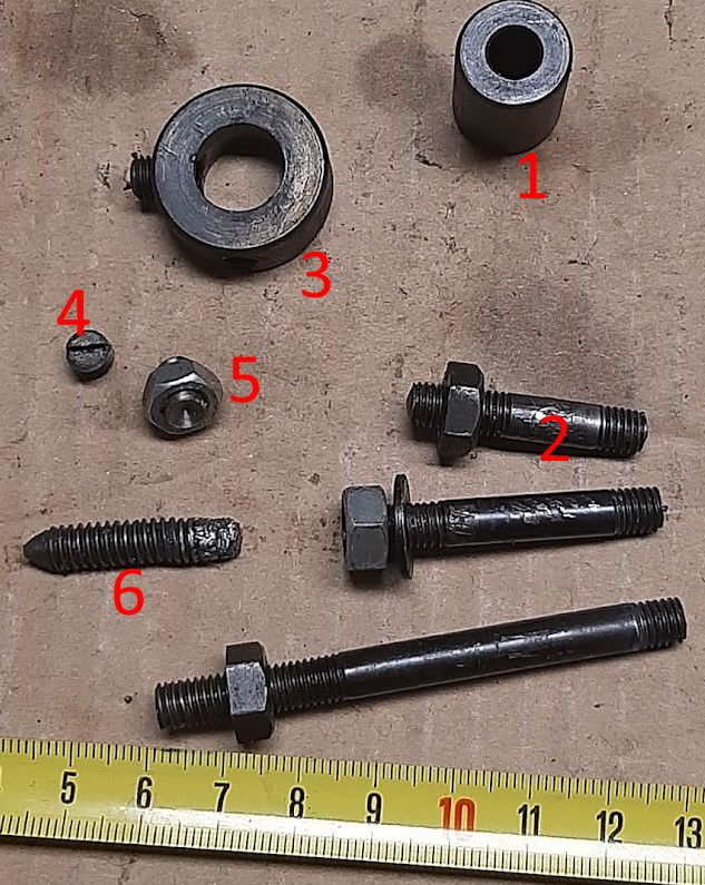
                            I cannot find collar 1 on any exploded view
                            I mean, it could be A51 in the geartrain, but that is not disassembled and appears complete.
                            So where other then in the geartrain would a part like this be?
                            It is 1/4 inch inner diameter, 1/2 outer, and 7/8 high

                            The 3 studs number 2 are 1/4 diam and 1+1/4; 1+5/8; 2+7/8 long
                            On one of them someone jammed an incorrect M6 nut
                            I don't know where they are supposed to go.

                            #572955
                            Maurits van Dueren
                            Participant
                              @mauritsvandueren59568

                              The trust-collar 3 has not one, but two places for a set-screw, at a 90 degree angle
                              I think it may be F34 in the motor assembly, but I am not quite sure how it goes together with F36 and F18
                              Is F18 the short stubby 1/4×1/4 flat point set screw labeled 4 in the picture?
                              And even this collar is F34, what is its function? In that position, it is not a trust collar.

                              I do not know where 5 goes
                              Special about it is it looks like a set screw, but is cupped instead of pointy

                              6 is is a shewed up, coarse thread pointy stud (or broken bold) bold.
                              I was thinking it could be for the main motor pulley, but that is a 3/8 screw
                              It could also be for the triple pulley on the same axel. But being shewed up, I do not want to force it in there.

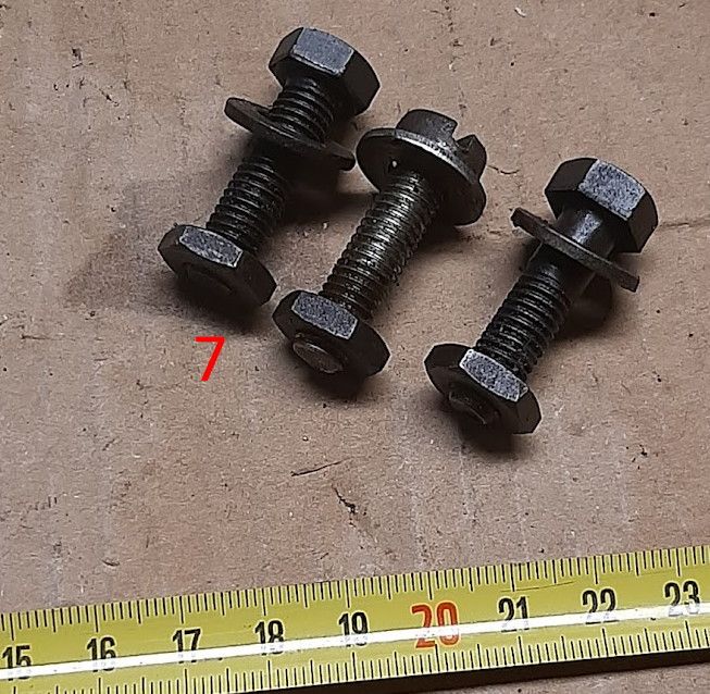
                              7 are 3 generic screws, 3/8 x 1+3/4. One seems non-original.
                              But I was hoping the half-height nuts would trigger someones memory.

                              #573027
                              DiogenesII
                              Participant
                                @diogenesii

                                Collar 1 looks like F35 Tie Bar Spacer

                                The longest stud looks like F37 – don't know about the other two, will become clear during assembly, I guess..

                                F34 fits on the Eccentric Shaft F47, where it is secured with the screw – the other hole accepts a threaded pin F36 which acts as a positive stop for the Swing Head Assembly.

                                5 looks like a threaded oil nipple, I don't know where it goes, sorry.

                                6, ?

                                Are two of the screws F39?

                                #573028
                                DiogenesII
                                Participant
                                  @diogenesii

                                  Discussion of purpose and Dimensions of F36 Stop Peg here;

                                  Thread; 'ML7 Stop Peg'

                                  #573053
                                  Maurits van Dueren
                                  Participant
                                    @mauritsvandueren59568

                                    Thanks

                                    1 F35 Tie bar spacer is correct (actually, I had found that I needed it there yesterday) The tie bar itself is non-original but it fits.

                                    2 F37 also seems correct on the exploded view. But in reality I do not know where it goes. There is no place. No threaded hole. What is it supposed to do? It's just a set of parts floating in the middle of the exploded view.
                                    I am vaguely thinking it is needed to hold up the shroud, and thus probably also the other 2. But I am not looking too closely at the shrouds at this moment.

                                    7 Both F39 are already in there.

                                    5 is definitely not an oil nipple. Not hollow. Just a 3/8 long set screw with a weird concave point.

                                    3 You are probably right about F34/F36 (I did find part F36 also) but it is still not quite clear to me what it does. The whole belt tensioner works quite well already. Maybe it will become clearer when I do final assembly. I think I am about ready for that anyway

                                    Or at least, that part of the lathe. Still missing both top and cross lead screws/nuts/dials/handles. That is a bit of a bummer, because not cheap, and rather essential.

                                    I guess I will just start to actually assembly anyway. I think I know enough now to not completely mess it up. At least get the chuck spinning and the saddle moving.

                                    Thanks

                                    #646354
                                    Maurits van Dueren
                                    Participant
                                      @mauritsvandueren59568

                                      Just a (overdue) followup: Got it all assembled and working last year, picking up on the hobby now:

                                      #646360
                                      speelwerk
                                      Participant
                                        @speelwerk

                                        Looks fine but for safety do fit a countershaft belt guard. Niko.

                                        #646363
                                        Thor 🇳🇴
                                        Participant
                                          @thor

                                          Well done Maurits.

                                          Thor

                                          #646371
                                          DiogenesII
                                          Participant
                                            @diogenesii

                                            Looks like you did a fine job, Maurits, nice to see it complete.

                                            #646393
                                            Maurits van Dueren
                                            Participant
                                              @mauritsvandueren59568

                                              @speelwerk You know, I had completely forgotten about the guard,

                                              The problem was/is, I have only half of it. The outer guard I have, but not the inner shield to which it is mounted. So I put the outer guard to the side, and it slipped my mind.

                                              The lathe did come to me in parts, and has been in parts for who knows how long, perhaps decades. I had to collect several other parts, but the shield was never 'essential' so not high on the list.

                                              I may need to make a bracket of some sort.

                                              #646415
                                              Hopper
                                              Participant
                                                @hopper

                                                Looks like you have done a lovely job. It looks good in the green.

                                                You have the most important guard, the one near your face and left sleeve over the step pulleys. The other one is well out of the way and lots of people run without it. It is handy to be able to grab the (stationary!) large pulley to rotate the chuck when using taps and dies in the lathe. I have thought about removing mine on my ML7 for that reason, having grown used to it on my unguarded old Drummond. But in the end made a spindle crank handle instead, which works even better.

                                                #646417
                                                Howard Lewis
                                                Participant
                                                  @howardlewis46836

                                                  A beautiful job indeed!

                                                  Just be very careful to keep hands, clothes, hair and clths awqay from the unguarded pulley. Otherwise, fabricate the other half of of the gaurad and fit the complete assembly.

                                                  It would be a major disaster to slip or stunble and grab a rotatingb pulley to save yourself!

                                                  Many hours of pleasure, using the lathe, lie ahead of you.

                                                  Howard

                                                  #646436
                                                  ega
                                                  Participant
                                                    @ega
                                                    Posted by Hopper on 25/05/2023 06:32:00:…It is handy to be able to grab the (stationary!) large pulley to rotate the chuck when using taps and dies in the lathe….

                                                    My mill/drill has a flywheel on top of the spindle which is used for the same purpose.

                                                  Viewing 24 posts - 1 through 24 (of 24 total)
                                                  • Please log in to reply to this topic. Registering is free and easy using the links on the menu at the top of this page.

                                                  Advert

                                                  Latest Replies

                                                  Home Forums Beginners questions Topics

                                                  Viewing 25 topics - 1 through 25 (of 25 total)
                                                  Viewing 25 topics - 1 through 25 (of 25 total)

                                                  View full reply list.

                                                  Advert

                                                  Newsletter Sign-up