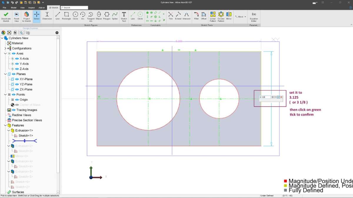
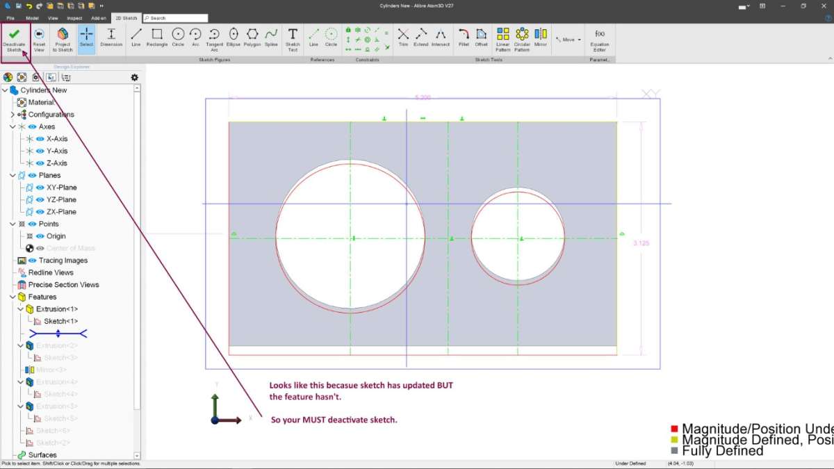
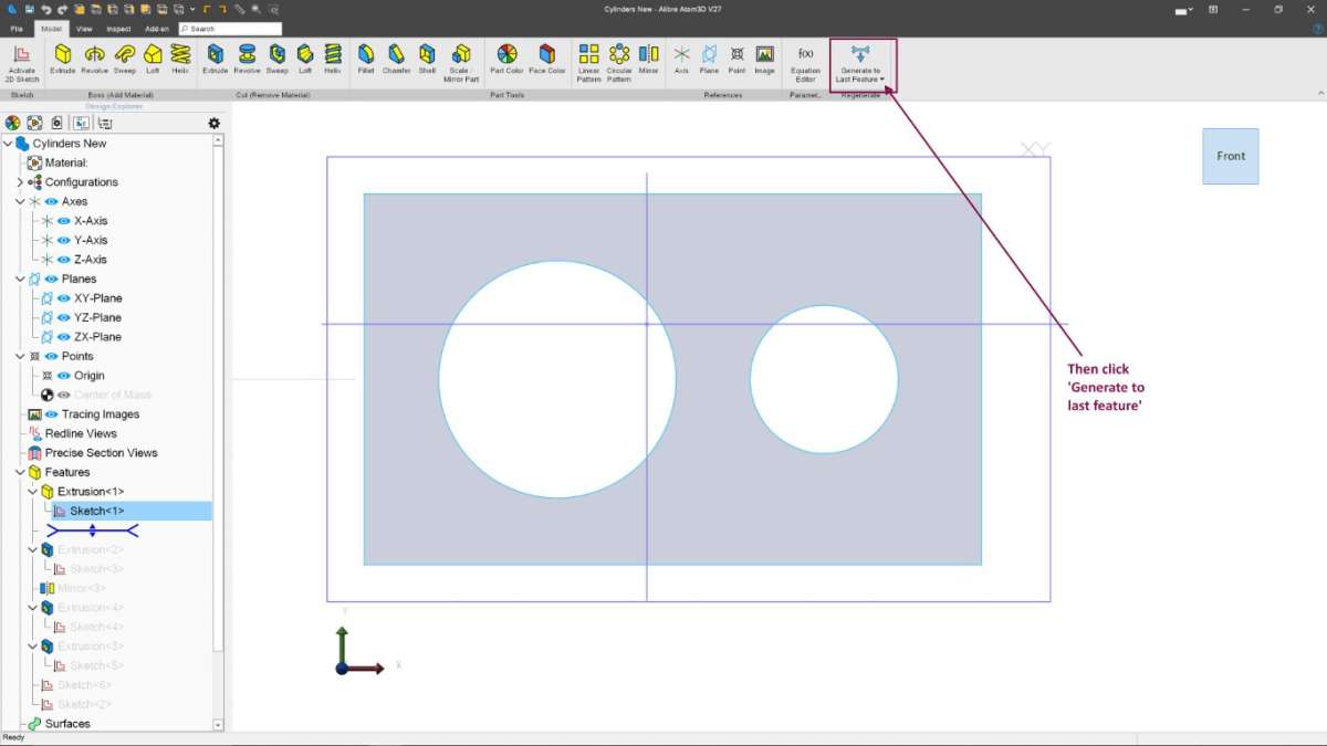
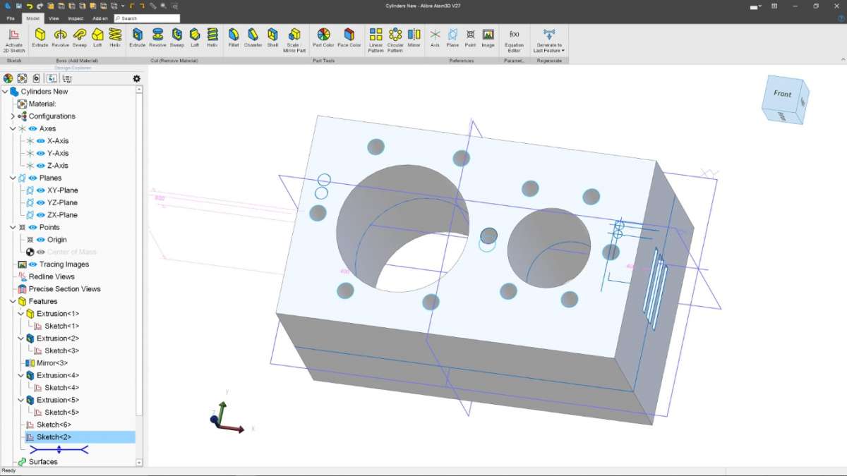
Help! Alibre: Changing Part Size?
Help! Alibre: Changing Part Size?
- This topic has 27 replies, 6 voices, and was last updated 6 November 2023 at 20:52 by
 Nigel Graham 2.

- Please log in to reply to this topic. Registering is free and easy using the links on the menu at the top of this page.
Latest Replies
-
- Topic
- Voices
- Last Post
-
-
Speed camera
1
2
Started by:
David George 1
in: The Tea Room
- 22
-
3 July 2025 at 23:51
not done it yet
-
Bentley BR2 Rotary Aero Engine
Started by:
notlobgp14
in: Miscellaneous models
- 2
-
3 July 2025 at 21:48
notlobgp14
-
Starrett micrometer.
Started by:
Graeme Seed
in: Workshop Tools and Tooling
- 5
-
3 July 2025 at 21:25
peak4
-
Hemmingway rotary broaching kit
Started by:
YouraT
in: Workshop Tools and Tooling
- 1
-
3 July 2025 at 21:21
YouraT
-
Boxford lathe & vertical mill VFD conversion help with start stop
Started by:
Andrew Schofield
in: Beginners questions
- 2
-
3 July 2025 at 21:18
Robert Atkinson 2
-
Firth Valve Gear
Started by:
Andy Stopford
in: Traction engines
- 10
-
3 July 2025 at 21:14
Andy Stopford
-
A grasshopper of unknown vintage
Started by:
mikemunson
in: Stationary engines
- 3
-
3 July 2025 at 20:21
Charles Lamont
-
New (but well aged) member
Started by:
mikemunson
in: Introduce Yourself – New members start here!
- 4
-
3 July 2025 at 19:55
noel shelley
-
New member from Lancashire
Started by:
mannyroad
in: Introduce Yourself – New members start here!
- 7
-
3 July 2025 at 19:14
notlobgp14
-
Bearing boxes for ball race
Started by:
Paul McDonough
in: Beginners questions
- 10
-
3 July 2025 at 18:35
Paul McDonough
-
Twin Engineering’s heavy mill/drill quill removal
Started by:
Martin of Wick
in: Manual machine tools
- 10
-
3 July 2025 at 17:53
David George 1
-
Loctite axles
Started by:
steve2250
in: General Questions
- 5
-
3 July 2025 at 12:22
parovoz
-
Comments (constructive) on the New Forum Software
1
2
…
34
35
Started by:
JasonB
in: New Forum Software questions, comments and Test Threads
- 134
-
3 July 2025 at 10:25
Emgee
-
Grimsby & Cleethorpes MES on the BBC
Started by:
Chris Crew
in: The Tea Room
- 1
-
3 July 2025 at 08:51
Chris Crew
-
Injectors
Started by:
pansy123
in: General Questions
- 6
-
3 July 2025 at 07:05
Dave Wootton
-
Pattern Makers Vice
Started by:
Vic
in: The Tea Room
- 7
-
2 July 2025 at 21:51
KEITH BEAUMONT
-
J&S grinder – belt which way ?
Started by:
gerry madden
in: Manual machine tools
- 7
-
2 July 2025 at 21:44
not done it yet
-
Meddings MF4 Manual
Started by:
Richard Kirkman 1
in: Help and Assistance! (Offered or Wanted)
- 11
-
2 July 2025 at 21:38
Richard Kirkman 1
-
Haining vertical dairy engine boiler.
Started by:
apprentice
in: Beginners questions
- 3
-
2 July 2025 at 20:52
JasonB
-
Motor won’t start
Started by:
Rowan Sylvester-Bradley
in: Beginners questions
- 9
-
2 July 2025 at 17:30
larry phelan 1
-
IME Watchmakers lathe
Started by:
Greensands
in: Manual machine tools
- 11
-
1 July 2025 at 21:41
Dave S
-
Request for a Slot to be Milled in a Shaft
Started by:
James Alford
in: Help and Assistance! (Offered or Wanted)
- 9
-
1 July 2025 at 21:03
bernard towers
-
The Stevenson Trophy – Entries Invited
Started by:
Neil Wyatt
in: Website Announcements
- 1
-
1 July 2025 at 18:44
Neil Wyatt
-
The Bradford Cup – Nominations Wanted
Started by:
Neil Wyatt
in: Website Announcements
- 1
-
1 July 2025 at 18:41
Neil Wyatt
-
FreeCAD v1.0 tutorials
1
2
3
Started by:
Michael Gilligan
in: CAD – Technical drawing & design
- 12
-
1 July 2025 at 18:31
Speedy Builder5
-
Speed camera
1
2
Latest Issue

Newsletter Sign-up
Latest Replies

