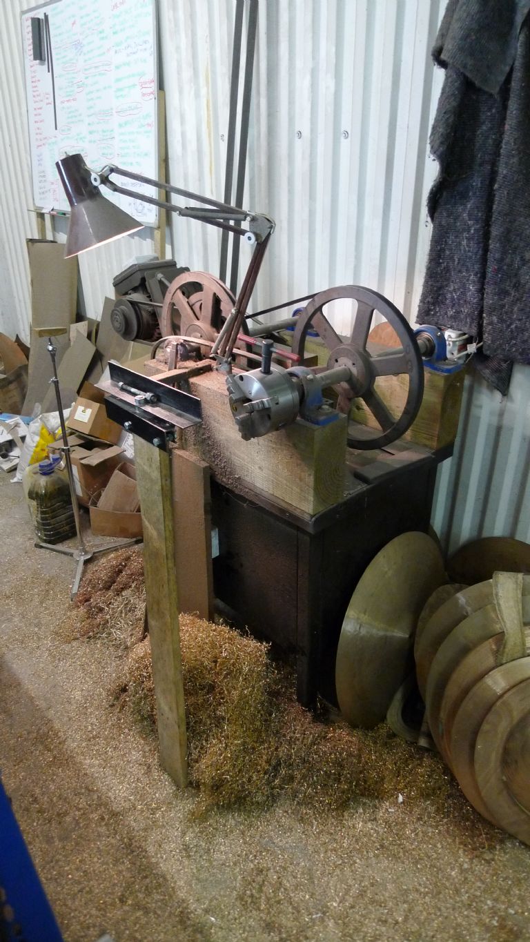
I had some old pictures of the cymbal lathe already on the computer from when I first built it.

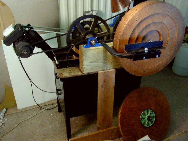
It looks nice and clean there! Not any more. I have since added a post under the tool rest to give a little more rigidity. It is not totally rigid though and nor is the way you lathe a cymbal. The carbide bit (a re-ground roughing tool) is held in a 4 foot or so long piece of square section tube and is levered against the tool rest with the far end under one's armpit, or in the left hand (I'm a leftie), a bit like a very steep snooker shot, the right hand stabilising the fulcrum. The cutting bit rides on the surface of the cymbal, taking a cut but following the contours, it is not rigidly fixed. The swarf comes off in ribbons to about eye height 
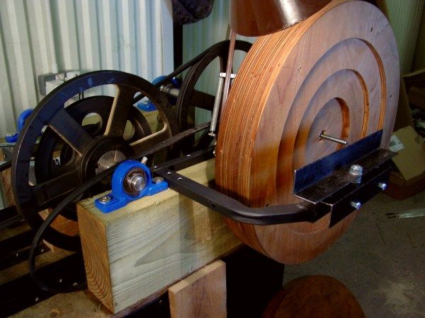
The wooden backing plate which is fitted in the photo above is concave for supporting cymbals while you lathe the underside. The other one, on the floor in front, is flat and used when lathing the top side of the cymbals. Most cymbal profiles will fit in these backing plates, but I also have some wooden rings which slot in to change the shape if necessary.
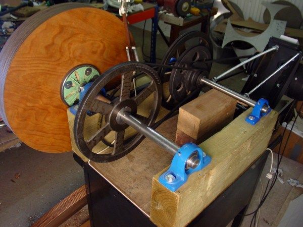
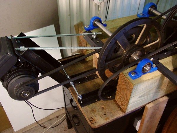
I made this not being certain of cutting speeds and also aiming at multiple materials. The lathe has 6 speeds by means of all combinations of the 2 pulleys on the motor and the 3 on the intermediate spindle. Ranges from 60rpm to 300rpm. Mostly, with cymbal bronze, I am using 300rpm or occasionally the next one down. At some point I want to fit an inverter / speed control with a foot pedal then I can spend less time changing belts/pulleys and also be able to speed up at the centre of cymbals and slow down a bit for the outermost portions of cymbals above about 20 inch diameter.

Pillow block bearings on railway sleeper on an old heavy duty metal filing cabinet type thing which was my dad's, probably was my grandad's too. Myford face plates for attaching the backing plates. Emergency stop kick board across the bottom at the front, but it takes so long to stop because of the momentum, it is a bit of a joke.
The rest of the metal parts of the lathe besides the off-the-shelf pulleys and bearings are mostly bits of 1950s bed frame (the angle-iron) and a TV stand (remember when TVs were properly big and heavy?) I had a nice man with a regular lathe and other machinery make the two spindles for me with keyways and the thread on the main one. Stainless steel.

The bit of M10 threaded bar sticking out of the middle threads into the spindle. That's for holding the cymbal in place through the cymbal's 1/2" mounting hole. Occasionally I might re-work a vintage cymbal for someone. Some of those have smaller holes. I have a little conical nut made from part of an expansion bolt. You can remove the M10 bar to change the backplates or occasionally swap it for a longer one for very high profile cymbals.

The motor can swing in and out and also slide from side to side a bit, so the primary belt can be positioned wherever suits. There's a knack to getting the tension right! The M12 threaded bar is in compression, the M10 is in tension.
There you have it.
Cheers,
Matt.
Matt Nolan 1.


