helical lathe update

Advert

helical lathe update

Viewing 21 posts - 1 through 21 (of 21 total)
  • Author
    Posts
  • #361480
    john constable
    Participant
      @johnconstable10725

      After lots of advice from this forum and cnc zone, I thought I'd update you and invite comments. I decided to build a small prototype to test the principle and 'learn the ropes' and see where all the critical areas are before commiting to a 'MarkII' final version.>>

      I'm at the stage now where I'm trying to make sense of driver boards, controllers and arduinos and so on.>>

      s a relatively simple thing for turning wooden spindle spindles with barley twists, rope twists, hollow spirals and so on – left hand and right hand. Work size max 2" diameter by 10". It's similar in function to a small metalworking lathe with the ability to cut threads. I'm not using a metal lathe partly because of the cost, partly because i don't need the extra functionality and partly because the changes needed (to the spindle drive and gearing) are proving impractical for me.>>

      It's basically a 3-axis machine. X axis for moving the tool (a dremel-type tool) along the length of the spindle in the chuck, a Y axis to advance the tool into the wooden spindle and a z axis which is the rotation of the chuck (slow speeds for positioning not fast for cutting). There will be a 4 th axis for minor adjustments to the height of the cutting tool.

      The x and y axes are a small x-y milling table,the rotation z axis is a small rotary table, mounted vertically, and 4-jaw chuck. The 4th tool-height adjustment axis will be a small scissor lift lab table.

      .All axes will be stepper-motor driven, probably nema 17 bipolar. I'm still learning about driver boards so I haven't decided on them yet.

      So for the front end software, I don't need anything too sophisticated. I'm not sculpting in 3D. I just need to:

      rotate the spindle slowly and continuously
      move the tool along the spindle at a specific speed
      sync those two movement to cut a helix
      advance the tool into the work slightly on each pass

      I will also need to:
      take into account end stops
      rotate the spindle c/w and cc/w for right and left hand threads
      vary the speed of the x movement during a cut to vary the pitch of the helix in a spindle.(excited about that one.)

      A preview of the result would be good bit I think I basically need to enter an x to z ratio (where x might be variable and z might be negative, a depth, a start and end position and an overall cutting speed.

      As you can probably tell i'm new to all this so any advice or observation offered will be gratefully received….>>

      Edited By JasonB on 10/07/2018 15:30:50

      Advert
      #15190
      john constable
      Participant
        @johnconstable10725
        #361484
        Martin Connelly
        Participant
          @martinconnelly55370

          You don't need to rotate the spindle ccw for left hand threads. Lathes do left hand threads by moving the tool away from the chuck instead of towards it. You may end up catering for spindle rotation you don't need.

          Martin C

          #361486
          john constable
          Participant
            @johnconstable10725

            good point! It's just down to the tool movement,of course. And of course on a normal lathe reversing the spindle would be a bit dodgy unless you invert the tool and nearly everything else so I should have realised.

            I think I got caught up in this notion because I've seen these in 'carving' mode rather than 'turning' mode where they dodge backward and forwards in both directions all the time. Maybe that'll be useful to have one day but not needed at the moment.

            #361487
            SillyOldDuffer
            Moderator
              @sillyoldduffer

              The job isn't very demanding in terms of compute power or pins, so I think a Nano will do the job.

              There are two types of controller:

              • the first is more basic and requires some circuitry & setting up of electronics. There is a standard library.
              • the second controller is more sophisticated and can be controlled directly by the Arduino. Simple enough to program but I don't think there's a standard library. I'd recommend this approach.

              Pin count is important, the Nano has 20. The second type of controller requires three inputs. They are:

              1. Enable can be controlled by an Arduino pin or permanently wired ON
              2. Direction (forward or reverse). Probably has to be controlled by an Arduino pin.
              3. Step (Moves the motor 1 step). Must be controlled be an Arduino pin. The Arduino controls speed by varying the pulse-rate, and the distance moved by counting pulses. No pulses and the motor stops.

              I'd permanently wire ENABLE (or connect it to an emergency stop button), so 6 Arduino pins are needed to control the x,y, & z motors.

              You also need pins for the control interface. Choices include:

              1. A 2×16 character display with 5 push buttons like this. It needs 8 pins.
              2. A stand-alone 2×16 display ( or 4×20 ), with an I2C interface it needs only 2 pins, plus a push-button membrane keypad ( 8 pins, unless you can find an I2C version; if so this can share the same pins as the display.)
              3. A TFT Display; these combine input & output on a graphics screen but need a lot a pins. A Nano doesn't have enough, use a Mega.  More complicated to program.
              4. Control the Arduino from a connected PC. Need to understand two different platforms. Complicated and you may not want a PC in your mucky workshop.

              Option 1 typically uses the 5 buttons for data entry using some sort of nested menu system.

              Option 2 has 16 buttons, which will make the interface more human friendly.

              You may want extra pins to detect running out of room, and for a dedicated stop/go button, say 3 pins. So Option 1 would need a total of 17 pins, and the Nano has 20. There are ways of increasing the effective number of pins available to the Nano but they require additional electronics and programming best avoided on a simple project.

              Driving three motors with an Arduino calls for a programming trick. It's trivially easy to drive one motor by using a built in delay() function to set pulse lengths. The technique doesn't work with two or more motors because delay() stops everything. To keep two or more motors stepping together, you have to program the Arduino to emit motor pulses after a certain time has elapsed whilst continuing to service everything else. This is more advanced programming than waking up after given time-delay.

              Designing & programming the control interface will be more complicated than driving the motors. You have to enter data, allow corrections, and provide stop/go control. Once the data has been entered, the code has to do the necessary maths to move the three motors in step. Depending on the form of the helix, the maths might be quite demanding (for the programmer, not the computer). Producing a screw-thread is easy, I'm not so sure about a rope form table leg, where the tool point has to follow a curved path within the helix. Definitely do-able, I don't know how.

              Final point, you said "I don't need anything too sophisticated. I'm not sculpting in 3D." Albeit in simple form, I think you are! A mechanical helix turner would follow a template made by a toolmaker. The Arduino eliminates the toolmaker and cam-following problems, but needs to have a numeric template instead. However, once it can follow a numeric profile, it really is a 3D sculptor. No reason why it wouldn't cut splines and grooves just as well as helices.

              I've probably made it sound complicated. Taken step by step it's achievable.

              Dave

              Edited By SillyOldDuffer on 10/07/2018 17:15:44

              #361500
              JasonB
              Moderator
                @jasonb

                I still don't think you are going to get a twist profile by moving the tool once along the helix. It will only work that way if the diameter of the toolbit is equal to the pitch of the twist. With a Dremel you won't be able to use a cutter much over 1/4" dia so will need to make multiple passes with the tool moved in X & Y.

                Try drawing it in a 3D CAD program and use helical cut to see what shape you can get with a max 1/4" dia cutter following a helical path and you will see how restricted that will be. With a Dremel you really can't use much more than say a 1/8" ball nose cutter with 1mm stepover which on a 50mm dia 2 start barley twist would need several hundred passes all at slightly different X-Y settings which a good controller and CAm package wil sort out..

                J

                #361505
                john constable
                Participant
                  @johnconstable10725

                  I hear you Jason. I'm not necessarily expecting to do it in a single pass. Material removal amount shouldn't be an issue as I am using a 550w cutter and on smaller spindles of half an inch I only need to cut down 1/4".

                  If it's achieving the shape you are referring to, i'll be using bits like the point cutting roundover bit which gives me the right shape profile and they are available in 1/4". Pen wizard do a rope twist bit which is 1/8".

                  #361506
                  JasonB
                  Moderator
                    @jasonb

                    Yep fine for small dia work but not for your 2" dia stuff unless you want more of a spiral than a twist.

                    It's not so much the power that is the issue it is the chatter you will get trying to take a large cut with a Dremel that can only hole 1/8" dia shank tooling.

                    #361507
                    john constable
                    Participant
                      @johnconstable10725
                      Posted by SillyOldDuffer on 10/07/2018 17:11:23:

                      The job isn't very demanding in terms of compute power or pins, so I think a Nano will do the job.

                      There are two types of controller:

                      • the first is more basic and requires some circuitry & setting up of electronics. There is a standard library.
                      • the second controller is more sophisticated and can be controlled directly by the Arduino. Simple enough to program but I don't think there's a standard library. I'd recommend this approach.

                      Pin count is important, the Nano has 20. The second type of controller requires three inputs. They are:

                      1. Enable can be controlled by an Arduino pin or permanently wired ON
                      2. Direction (forward or reverse). Probably has to be controlled by an Arduino pin.
                      3. Step (Moves the motor 1 step). Must be controlled be an Arduino pin. The Arduino controls speed by varying the pulse-rate, and the distance moved by counting pulses. No pulses and the motor stops.

                      I'd permanently wire ENABLE (or connect it to an emergency stop button), so 6 Arduino pins are needed to control the x,y, & z motors.

                      You also need pins for the control interface. Choices include:

                      1. A 2×16 character display with 5 push buttons like this. It needs 8 pins.
                      2. A stand-alone 2×16 display ( or 4×20 ), with an I2C interface it needs only 2 pins, plus a push-button membrane keypad ( 8 pins, unless you can find an I2C version; if so this can share the same pins as the display.)
                      3. A TFT Display; these combine input & output on a graphics screen but need a lot a pins. A Nano doesn't have enough, use a Mega. More complicated to program.
                      4. Control the Arduino from a connected PC. Need to understand two different platforms. Complicated and you may not want a PC in your mucky workshop.

                      Option 1 typically uses the 5 buttons for data entry using some sort of nested menu system.

                      Option 2 has 16 buttons, which will make the interface more human friendly.

                      You may want extra pins to detect running out of room, and for a dedicated stop/go button, say 3 pins. So Option 1 would need a total of 17 pins, and the Nano has 20. There are ways of increasing the effective number of pins available to the Nano but they require additional electronics and programming best avoided on a simple project.

                      Driving three motors with an Arduino calls for a programming trick. It's trivially easy to drive one motor by using a built in delay() function to set pulse lengths. The technique doesn't work with two or more motors because delay() stops everything. To keep two or more motors stepping together, you have to program the Arduino to emit motor pulses after a certain time has elapsed whilst continuing to service everything else. This is more advanced programming than waking up after given time-delay.

                      Designing & programming the control interface will be more complicated than driving the motors. You have to enter data, allow corrections, and provide stop/go control. Once the data has been entered, the code has to do the necessary maths to move the three motors in step. Depending on the form of the helix, the maths might be quite demanding (for the programmer, not the computer). Producing a screw-thread is easy, I'm not so sure about a rope form table leg, where the tool point has to follow a curved path within the helix. Definitely do-able, I don't know how.

                      Final point, you said "I don't need anything too sophisticated. I'm not sculpting in 3D." Albeit in simple form, I think you are! A mechanical helix turner would follow a template made by a toolmaker. The Arduino eliminates the toolmaker and cam-following problems, but needs to have a numeric template instead. However, once it can follow a numeric profile, it really is a 3D sculptor. No reason why it wouldn't cut splines and grooves just as well as helices.

                      I've probably made it sound complicated. Taken step by step it's achievable.

                      Dave

                      Edited By SillyOldDuffer on 10/07/2018 17:15:44

                      Thanks, David.That's very useful. It'll take me a while to go through that but I can see there's plenty in there I haven't considered yet.

                      I'd like to learn to write g-code at some point but I won't want to enter it with a key pad although it might be interesting to watch progress on a small integrated screen. Even if I only need 3 axes on the prototype I'll want 4 on the MkII so I'll probably put it on the prototype so I can just move everything from the motor to software over on to the MKII.

                      I don't think I saw mention of starting and stopping the tool. Does the controller include that facility?

                      #361508
                      john constable
                      Participant
                        @johnconstable10725
                        Posted by JasonB on 10/07/2018 20:04:04:

                        Yep fine for small dia work but not for your 2" dia stuff unless you want more of a spiral than a twist.

                        It's not so much the power that is the issue it is the chatter you will get trying to take a large cut with a Dremel that can only hole 1/8" dia shank tooling.

                        My dremel is actually a von-haus and it can take a 1/4" shank. The largest of these is 22.2mm diameter cutter which is probably larger than I'd need even on 2" diameter stock.

                        Even so, I think I'm looking at multiple passes to get a cleaner finish and also now you've warned me of the chatter issue.

                        #361509
                        SillyOldDuffer
                        Moderator
                          @sillyoldduffer
                          Posted by john constable on 10/07/2018 20:15:00:

                          Posted by SillyOldDuffer on 10/07/2018 17:11:23:..

                          I'd like to learn to write g-code at some point but I won't want to enter it with a key pad although it might be interesting to watch progress on a small integrated screen. Even if I only need 3 axes on the prototype I'll want 4 on the MkII so I'll probably put it on the prototype so I can just move everything from the motor to software over on to the MKII.

                          I don't think I saw mention of starting and stopping the tool. Does the controller include that facility?

                          G-code. I hadn't thought of using G-code, but good idea, or at least a sub-set of it. There are some examples of Arduino G-code interpreters out there already which will save time if you can adapt one. If g-code is used to program the lathe, then it would make sense to write the G-code on a PC, test it on one of the emulators, and then copy it on to an SD-Card for transfer to the Arduino Then the human interface part of the Arduino program can be simplified. The Arduino has library and hardware for SD Cards.

                          Stepper motor controllers don't have any way of managing a Dremel-type tool, but that's not a problem. Suitable controllers are available. It's another control pin or two: you're creeping up to the 20 limit. Again not an issue, the Mega has a lot more pins if needs must.

                          Dave

                          #361550
                          SillyOldDuffer
                          Moderator
                            @sillyoldduffer

                            Whoops, in a post about G-Code with an Arduino, I forgot to mention grbl.

                            Thinking about G-code last night, I wondered if it might be an over-complication in this case? G-code is a simple language for controlling the movements of a CNC machine. The machine could be a lathe, mill, robot, machine centre or whatever. One benefit is that programmers don't have to learn a new language for each and every machine. Another is that, with care, the same program can be used to make the same object on different machines. Also, emulators and other tools are available that allow the tool path to be tested off-line, reducing the risk of breaking a real machine. There are books, manuals and web tutorials that explain the syntax. Not all of this is useful on a small private project.

                            G-code might be overkill on a home-made helical lathe with a deliberately limited repertoire. The alternative is to code the Arduino to move the motors directly using an instruction set defined by yourself; the program could be much simpler than a proper G-code implementation.

                            One of the nice things about programming is that G-Gode vs home-made can coexist or you can change horses mid-stream. The lathe, stepper motors, power supply and controllers don't change, only the way you program the Arduino. It's very flexible.

                            Dave

                            Edited By SillyOldDuffer on 11/07/2018 09:26:33

                            #361560
                            JasonB
                            Moderator
                              @jasonb

                              One other feature you will want to include is for multi-start "threads" as being limited to smaller cutters you can get a longer helix by using several of them.

                              Using your 1/4" dia cutter as an example shown as the red profile on the right on 1" dia stock these are the results using 1, 2, 4 and 12 starts. The lower numbers end up looking like a rounded screw thread but as the number goes up so does the pitch until you get a spiral and eventually a twist.

                              spiral1.jpg

                              spiral2.jpg

                              spiral4.jpg

                              spiral12.jpg

                              #361635
                              john constable
                              Participant
                                @johnconstable10725
                                Posted by SillyOldDuffer on 11/07/2018 09:24:42:

                                Whoops, in a post about G-Code with an Arduino, I forgot to mention grbl.

                                Thinking about G-code last night, I wondered if it might be an over-complication in this case? G-code is a simple language for controlling the movements of a CNC machine. The machine could be a lathe, mill, robot, machine centre or whatever. One benefit is that programmers don't have to learn a new language for each and every machine. Another is that, with care, the same program can be used to make the same object on different machines. Also, emulators and other tools are available that allow the tool path to be tested off-line, reducing the risk of breaking a real machine. There are books, manuals and web tutorials that explain the syntax. Not all of this is useful on a small private project.

                                G-code might be overkill on a home-made helical lathe with a deliberately limited repertoire. The alternative is to code the Arduino to move the motors directly using an instruction set defined by yourself; the program could be much simpler than a proper G-code implementation.

                                One of the nice things about programming is that G-Gode vs home-made can coexist or you can change horses mid-stream. The lathe, stepper motors, power supply and controllers don't change, only the way you program the Arduino. It's very flexible.

                                Dave

                                Edited By SillyOldDuffer on 11/07/2018 09:26:33

                                Thanks, Dave. I'll consider both. I might go with g-code just because i'd like to learn the language and if I move up to more complex machines it would be good to already have that skill but I can see there are benefits from keeping it simple if that's all that is required.

                                #361638
                                john constable
                                Participant
                                  @johnconstable10725
                                  Posted by JasonB on 11/07/2018 10:28:49:

                                  One other feature you will want to include is for multi-start "threads" as being limited to smaller cutters you can get a longer helix by using several of them.

                                  Using your 1/4" dia cutter as an example shown as the red profile on the right on 1" dia stock these are the results using 1, 2, 4 and 12 starts. The lower numbers end up looking like a rounded screw thread but as the number goes up so does the pitch until you get a spiral and eventually a twist.

                                  spiral1.jpg

                                  spiral2.jpg

                                  spiral4.jpg

                                  spiral12.jpg

                                  Those look really good, Jason. What software did you use to model them with?

                                  I will be doing multi-start threads and hollow threads and also variable pitch threads. All your models seem to use the same width tool for the same thickness of helix. I'll need to model with different widths.

                                  #361645
                                  Neil Wyatt
                                  Moderator
                                    @neilwyatt

                                    I'd consider a subtly different approach.

                                    Consider moving the tool in and out to create a 'cross section' of the twist, then step along, changing the start point by an appropriate amount of twist and repeat, and repeat and repeat…

                                    #361648
                                    john constable
                                    Participant
                                      @johnconstable10725
                                      Posted by Neil Wyatt on 11/07/2018 17:29:27:

                                      I'd consider a subtly different approach.

                                      Consider moving the tool in and out to create a 'cross section' of the twist, then step along, changing the start point by an appropriate amount of twist and repeat, and repeat and repeat…

                                      So effectively build it up in slices as I move along the spindle?

                                      #361656
                                      JasonB
                                      Moderator
                                        @jasonb

                                        That is what I have been talking about with a 1mm or so step over. Not sure which would be best either running along the length or round and round with teh tool going in/out.

                                        Woud be nice if one of the CNC boffins could model a spiral like I drew and then put it into CAM and simulate the toolpath to see what way the machine prefers to cut the shape.

                                        John, I drew it in Alibre but you should be able to do the same with Fusion 360 which is free.

                                        This is the file for F360 if anyone is upto it

                                        #361665
                                        john constable
                                        Participant
                                          @johnconstable10725
                                          Posted by JasonB on 11/07/2018 18:26:12:

                                          That is what I have been talking about with a 1mm or so step over. Not sure which would be best either running along the length or round and round with teh tool going in/out.

                                          Woud be nice if one of the CNC boffins could model a spiral like I drew and then put it into CAM and simulate the toolpath to see what way the machine prefers to cut the shape.

                                          John, I drew it in Alibre but you should be able to do the same with Fusion 360 which is free.

                                          This is the file for F360 if anyone is upto it

                                          I don't think either will give me a very smooth finish compared to relying on the profile of a cutter. Also, with the turning method any backlash in x and y is largely harmless but with a carving method it becomes more of an issue.

                                          #361671
                                          Anonymous
                                            Posted by JasonB on 11/07/2018 18:26:12:

                                            Woud be nice if one of the CNC boffins could model a spiral like I drew and then put it into CAM and simulate the toolpath to see what way the machine prefers to cut the shape.

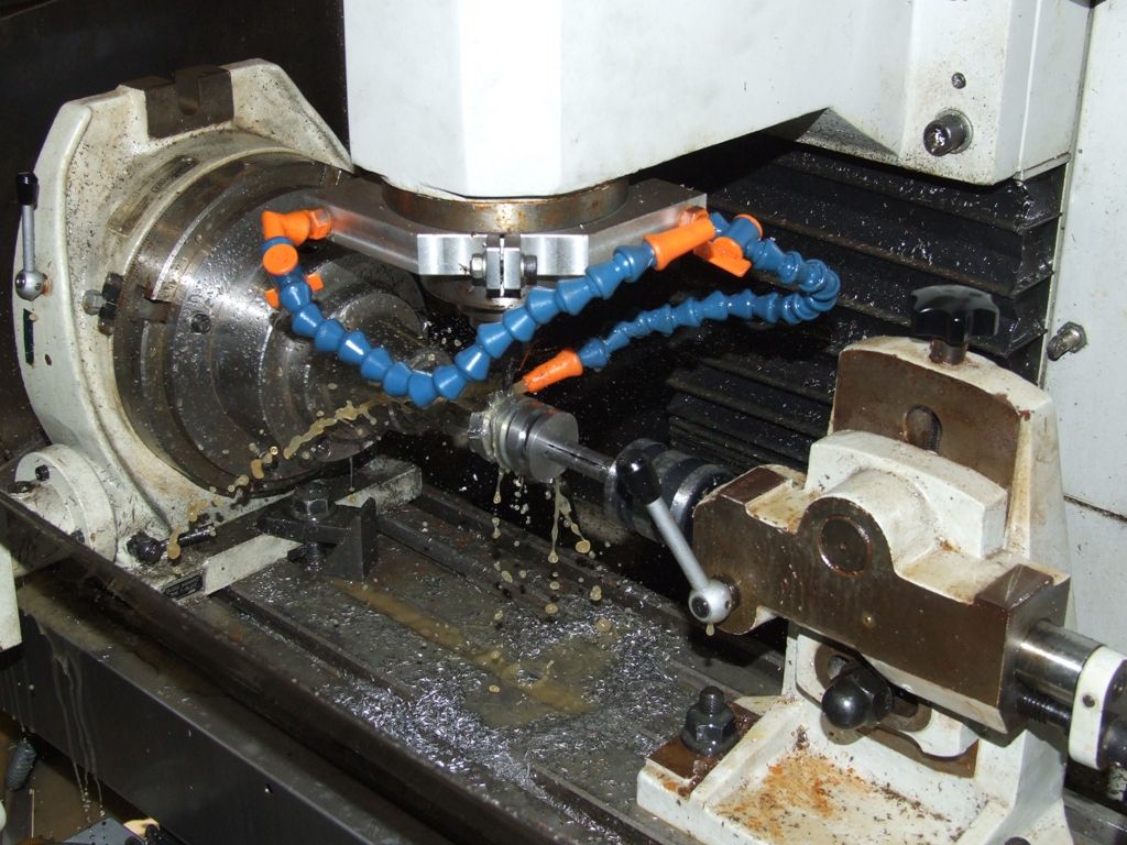
                                            I think you'd need a pretty expensive CAM package to get it to generate sensible code, at least for what is effectively a 4th axis mill. My expensive CAM package only goes up and down and round in steps, or round and round and down in steps in 4th axis mode. Neither of which is ideal for generating helices. When I needed to machine a helix:

                                            worm setup.jpg

                                            I wrote the G-code by hand. The basic helix code is simple:

                                            G01 Xxx.xxx Axxx.xx Fxxxx

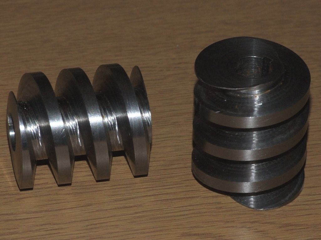
                                            Slight offsets for individual passes were worked out on graph paper. I had all sorts of issues with feedrates, and ended up using inverse time feedrate, G93. The final finish is dictated by the tool rather than the code:

                                            steel worms 1.jpg

                                            Andrew

                                            #361725
                                            JasonB
                                            Moderator
                                              @jasonb

                                              Thanks for the Input Andrew. So sounds like a bisic constant helix is not too difficult but the user would be limited by the profile of the available tools. Any building up of the profile with a small cutter and multiple passes would be a lot more involved.

                                              John, have you got a link to the upto 22mm tool bits you mentioned and if I get time I'll draw up what could be done with one of them. Looks like your "Dremel" is almost a small router or laminate trimmer so should have a bit more guts.

                                            Viewing 21 posts - 1 through 21 (of 21 total)
                                            • Please log in to reply to this topic. Registering is free and easy using the links on the menu at the top of this page.

                                            Advert

                                            Latest Replies

                                            Viewing 25 topics - 1 through 25 (of 25 total)
                                            Viewing 25 topics - 1 through 25 (of 25 total)

                                            View full reply list.

                                            Advert

                                            Newsletter Sign-up