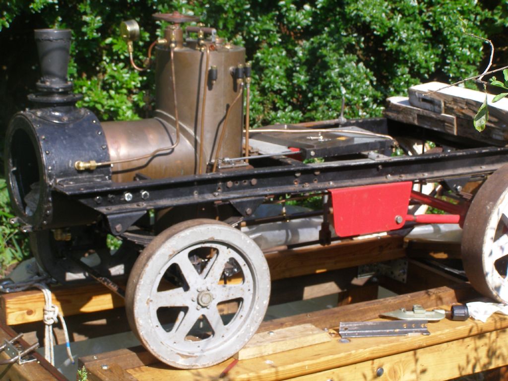
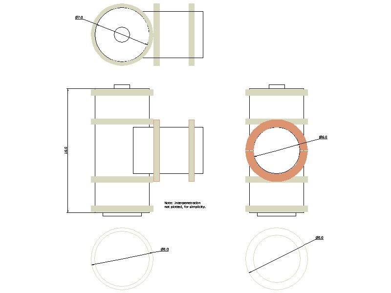
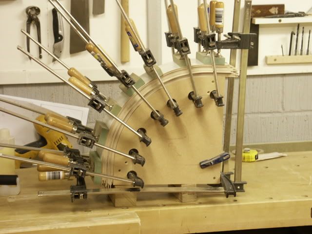
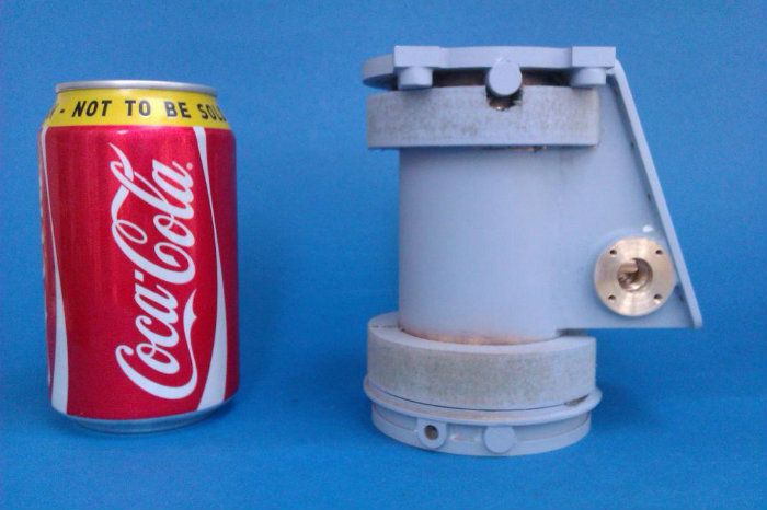
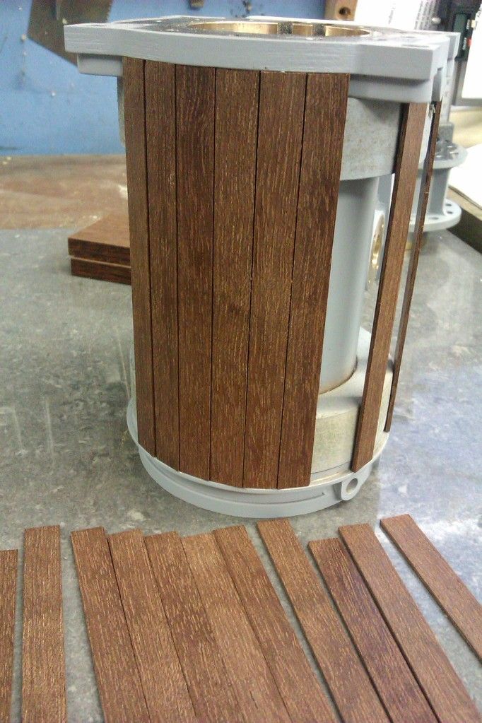
(Yes I know a proper drawing would help but I don't have one! The simplified drawing and photo below might explain things.)
'
My wagon's boiler is an unusual shape, a T-piece with 7" o.d. X 16" high cylindrical outer firebox, and a short 6" o.d. horizontal barrel at half-height. The latter's barrel diameter is level with the chassis rail tops.
The barrel enters for about 1/2" into the 8" o.d. smoke-box, on which a ring of "rivets" (M3 round-head cap-screws) holding the annular channel adaptor-plate narrows the cladding overlap to about 1/4" .
It also needs a cradle fitted to an inverted-arch chassis cross-member, below it, for support if the smoke-box is removed. (as it would be if I needed lift the boiler from the vehicle.)
So cladding is somewhat awkward!
My thoughts:
A wooden half-circumference cradle on the cross-member.
Two rings of 8" od X 6" i.d. on the barrel; the front one helping support the cladding sheet's overlap on the smokebox.
Two pairs of rings 8" o.d. X 7" i.d., each pair above and below the barrel, on the fire-box.
So 6 rings and one half-ring.
Question:
At a working temperature of about 200ºC (90psi), how would these cope:
– ordinary soft-wood, the rings made in 2 or 3 layers of sectors overlapped, glued and screwed together on their faces, and so the grain on each part is not far off concentric, for strength.
– exterior-grade plywood, possibly 2 or 4 layers depending on layer thickness,
– MDF
– ??
All finished turned sub-assemblies then soaked in preservative.
Hi Nigel, I can't help with the types of wood you have listed, but getting a small offcut and checking how it reacts in the oven will be a good indicator. I don’t think you need something that will handle 200DegC.
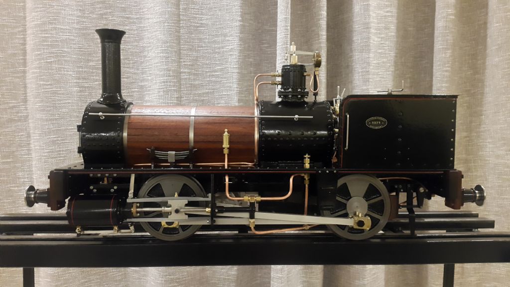
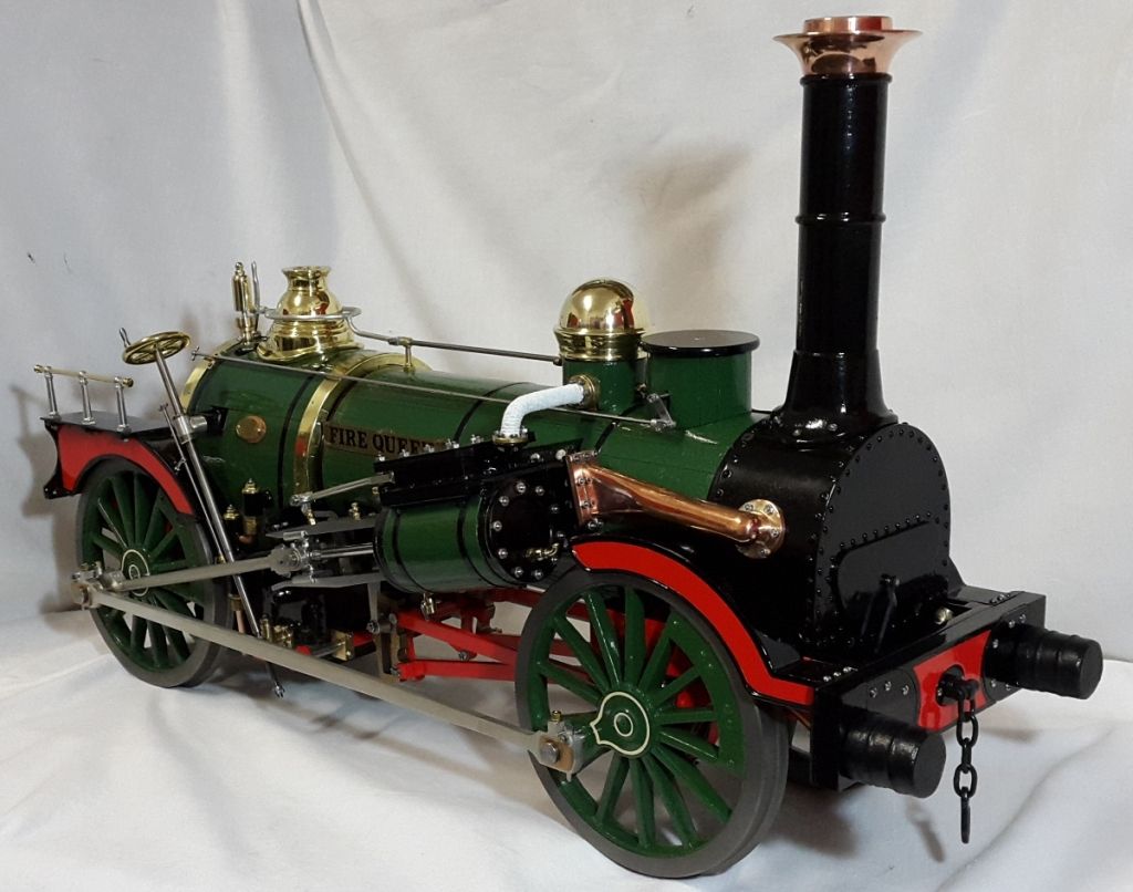
For the cladding I’ve done; I used scrap sleeper wood. It smells and looks like rosewood for these two models. I chamfered the corners and glued the strips to the barrel using RTV silicone. This allowed movement and kept the strips from bowing outwards. Then strapping doesn't really matter. The unpainted wood was treated with linseed oil, and the Fire Queen painted by brush using 2K. Hope this helps….
I have done the spacing rings using thin "aircraft" ply cut into strips and then laminated several of these strips over aformer. Once set the adhesive will stop the ply springing back to flat. Not got aphoto but this is the sort of thing where I have been laminating furniture.
You could just use apiece of your existing tube, laminate say 3/4 of the way round and then you can cut back the ends to make the rings from two halves with a simple halving joint.
I doubt anything wooden will last around the Firebox, OK for the horizontal part of the boiler
I would not us eMDF even exterior grade for this though I have done it in the past for stationary engines as mine just get run on air.
I am wondering if a thin ring of a good insulating material in direct contact with the copper boiler, with the wooden ring outside that, might help. It might also provide some compressibility to cope with heat expansion.
The insulation tends to go between the crinolines. Not really used on the originals as they were fully wood insulated but most models use a crinoline spacers to support the outer sheet cleading and modern Kaowool or similar insulation between
For the firebox I'd be looking at metal for any crinolines.
At a working temperature of about 200ºC (90psi), how would these cope:
– ordinary soft-wood, the rings made in 2 or 3 layers of sectors overlapped, glued and screwed together on their faces, and so the grain on each part is not far off concentric, for strength.
– exterior-grade plywood, possibly 2 or 4 layers depending on layer thickness,
– MDF
– ??
All finished turned sub-assemblies then soaked in preservative.
…
Wood starts to char at about 200°C so that's uncomfortably hot. My main worry at that temperature is the glue – most glues weaken badly when they get hot. Plywood and MDF both contain glue, and performance probably varies by make. I guess the fire-resistant types are better. Ditto heat performance of preservatives – which one?
Does the cladding get as hot as 200°C though? The steam table in Tubal Cain suggests 160°C at 90psi, and probably less than that on a small boiler because a thin layer of wood being a poor insulator tends to keep it cool.
I guess wood and glue are good enough at 160°C, but unreliable at and above 200°C. How long the wood is cooked matters too – big difference between a boiler run for a few hours at weekend, and one steamed all day every day.
I used the waste strips that separate layers in stacked wood for lagging my Burrell running at 160 psi. No preservative except a lot of stray oil. It was inspected at 10 years, did another 6 and is retired for the time being for other reasons. Full size road engines use common pine next to the boiler.
As an alternative, my latest creation uses flanged up ally crinolines. It would avoid glue issues as noted by others. Soft ally sheet is dead easy to flange, you could even try a bit of spinning.
I think it's ordinary wood then. Either crinolines holding soft wadding between them, or strips. The one area I need be careful with is the joint with the smoke-box, for air-tightness, but suitable soft packing such as Kaowool should deal with that.
The glueing I'd mentioned was really for helping hold a built-ring together for turning. Its main fixings would be brass wood-screws.
.
Martin – flanged aluminium. Interesting idea. I don't know how things would behave if any water found its way into the cladding though. I have a tinsmith's jenny for making such items but have not managed to make it work – clearly there is a knack to them I don't know! To flange the top and floor plates for the ash-pan, in 1mm mild-steel sheet, I had to resort to hammer and a former carved from a scrap car brake-disc, leading to flanges that work but are very messy. Fortunately they are hidden inside the pan.
.
I don't know what the original vehicles used. They look as if not insulated at all, so outer cladding sheets on the model will represent that to some extent, and help hide a somewhat gawky problem with the proportions of the boiler itself. I think it's a bit smaller than it should be, leading to problems mounting it in the chassis.
The photographs show the boiler should be bolted together, producing a prominent ring of studs and nuts round the top of the outer firebox. The model version is silver-soldered copper so lacks that, but I am planning to make a top cover for it anyway.
Typical traction engines don't have anything over the fire box or top of the boiler above the firebox. Insulation is only on the round horizontal part of the boiler from throat plate to smokebox. So your waggon boiler would likely have been similar. maybe the top half of the vertical part would be insulated too much like you see on a wood clad vertical boiler where the wood does not extend down to the firebox.
If it is to make the boiler look the right size then just use metal around the vertical part of your boiler and wood/insulation below the cleading for the horizontal part. AOne of the softer aluminium sheets would be quite easy to form over a turned ply or MDF former. If made to a Z section it would be fairly simple to clamp it to the boiler and leave a flange for fixing screws to take the outer cleading.
The Hindley wagon was not built like a traction-engine or overtype steam-wagon, with a flat-sided, arched firebox forming part of the chassis.
Instead it is more like the wagons with vertical boilers, in which the boiler has brackets that sit on a more conventional lorry chassis: long rails supporting the machinery between them.
.
It's not clear if the cylindrical surfaces were lagged on the originals but the flat, circular top of the firebox appears to have been left exposed. The archive photographs showing the wagons under construction or test may have been taken before completion, and the boilers on wagons photographed in service are largely hidden.
However there is just about enough visible collectively to suggest the boiler was clad except for the top plate, and for the whole height of the firebox. If it used wood, the smooth appearance says it was still covered with sheet metal.
That may have been all done before the boiler was craned into the chassis; and it would make sense for me to do that. I have made a special lifting-attachment for use with my travelling-crane, for this boiler.
While lagging may bring the appearance nearer to scale, its primary purpose is still insulation.
.
I need remember not to cover the maker's marks (serial number, CE-mark etc). They are in tiny letters round the foundation-ring just above the front of the ash-pan, about two inches behind the axle, so the Hon. Boiler Admirer will have to lie on the ground, magnifying-glass in hand, if he wants to verify them!
Author
Posts
Viewing 12 posts - 1 through 12 (of 12 total)
Please log in to reply to this topic. Registering is free and easy using the links on the menu at the top of this page.