Has anybody built the flame eater “Nick”?

Advert

Has anybody built the flame eater “Nick”?

Home Forums Miscellaneous models Has anybody built the flame eater “Nick”?

Viewing 25 posts - 101 through 125 (of 246 total)
  • Author
    Posts
  • #241596
    Brian John
    Participant
      @brianjohn93961

      I have a feeling it is the last : grub screw tilting the flywheel. Now this can only happen if the hole is too big or the axle too small (or both) which allows this tilting to happen. I cannot make the hole smaller and I cannot get a bigger axle as they all seem to be 5.97mm. So I am not sure how to proceed from here other than to start again with a new flywheel.

      As for what has caused this : I only have problems with cast iron flywheels wobbling so perhaps in future I should not be reaming cast iron out to 6mm. Perhaps drill to 5.9mm and see how that goes ?

      Advert
      #241597
      pgk pgk
      Participant
        @pgkpgk17461
        Posted by Brian John on 06/06/2016 10:13:11:

        ……. I cannot make the hole smaller and I cannot get a bigger axle as they all seem to be 5.97mm. ..

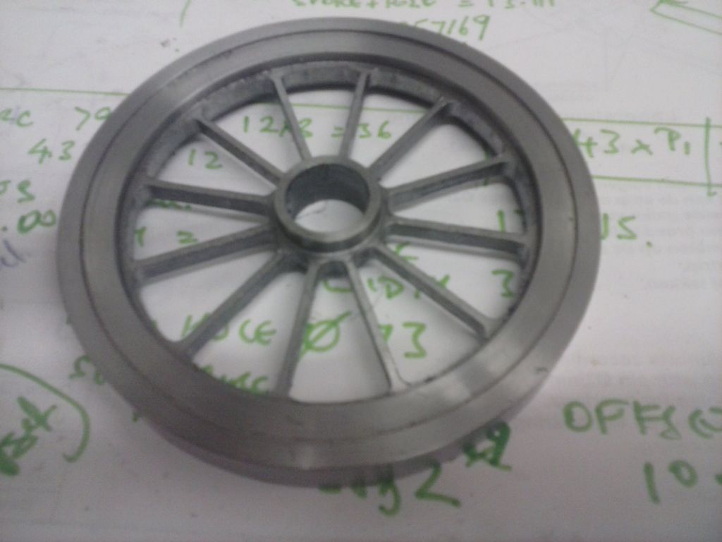
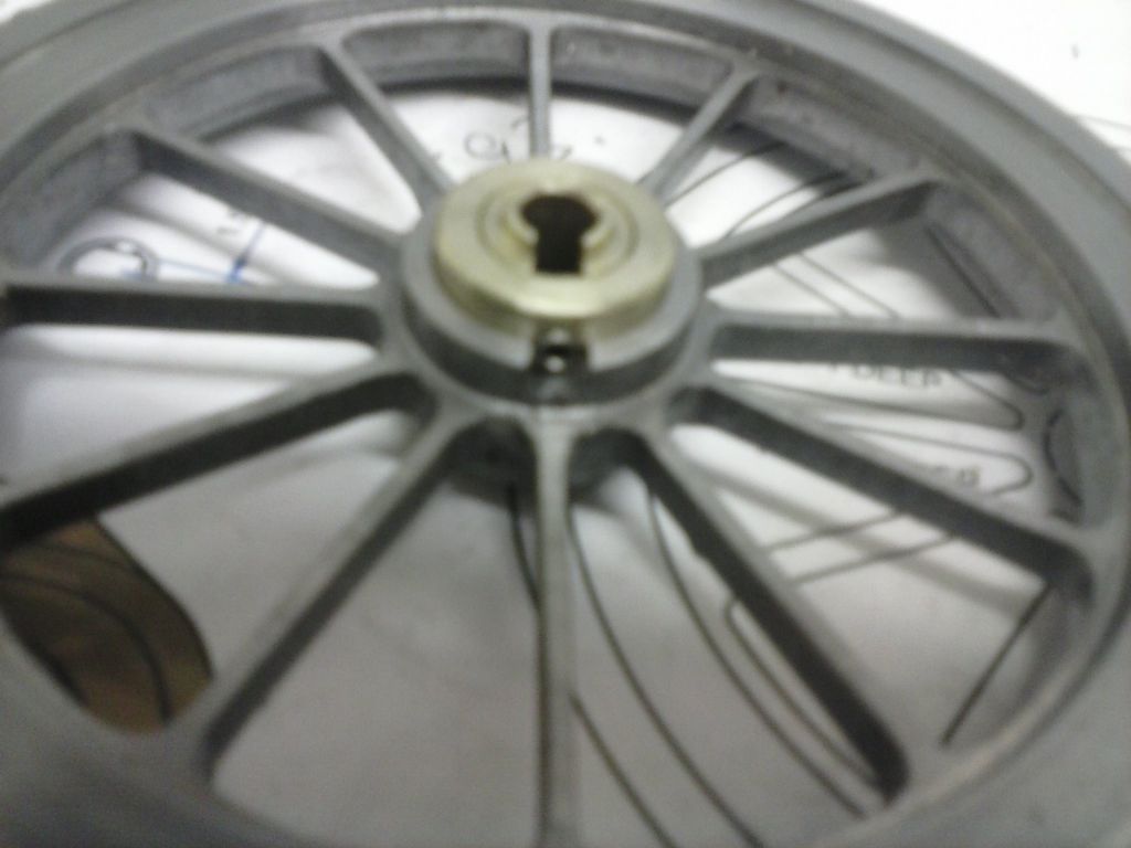
        Remember you have a lathe? Depending on the situation you ought to have the choice of making your own axle, or turning down the end, press fitting a new chunk on there and turning it to fit or even boring a larger hole into the flywheel and fitting a new centre and try again.

        When I made my own flywheel for the stirling the centre was separate to save on stock thickness.

        cam00435.jpg

        cam00483.jpg

        #241600
        JasonB
        Moderator
          @jasonb

          Use a bit of axle material to mount the flywheel in teh lathe as it would be on teh engien and turn it true.

          2 or 3 grub screws spaced around the hub will allow you to tweak the position.

          Also not sure why it is taking so long to polish a small flywheel, after turning use 120grit until all turning marks have gone, then 180grit to remove teh 120marks, then 400 grit if you want a shiny rim. Using too fine a paper and using it too soon will take for ever.

          #241606
          Brian John
          Participant
            @brianjohn93961

            PGK : I have tried turning 6.35mm axles into 6mm axles and it does not work. My lathe is not up to it.

            Jason : I know I shouldn't keep blaming the lathe but I do not get a good finish on cast iron. The best I can get leaves a lot of polishing to be done with 400 grit before moving to 800 and 1500. I have no problem with brass flywheels as I get a good finish in the lathe and I do not have to polish them at all.

            ''A good carpenter never blames his tools '' but is that applicable to model engineers ?

            Edited By Brian John on 06/06/2016 11:15:59

            #241607
            roy entwistle
            Participant
              @royentwistle24699

              Brian 'A good carpenter never blames his tools '' but is that applicable to model engineers ?


              Definitely    

                 Can I suggest  that you make a bush to fit the shaft  and then open the hole in the flywheel and insert the bush using something like Locktite

              Roy

              Edited By roy entwistle on 06/06/2016 11:27:51

              Edited By roy entwistle on 06/06/2016 11:30:29

              #241609
              JasonB
              Moderator
                @jasonb
                Posted by Brian John on 06/06/2016 11:14:06:

                Jason : I know I shouldn't keep blaming the lathe but I do not get a good finish on cast iron. The best I can get leaves a lot of polishing to be done with 400 grit before moving to 800 and 1500.

                Brian, read what I put. Start with something coarser like 120grit. 400 is too fine to start with if you are trying to remove machining marks.

                #241611
                Brian John
                Participant
                  @brianjohn93961

                  Jason : okay, I will start with 120 grit next time.

                  Roy: yes, I am thinking along the lines of some sort of bush. I have just ordered an 8mm hand reamer and a 7.8mm drill bit from China. They will take about three weeks to arrive..

                  #241613
                  Ian S C
                  Participant
                    @iansc

                    As mostly my flywheels are built up from 8 mm hot rolled plate, the hubs are a separate item Loctited in the wheel, early ones were brazed in place. The bush is a top hat shape, the grub screw goes through the thick(brim)part, on the bit that goes through the wheel I put a collar. This one is about 6" with an old crankshaft with a split bush on the 1/4" shaft to fit the 3/8" hole in the flywheel. dsc01251 (1024x768).jpg Ian S C

                    Edited By Ian S C on 06/06/2016 12:27:19

                    #241616
                    Brian John
                    Participant
                      @brianjohn93961

                      Ian : how do you make the slit in the bush (and keep it neat) ? How wide should the split be ?

                      #241761
                      Brian John
                      Participant
                        @brianjohn93961

                        I am a bit fed up with cast iron flywheels so I decided to move onto the main cylinder while I decide what to do about them.

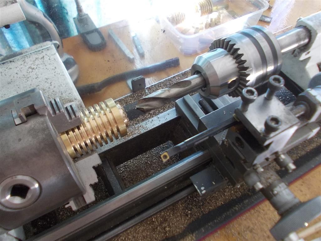
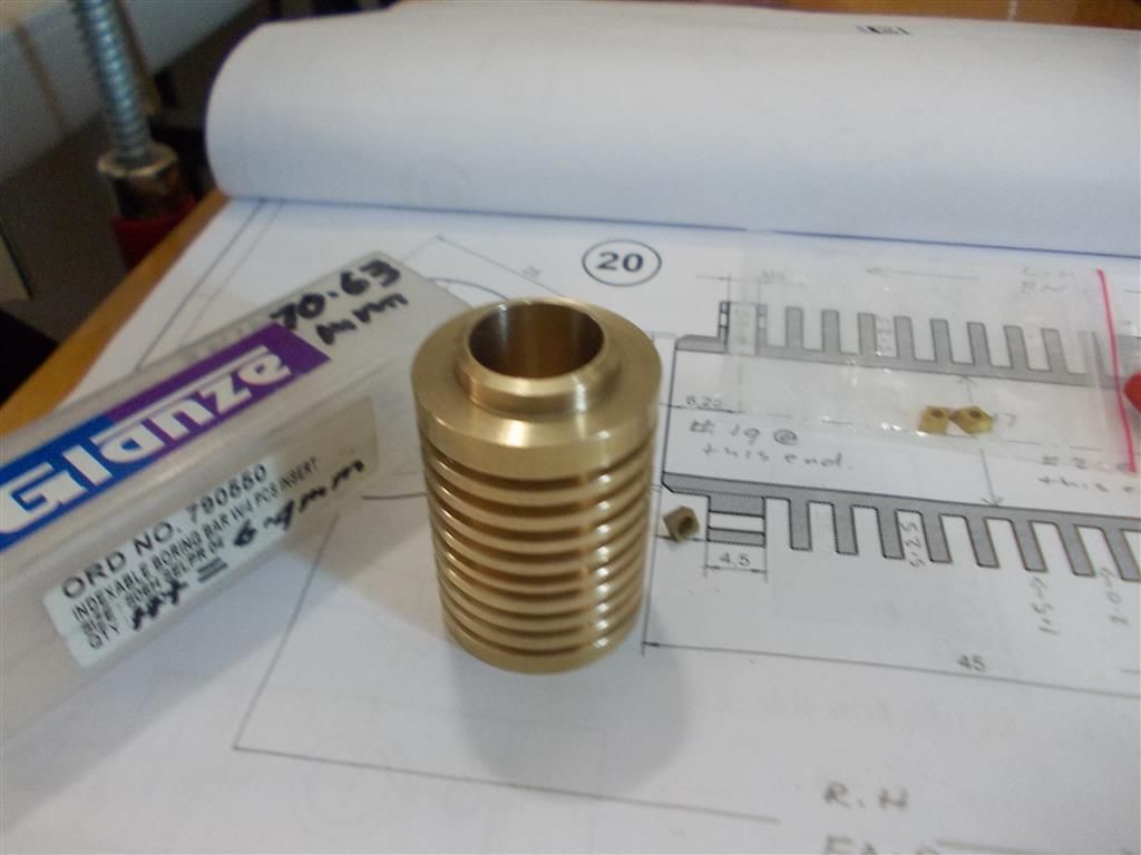
                        The shoulder was machined first, then chamfered. The cooling fins for that half were cut then it was turned around to complete the cooling fins. I then drilled out to 12mm using my very large tailstock chuck (3-16mm) and the stub drills. I started at 4mm and went up in 1.5mm increments. Many thanks to whoever suggested I buy those stub drills. They are extremely useful. I would like some even larger ones now If I can find them ( 13, 14 and 15mm). the boring was completed using the boring bar. I think I may need a larger boring bar in future.

                        So the cylinder is now ready for drilling and tapping tomorrow. It has been bored out to 15.8mm ready for honing. I am still not sure whether to try and make up something myself or buy a brake hone.

                        cylinder 6.jpg

                        cylinder 5.jpg


                        Edited By Brian John on 07/06/2016 10:30:10

                        Edited By Brian John on 07/06/2016 10:33:04

                        Edited By Brian John on 07/06/2016 10:34:16

                        #241820
                        Ian S C
                        Participant
                          @iansc

                          To make the slit, clamp the bush by its ends in the bench vise, and attack it with a hack saw, if you look along the bush you see a line one side a shadow, the other light reflection, cut along that and if its not straight, who cares, it still works. I use these, and also use brass grub screws if I'm clamping down on the bare shaft so it isn't damaged. My motors are used for experimental driving of various bits and pieces, generators, water pump, power hacksaw, and the pulleys are off and on quite often. Ian S C

                          #241826
                          Brian John
                          Participant
                            @brianjohn93961

                            I do like the bush idea but I think that is only suitable for the good flywheel. I am not sure how things would go when drilling the flywheel with the crack in it as I do not know how deep the crack goes. I will give it some thought.

                            Jason : if using three grub screws to even things up, would it be better to have all three screws on one side ? The alternative is two screws on one side and one screw on the other side (all at 120 degrees of course).

                            I think I now understand what has gone wrong. The roller bearings are a bit undersize. I had to do a lot of polishing with 1200 grit to get the crank to fit through them. Then when I ream out the flywheels I get a slightly oversize hole so now we have an oversize hole on a slightly undersize crank….not a good combination. I will remember all this when building the next engine.

                            Edited By Brian John on 07/06/2016 14:28:02

                            #241944
                            Brian John
                            Participant
                              @brianjohn93961

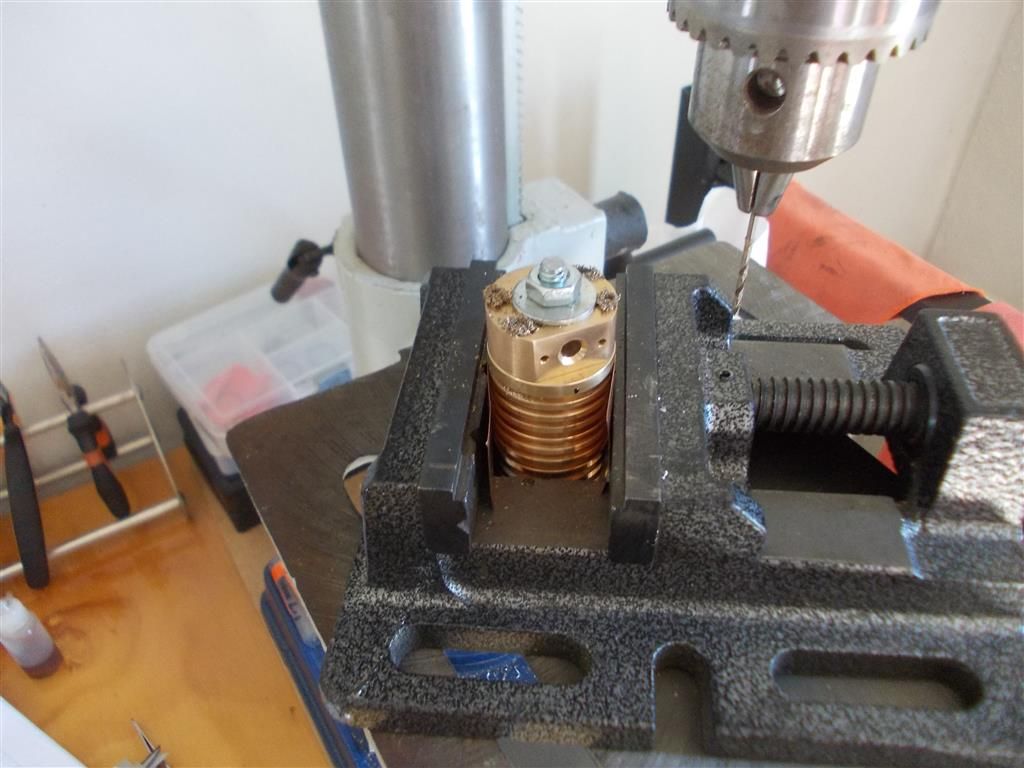
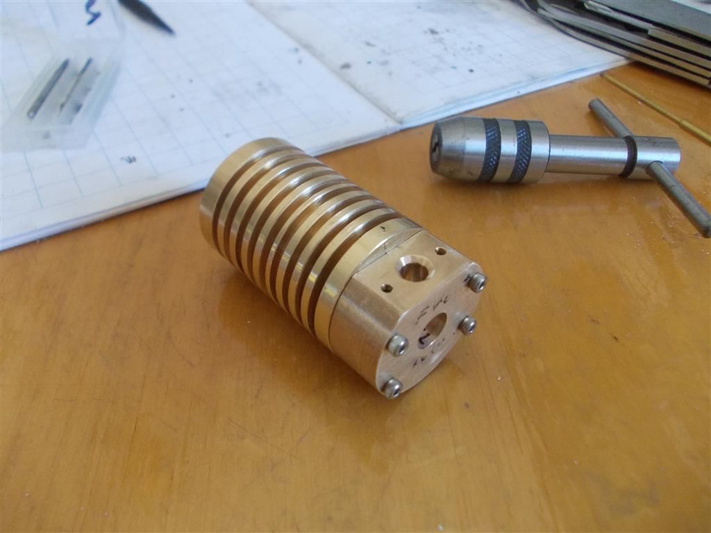
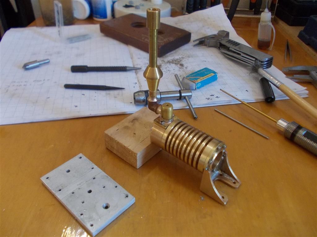
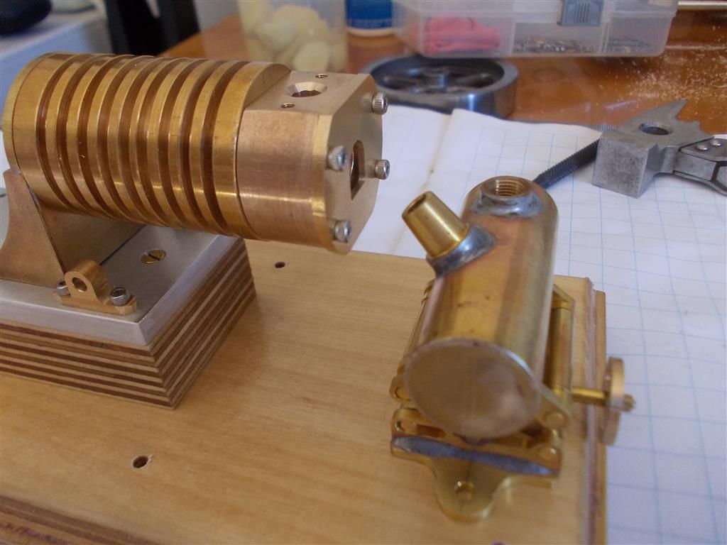
                              Leaving flywheels aside for today, I commenced work on the cylinder assembly. The cylinder head was attached to the cylinder with a large bolt (as per Jason's link) and then the four holes drilled out to 1.6mm using plenty of tap magic. The cylinder head was then removed and the four holes tapped for M2, again lots of tap magic.

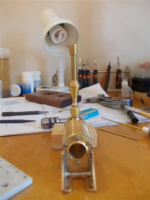
                              The cylinder bracket was fitted and the top hole carefully marked, punched, drilled and tapped for M2. I previously went to a lot of trouble to get my chimney assembly straight so I did not want to muck it all up by getting the cylinder bracket off centre. Once that top centre hole was tapped I could screw the bracket in position then drill and tap for the other holes. All went well and my chimney is nice and straight.

                              At this point I realised that I have not drilled and tapped for the lubricator and I think I should have done that before boring the cylinder. I also need to work out a way to support the cylinder head as I am not happy with the initial design which has everything supported only by the cylinder bracket. It all looks a bit flimsy to me. I have a few ideas in my head but suggestions are welcome.

                              NOTE : I have measured my small drill bits and they seem to be slightly oversize. The 1.7mm are actually 1.75mm and the 1.6mm are 1.65mm. So I am going back to using a 1.6mm tap drill for M2 screws but now I use tap magic for each tap (first , second and third). Hopefully this will be enough to prevent any further broken taps. I now use tap magic when doing anything involving M2 screws and that includes drilling.

                              cylinder 7.jpg

                              cylinder 8.jpg


                              cylinder 10.jpg

                              cylinder 11.jpg

                              Edited By Brian John on 08/06/2016 11:51:19

                              Edited By Brian John on 08/06/2016 12:02:09

                              Edited By Brian John on 08/06/2016 12:03:39

                              #241952
                              JasonB
                              Moderator
                                @jasonb

                                Do the lubricator hole after and the broken cut when boring the cylinder may leave a ridge around the bore as the bit passes the hole.

                                #241960
                                Andy Holdaway
                                Participant
                                  @andyholdaway

                                  Brian, the lubricator on the top of the cylinder is non-functional and purely cosmetic, so you could leave it off if it's going to cause a problem.

                                  #241967
                                  Brian John
                                  Participant
                                    @brianjohn93961

                                    Jason : yes, I agree but I bored out to only 15.8mm so I could go back and take another 0.1mm cut to clean things up after drilling and tapping for the lubricator.

                                    Andrew : yes, I know that it is cosmetic but they also said that the Laura Stirling engine would not need oil and I could not get that to run until after I put a few drops in the cylinder/piston. Of course I can still do that with this engine without having to use the lubricator.

                                    At this stage, I will leave out the lubricator.

                                    I am keen to start honing the cylinder and then making a piston to fit. If I make my own hone from wooden dowel then what grade of paper should I be looking at finishing with : 1500, 2000 or 3000 ?

                                    Edited By Brian John on 08/06/2016 13:22:44

                                    #242064
                                    Brian John
                                    Participant
                                      @brianjohn93961

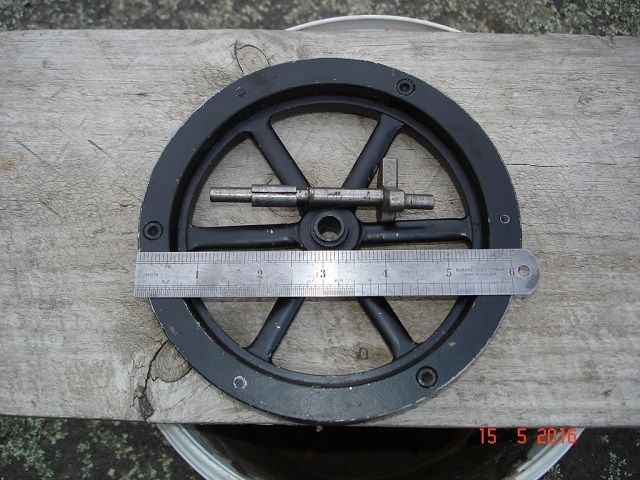
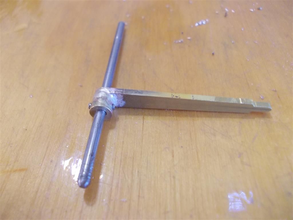
                                      This is a picture of the completed valve gear I have found on the internet. The original plans call for the middle valve gear to be soft soldered to the shaft. The builder here has put a bushing on the valve gear so that adjustments can be made to the angle. I think this is a good idea but the bushing must be soldered to the valve gear. How could this be done ? I was thinking of fluxing the bush and the valve gear then oiling the shaft then sliding it in place. Would the oil stop the solder from sticking to the shaft or is there a better way to do this ?

                                      I had assumed that the two valve gears were at 180 degrees to each other but the plans do not say and many photos show a slight angle.

                                      valve gear bushing.jpg


                                      Edited By Brian John on 09/06/2016 12:17:35

                                      #242070
                                      JasonB
                                      Moderator
                                        @jasonb

                                        Couple of ways to locate the bush on the arm.

                                        1. Make the bush with a spigot to fit the existing hole in the arm and drilled through with a pilot hole, solder to arm (silver) and then open out the hole to finished size which will remove any metal within the original hole.

                                        2. Enlarge hole in arm then make the bush with a spigot to suit the larger hole and drill/ream it to finished size. you can then locate the spigot in te arm and silver solder.

                                        3. Rather than oil the existing shaft use a piece of aluminium which will keep things lined up and if you SOFT solder then it should not stick. Tap the aluminium out of the hole once things have cooled down.

                                        #242172
                                        Brian John
                                        Participant
                                          @brianjohn93961

                                          The first idea seems the best ; I will give that a go later today. I would try the third option but I have no aluminium rod on hand (not sure where to buy it Australia).

                                          Edited By Brian John on 10/06/2016 02:11:04

                                          #242187
                                          Brian John
                                          Participant
                                            @brianjohn93961

                                            I made the bush as per Jason's instructions (1) and that all went well. At a later date when I have ascertained the correct position for the valve then I might soft solder it in position. M2 grub screws are very small and I am not sure how well they hold.

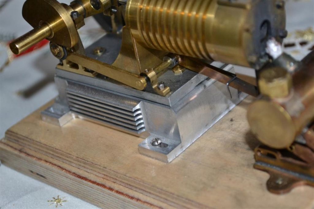
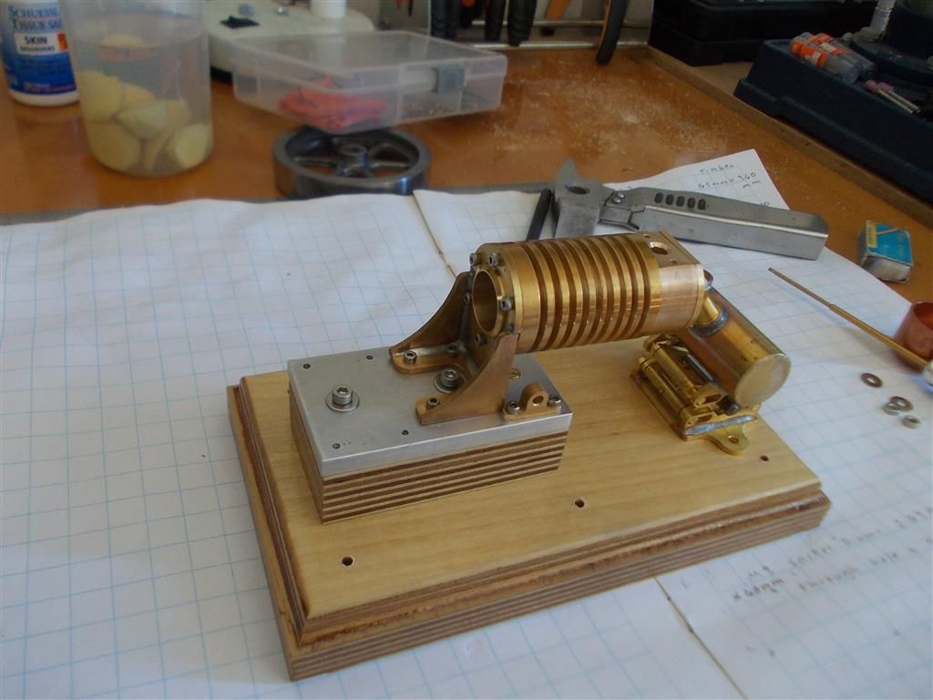
                                            I started to assemble some of the parts to the timber to see how it all fits together and I ran into a few problems. Most photos show the small wooden base to which the aluminium plate is attached, fixed right at the back of the larger wooden base. However, if it is set up like that then the burner will be nowhere near the cylinder. So I have moved the small wooden base further along but still not enough. I think I am going to be about 10mm short. The burner in its current state cannot be moved further in because of the adjustment wheel. I may have to put the burner on a small 3mm thick base to raise it up so that it can be moved closer to the cylinder.

                                            I think the whole vertical adjustment thing is not very useful. Horizontal adjustment would have been better. I will leave it for now to see how it runs when it is all assembled and work out the best position for the burner from there.

                                            NOTE : you can see in the photo I posted yesterday of somebody else's engine that he has built it so that he can adjust the position of the engine in relation to the flame. 

                                            slide valve 1.jpg

                                            assembly 1.jpg

                                            assembly 2.jpg

                                            Edited By Brian John on 10/06/2016 10:33:56

                                            #242319
                                            Brian John
                                            Participant
                                              @brianjohn93961

                                              I have run out of other parts to make so now I will have to look at those flywheels again. I am going to re-drill those holes with a 7.8mm stub drill, then use an 8mm reamer. I will then make a split bush to fit this 8mm hole and the 6mm crank.

                                              Let us assume that the 6mm hole I have already drilled is slightly off centre. Once (if) I get the inner rim of the flywheel running true on the lathe will I be able to bring things back on centre when I re-drill with the 7.8mm stub drill ?

                                              NOTE : I have reordered the cylinder bracket parts (19) and the crank plates (5). I am going to try and silver solder them to see if they distort. The instructions warn against using silver solder for this but I want to see for myself if it can be done. The trick might be to use the bare minimum amount of heat and no more.

                                              Edited By Brian John on 11/06/2016 11:16:32

                                              Edited By Brian John on 11/06/2016 11:17:30

                                              #242330
                                              Michael Gilligan
                                              Participant
                                                @michaelgilligan61133
                                                Posted by Brian John on 11/06/2016 11:16:14:

                                                Let us assume that the 6mm hole I have already drilled is slightly off centre. Once (if) I get the inner rim of the flywheel running true on the lathe will I be able to bring things back on centre when I re-drill with the 7.8mm stub drill ?

                                                .

                                                Almost certainly not, Brian

                                                … This an ideal job for a boring bar.

                                                MichaelG.

                                                #242334
                                                JasonB
                                                Moderator
                                                  @jasonb

                                                  What Michael says, the 7.8mm will just follow the 6mm hole.

                                                  #242335
                                                  Brian John
                                                  Participant
                                                    @brianjohn93961

                                                    Okay, I thought by using a stub drill it might not follow the hole.

                                                    But my boring bar requires a minimum 7mm hole.

                                                    #242336
                                                    JasonB
                                                    Moderator
                                                      @jasonb

                                                      Poke a 7mm drill through and then use the boring bar, I can't imagine the hole will be so far off that the hole won't be concentric by the time you get to 8mm.

                                                    Viewing 25 posts - 101 through 125 (of 246 total)
                                                    • Please log in to reply to this topic. Registering is free and easy using the links on the menu at the top of this page.

                                                    Advert

                                                    Latest Replies

                                                    Home Forums Miscellaneous models Topics

                                                    Viewing 25 topics - 1 through 25 (of 25 total)
                                                    Viewing 25 topics - 1 through 25 (of 25 total)

                                                    View full reply list.

                                                    Advert

                                                    Newsletter Sign-up