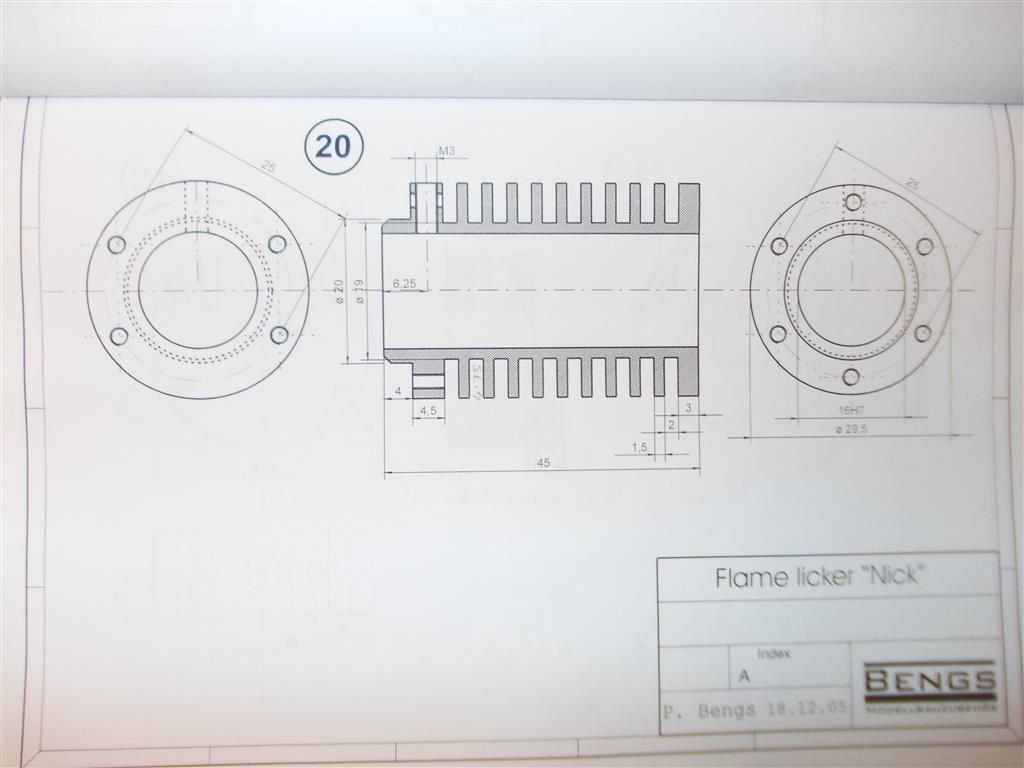
Brian If you look carefully you will see the 19mm is the outside diameter of the cylinder at the depth of the fins It has nothing to do with the chamfer
Jason : that D shape is part 22 (cylinder head cover) and it is pre milled ie. already cut to shape.
Roy : that is what I was trying to say. The 19mm is nothing to do with the chamfer. You said all the dimensions to cut the chamfer appear to be there so I thought you had assumed that the 19mm was part of the chamfer dimension. I still think the chamfer is missing its dimensions but as I am not going to cut it (at this stage) then it does not matter.
Part 22 (photo3) has been pre-made but there are etch markings of some sort on the surface. I think these will have to be removed somehow…..I am not quite sure how I will do that yet.
I finished the burner today. The ends of the tank were silver soldered, the wick holder was soft soldered using 243 degree solder, then the filler plug bushing with 188 degree solder. The base of the scissor frame was soldered using 243 degree then the tank soldered to the scissor frame using 145 degree. It all seems to work rather well. The soldering could have been neater : I am used to free flowing silver solder and the 243 does not flow as easily. The 188 and 145 flow quite readily. I will know next time.
Instead of using some brass tube as a rivet for the scissor frame as per the instructions I have used a 3mm thread cut from a socket cap and held on with M3 nuts. I will put some brass M3 nuts on later after it comes out of the white vinegar pickle.
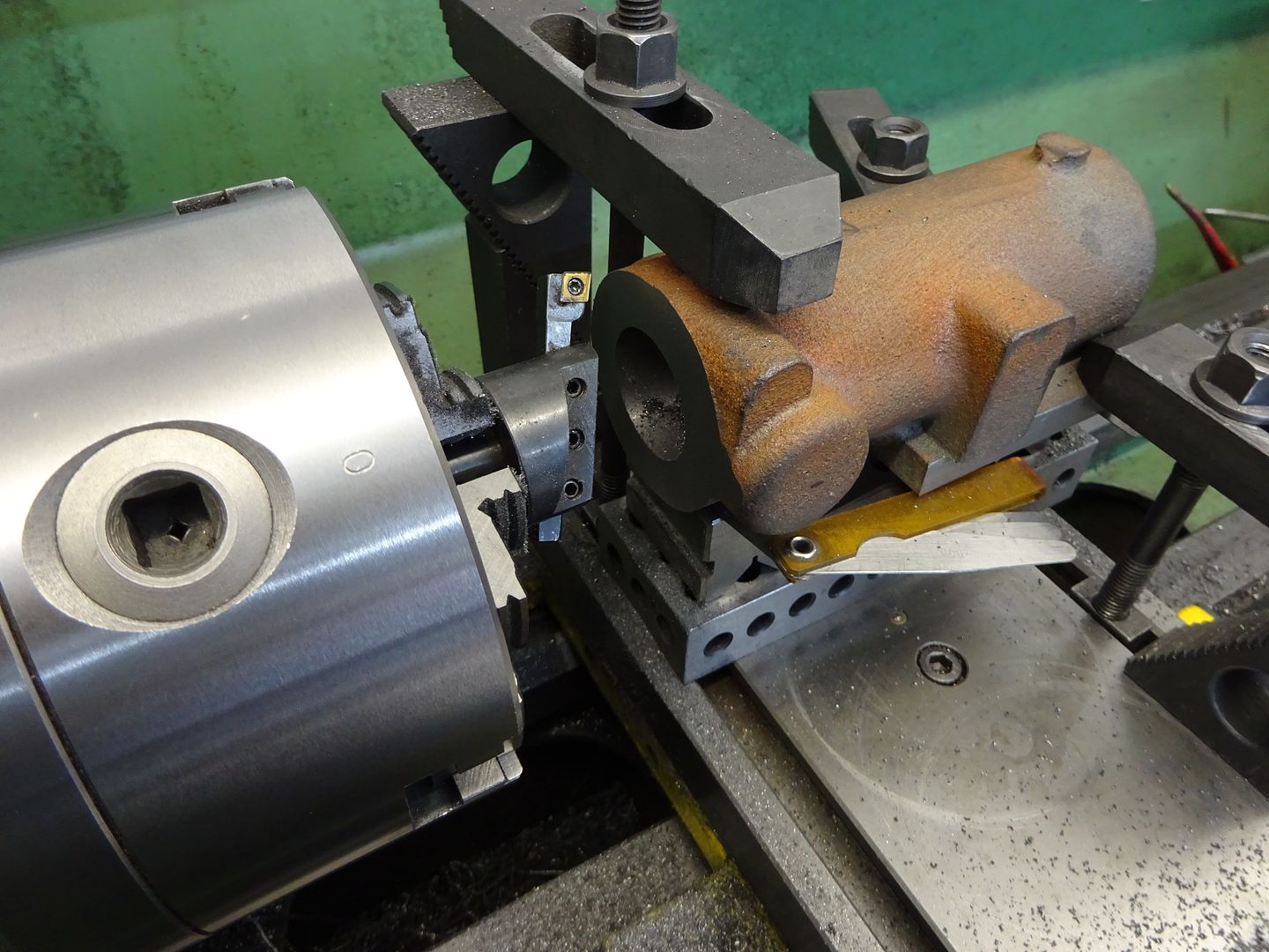
You can also see where I have made a start on parts 20 and 21 by parting off. The instructions say to bore the cylinder first then cut the cooling fins but I am inclined to cut the cooling fins first so that I can support the cylinder between centres.
Those are marks left from when the "D" shape was cut with a CNC mill and are more visual than an actual rough surface, I would not worry about them at the moment.
Yes probably best to drill a ctr hole for teh tailstock to give support while you cut teh grooves and then bore it out.
I can definitely feel those marks with my finger. The instructions say to polish the slider plate (23) and cylinder head (21) with a fine grinding compound to get a perfectly smooth surface. I would have thought that the cylinder head cover (22) should also be polished but I will just leave it for now. Perhaps the slider plate does not rub on that…we will see.
On my flame lickers I lapped the sliding valve plates, mine have the advantage of having a slot that goes right across the head, the head and the valve on my motors are cast iron. If you look in the sticky in the beginners section you might be able to nut out the drawings. Ian S C
I had a few problems making up the cylinder head (part 21) today. I marked an 18mm chord on the work piece then attempted to cut it off with the slitting saw. I wasn't sure if the piece could be held firmly with only one bolt but it was no problem. The slitting saw would only cut half way before the nut got in the way even though I was using a smaller nut than that supplied with the saw. So I had to turn it over to complete the cut. The cuts did not meet so I evened things up with the bench grinder then I used a large file while the piece was held in a vice. By the time I got a perfect rectangle on top I was down too far and the chord was actually 21mm.
So I fished around in my box of parts and found two 30mm diameter brass cylinders which were 12.5mm thick, both with a 6mm hole already drilled…sometimes you get lucky ! I faced off until they were both the required 12mm thick and bored out the centre holes to 8mm. I used the slitting saw to cut a 15mm chord (not 18mm), then the bench grinder, then the big file while held in the vice and finished off with 800 grit on a sheet of glass. This time I ended up with the correct dimensions and a perfectly flat surface on which to mount the exhaust chimney. Yes, I made two of them ! I still have to tap and drill them tomorrow ; extra care needed here.
If you look at the plans above you will see that they mark the countersunk hole as 7X90 degrees. Where do they get 90 degrees from ? All the countersunk holes are marked like that.
Grinding brass clogs up the wheel face, and later grinding will tend to make the wheel heat up, this can in extreme cases cause the wheel to crack. the wheel needs dressing to clear the brass, there is probably not much there. Just another degree on the learning curve. Keeping a few files for brass only work is a good idea, for small jobs filing is often quicker than setting up and machining. Ian S C
You can use the same method that you used when sawing. But it would be better if your topslide could be removed and the work held to that but not sure if yours can?
I have finished drilling and tapping the cylinder head and it can be seen with the chimney attached in photo 1.
I did some more soft soldering today ; the 188 degree solder seems to flow more readily than the 243 degree solder so I am using that. The eccentric and its bushing did not give any problems but the crankshaft did as I suspected it would. The problem is getting enough flux in the right place. You have to flux before you put the parts together and moving the crank plates along the crank shaft removes most of the flux.
I decided to drill and tap the crank plates for M2x3mm grub screws to hold everything in place before soldering. I can file the grub screws off later if they have been soldered into position. I got the job done but it does not look very neat ; I could not get the solder to flow properly because of the lack of flux. Removing the grub screws shows that enough solder got through but I am not happy with the result. How should I have done this ?
Another way would be to not use solder at all and just drill and tap right though to the crank (M3X4mm grub screw) then Loctite everything into position. I might order these parts again and give that a go at a later date.
NOTE : that is my new hand held burner for soft soldering.
To dress the wheels on my grinder I use a star dressing wheel, you may know these things, a steel/cast iron handle, with alternately placed plain and star shaped washers that are run against the rotating grinder wheel, also useful if you manage to wear a groove in the face of the grinder wheel. There are other types of dressers usually with one or more diamonds in the end, they aren't that expensive, but although you don't need one often, you really do need some way to dress the grinder. The crankshaft could be assembled with shaft lock Loctite, I'v done that on my smallest motor with 3 mm diameter shaft and crankpin and the crank cheeks are about 2 mm thick, it hasn't fallen apart ——yet. Ian S C Sorry I thought the crankshaft was more visable
I have ordered a diamond tip dresser ; that will do for a start.
I have a bigger problem now : I have carefully drilled and tapped all 12 holes in the aluminium base plate only to discover that the socket caps will barely engage the threads…how frustrating. Some weeks ago I switched from using 1.6mm to 1.7mm tap drills for 2 X 0.4mm threads after experiencing two broken taps. This has worked well for brass but I think aluminium requires 1.6mm. I will have to drill and tap it all again.
I was going to make a start on the cylinder today but there is still one confusing part in the instructions :
''An M2 screw must be adjusted to fit the top M2 bore hole on the cylinder bracket side.''
I assume they are referring to the M2 screw which passes through the lubricator hole. Note that six holes must be drilled and tapped on the LH side of the cylinder in the diagram below. What do they mean by ''adjusted'' ? I am thinking of rotating the cylinder 30 degrees so that no screws pass through the lubricator hole. But this would leave the lubricator tilted at 30 degrees to the vertical and it might look a bit funny.
That would mean it only goes in 0.75mm. It is hardly doing much at that length is it ? What about my idea of rotating the cylinder 30 degrees.
NOTE : it specifically mentions not using any oil on the piston so I wonder if a lubricator is necessary at all.
I could also skip out that first cooling fin and move the lubricator further along. That would give an extra 1.75mm of thread. But probably best to leave that option for now.
Brian, I used to dress my wheels with a diamond dresser [we used them all the time in the decorative glass trade] dressing all the processing wheels, but now all I do is buy a cheap diamond angle grinder wheel [sometimes for a quid at autojumbles & steam rallys] & offer it horizontally to the grinder & it cleans it up a treat, & it's so cheap.