Has anybody built Beng’s Danni Steam engine.

Advert

Has anybody built Beng’s Danni Steam engine.

Home Forums Stationary engines Has anybody built Beng’s Danni Steam engine.

Viewing 25 posts - 76 through 100 (of 304 total)
  • Author
    Posts
  • #258293
    Neil Wyatt
    Moderator
      @neilwyatt
      Posted by Brian John on 27/09/2016 07:59:52:

      I am not sure how to calculate E because I do not know what the valve travel is.

      Always twice the eccentricity of the eccentric – think about it, if the hole is offset 3mm at the two extremes it will bee 3mm closer and 3mm further from the centreline, a total of 6mm, passed on to the valve.

      Neil

      Advert
      #258400
      Brian John
      Participant
        @brianjohn93961

        Did anybody try the Tubal Cain formula ? I am not getting 4.4mm.

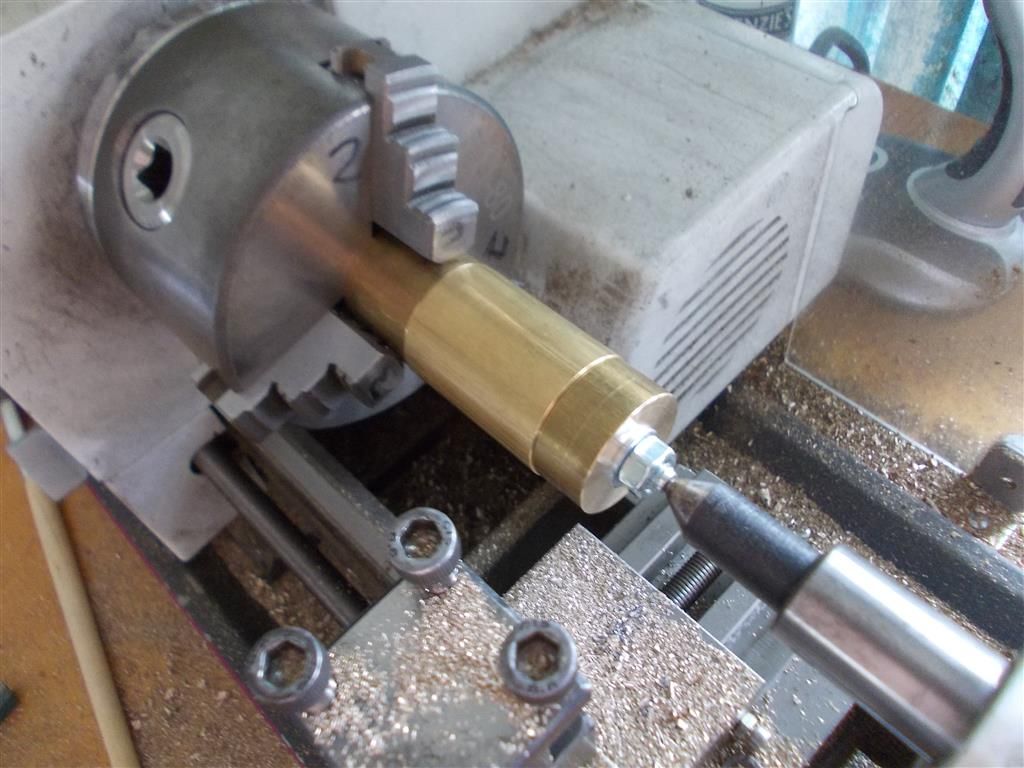
        I have made two jigs to support the cylinders while I turn the outer contour. I will do that tomorrow as I ran out of time today. What tool should be used to do this ? I used a centre drill to drill a small hole in the end of the M6X75mm set screw so that it can be supported between centres.

        I still have not decided how to make the flat on the cylinder : I am considering all options. I do not think the 4 jaw chuck would be successful. Like it or not, I may have to wait for the vertical milling slides to arrive in Australia in December. The other way is to remove the top slide then bolt the cylinder to the tool post and use a fly cutter in the lathe chuck.

        cylinder 6.jpg

        cylinder 7.jpg

        Edited By Brian John on 29/09/2016 07:59:44

        Edited By Brian John on 29/09/2016 08:01:34

        Edited By Brian John on 29/09/2016 08:08:15

        #258401
        JasonB
        Moderator
          @jasonb

          Parting tool, make a series of overlapping plunge cuts almost to depth and then finish by taking very shallow 0.1mm cuts and running the tool along the work. Just think of it like one of the eccentrics but longer.

          #258424
          Hopper
          Participant
            @hopper
            Posted by Neil Wyatt on 28/09/2016 12:24:59:

            Posted by Hopper on 27/09/2016 01:55:35:

            That last 3 should be a small superscript 3 as it indicates "cubed" rather than " x3" but I can't do it right. "–" signifies "minus", I just cant do long dash on this system.

            On a computer you can use x^2 or x^3 to show squared and cubed.

            a simple – for minus is best as — has a special meaning in some computer languages so you might create some confused nerds

            Neil

            Thank you Neil. I learn something new every day on this site!

            #258425
            Hopper
            Participant
              @hopper
              Posted by Brian John on 28/09/2016 08:24:34:

              Maybe, but I am not sure the grub screw would have had enough ''grip'' on the shaft. I will remember that next time and give it a try.

              You could also Loctite the piece on to the shaft instead of using a grub screw. Just heat the parts up with your propane torch when finished until the Loctite gives way. (Obviously, dont use hi temp Loctite!)

              #258426
              Hopper
              Participant
                @hopper

                Brian, you know how it is waiting for stuff to arrive in Australia. I would seriously look at setting a flycutter to the exact height of the flat you want to machine then bolt the job to the cross slide with appropriate packing. You might make a dummy piece for your first trial. You could machine a number of flats on that and prove your method before attacking the real part.

                #258431
                JasonB
                Moderator
                  @jasonb
                  Posted by Brian John on 28/09/2016 08:24:34:

                  Maybe, but I am not sure the grub screw would have had enough ''grip'' on the shaft. I will remember that next time and give it a try.

                  Can't see why your M3 grub screw won't grip as well as the one in my photo which also has a shorter thread length and was cutting a lot more steel away rather than a light skim cut off your smaller dia brass eccentrics.

                  #258551
                  Brian John
                  Participant
                    @brianjohn93961

                    I used the parting tool from the Arc Euro cutting tool set to do it : this parting tool is too thick to use as a parting tool on my lathe but it worked perfectly for this. I put some back rake on it with the bench grinder. I was able to take a 0.1mm cut then just move it down the length of the cylinder until I got to the other end. I did this ten times at that was it.

                    I have ordered a 14.5mm  fly cutter to cut the flat…I may as well give it a go.

                    http://www.ebay.com.au/itm/291799221718?_trksid=p2060353.m1438.l2649&var=590809882369&ssPageName=STRK%3AMEBIDX%3AIT

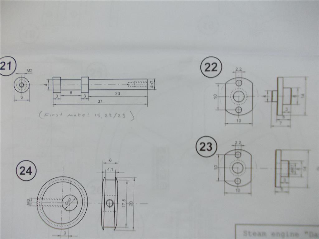
                    I am thinking of making the control valve (part 21) next but it is supposed to be made from 6mm diameter stainless steel. There are two problems with that : there is an M2 thread to cut in the end and the rod must be a nice smooth finish to pass through a 4H7 hole. I think I would struggle to get a good finish on either stainless or silver steel on my lathe and as for drilling and tapping the M2 hole… I know how that would end !

                    Could I make the whole thing from gunmetal bronze ?

                    control valve 1.jpg

                    cylinder 8.jpg

                    Edited By Brian John on 30/09/2016 10:35:35

                    #258557
                    Hopper
                    Participant
                      @hopper

                      Mild steel might work better.

                      #258560
                      Brian John
                      Participant
                        @brianjohn93961

                        I am really not keen on drilling and tapping into any type of steel : that is just asking for a broken tap in a blind hole. M3 would be okay but M2 taps are not exactly robust.

                        #258566
                        JasonB
                        Moderator
                          @jasonb

                          Bronze should be OK and will run alright in the brass. At a push you could get away with a high temp loctite to stick a couple of "rings" onto a 4mm rod.

                          What goes into the tapped hole? again a plain 2mm hole and you could loctite in a 2mm rod that has had the other end threaded M2. Or just use a longer bit of material, turn the end down to 2mm dia and thread for the nut

                          Edited By JasonB on 30/09/2016 11:38:19

                          #258567
                          Brian John
                          Participant
                            @brianjohn93961

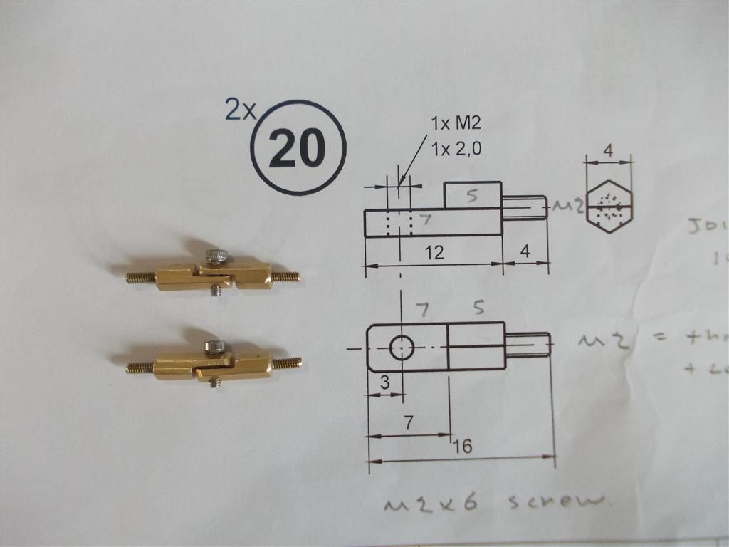
                            Part #20 (joint part) connects to the control valve.

                            joint part (20).jpg


                            Edited By Brian John on 30/09/2016 11:43:28

                            #258568
                            JasonB
                            Moderator
                              @jasonb

                              If you could get those treaded spigots out (heat to weaken locktite) then you could use a longer bit of material, reduce end to 2mm and thread then part 20 can screw onto that.

                              #258570
                              Brian John
                              Participant
                                @brianjohn93961

                                Yes, I could try that. I will also try making it out of gunmetal and see how that goes. What about using a 1.7mm tap drill into steel instead of the usual 1.6mm tap drill ? That might lessen the chances of a broken tap although I am still not keen. I have to make at least two of these control valves so I might try a few different methods.

                                I think I could even do away with half of part 20 and join the control valve directly to the remaining half by making the rod longer and grinding a flat on the end. A hole could be drilled in the flat and a nut used to hold the screw.

                                Edited By Brian John on 30/09/2016 12:09:13

                                #258572
                                JasonB
                                Moderator
                                  @jasonb

                                  Yes 1.7 should be OK. If you drill and tap the hole as the first operation you won't have wasted a lot of machining time if things go wrong.

                                  #258982
                                  Brian John
                                  Participant
                                    @brianjohn93961

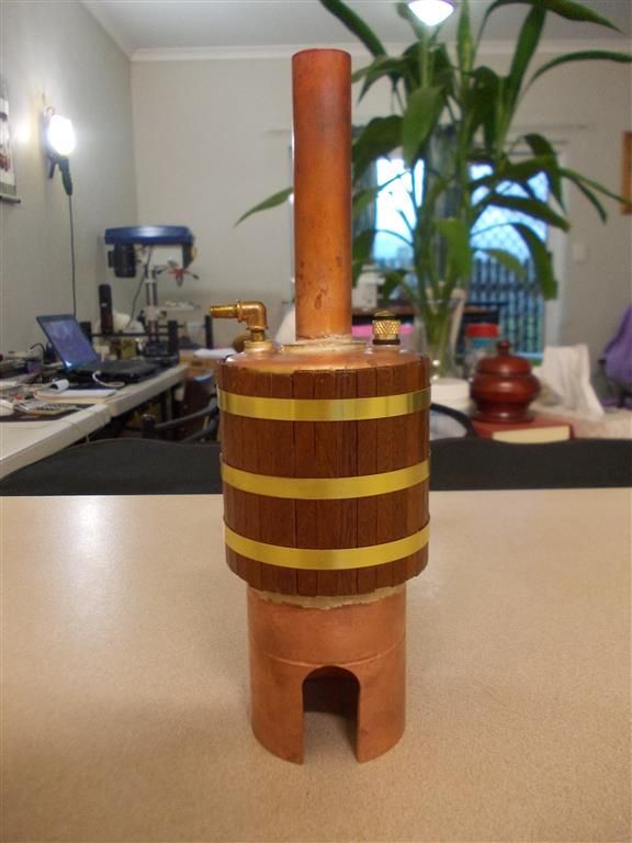
                                    We had a power failure in this area this afternoon so I was without a lathe for most of the day. I finished putting the mahogany timber lagging and the boiler bands on the boiler instead. There is no real need to do this but it does look much better and makes it a easier to pick up when it is hot….it looks quite smart too !

                                    boiler 2.jpg


                                    Edited By Brian John on 03/10/2016 11:27:53

                                    Edited By Brian John on 03/10/2016 12:09:39

                                    #259459
                                    Brian John
                                    Participant
                                      @brianjohn93961

                                      1. It does not look like they have used any solder on the steam chest cover here although the instructions say to soft solder it. Could I get away with using Hylomar ?

                                      **LINK**

                                      2. Making the crank shaft : I am having eight of the crank arms (part #7) sent out to me so I can have another go at making the crank shafts. I did manage to make a crank shaft for the flame eater engine without any problems but perhaps that was a fluke. How can I get the holes in the crank arms parallel so that the shafts end up parallel to each other ? I intend to Loctite two of them together and then drill the pair both at the same time. Is there another way to do it ?

                                      NOTE : The crank arms are pre-drilled to 5.8mm and I use the 6H7 reamer to enlarge the holes I have been lining up the top edge of the crank arm with the top of my drill press vice but this is not getting a satisfactory result.

                                      Edited By Brian John on 06/10/2016 10:30:04

                                      #259486
                                      JasonB
                                      Moderator
                                        @jasonb

                                        Cover just needs sealant.

                                        Try clamping the crank arms down to a flat plate with a slightly larger hole under the one being reamed. It is likely that as you are tightening teh jaws of your drill vice the moving one is lifting up slightly and tilting the work.

                                        #259521
                                        Brian John
                                        Participant
                                          @brianjohn93961

                                          Would a better quality vice help ? I have been looking at this one for a while now :

                                          **LINK**

                                          #259523
                                          JasonB
                                          Moderator
                                            @jasonb

                                            Generally a machine vice is built a bit better than a drill vice so should have less jaw lift but like every thing you get what you pay for and you can pay £1000 for a "precision" vice. The work "precision " in this case is used to describe the style of vice and may or maynot describe the quality.

                                            Have a search on Google images for "engineers finger plate" thats the sort of thing but they can easily be knocked up from a couple of scraps and a screw

                                            #259550
                                            Neil Wyatt
                                            Moderator
                                              @neilwyatt
                                              Posted by Brian John on 06/10/2016 14:37:29:

                                              Would a better quality vice help ? I have been looking at this one for a while now :

                                              **LINK**

                                              I have a similar one. The actual keep plate is about the same size as that of a drill vice so the improvement in gripping comes from it all being more accurately made with better proportioned adjusting screws. Mine is a lot better than a drill vice but as Jason says 'YMMV'.

                                              Neil

                                              #260241
                                              Brian John
                                              Participant
                                                @brianjohn93961

                                                I am still waiting for the fly cutter to arrive so I have not cut the flat on the cylinder yet. I have made four cylinder covers but I have not yet drilled and tapped the cylinders. I will wait and see if I stuff things up with the fly cutter…I am not very confident about it !

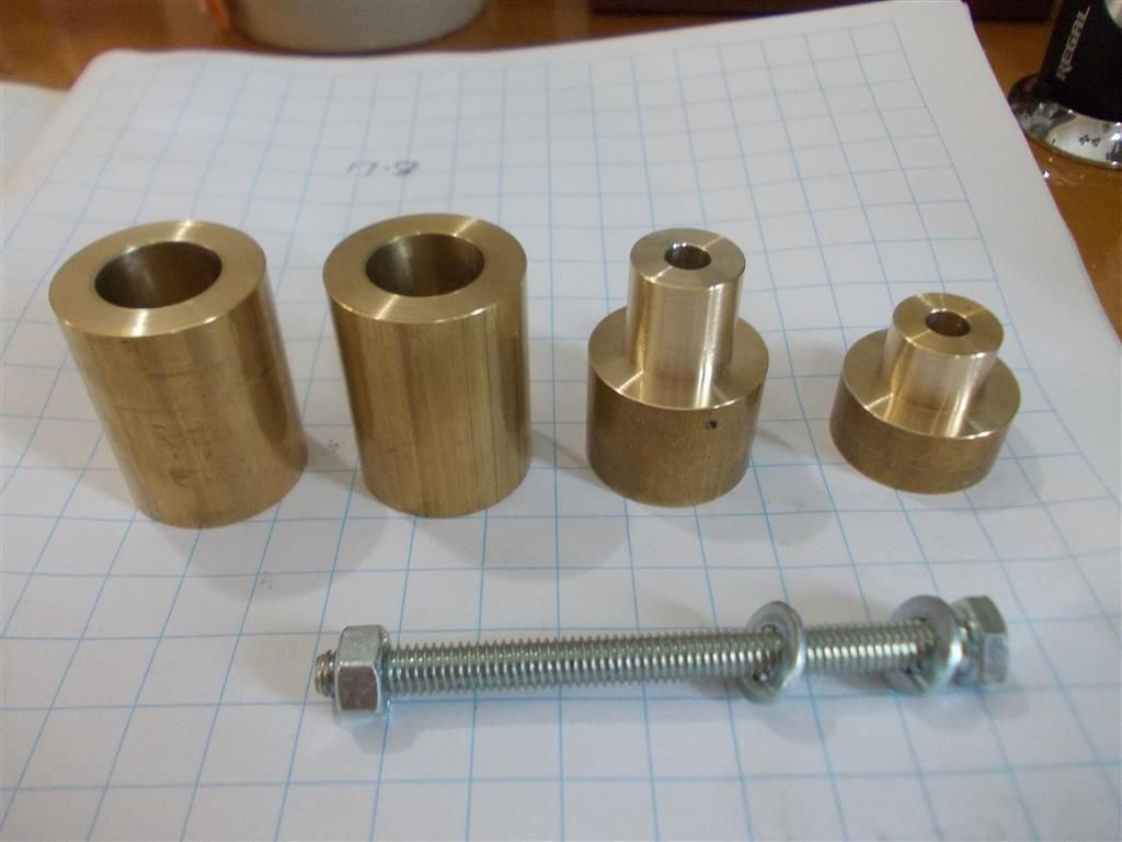
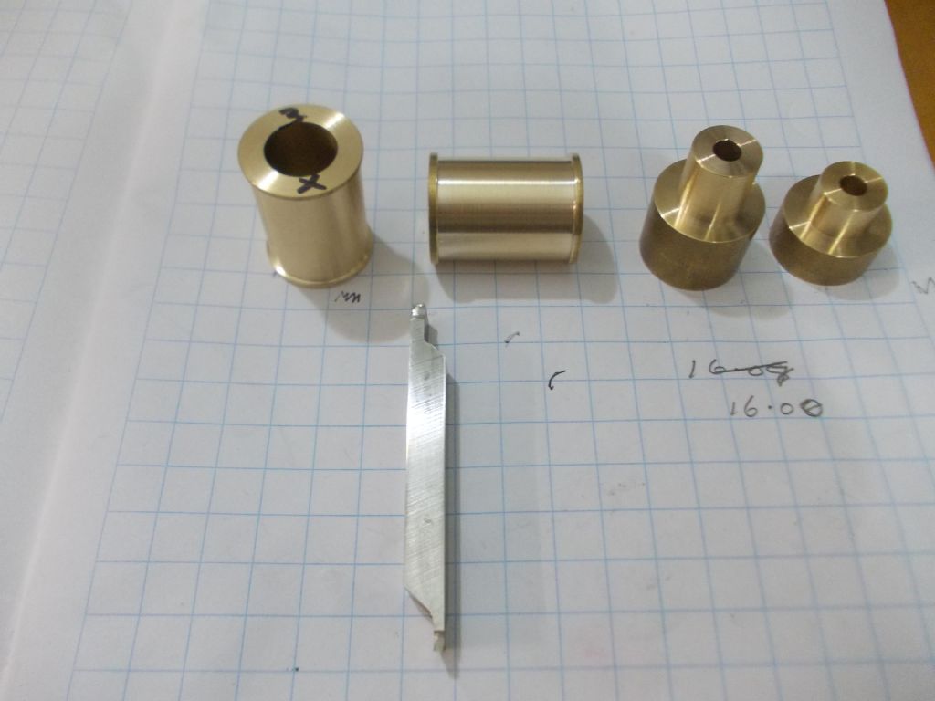
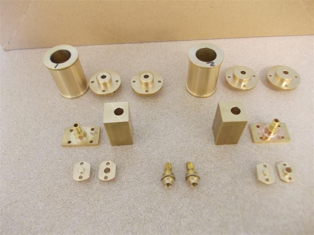
                                                I made the steam covers today (parts 22 and 23 – front row of photo) : very fiddly little things. Grinding the flats on each side was a real pain. I used a stone in the Dremel tool ; you only get about 20 seconds of grinding before the brass part gets too hot to hold. I tried using thick riggers gloves for my hands but the part was too small to get a good grip. How would you have done this ?

                                                I have also made  threaded bushings (3/16-40) for the steam chest covers (part 18 – middle row) and silver soldered these in place. The instructions say to soft solder it  but this will make things easier after the steam chest has been soft soldered to the cylinder with solder paste. I have also made threaded bushings (middle of the front row) to be silver soldered to the top of the steam chest although the hole there is 7mm deep so I may be able to drill and tap for a 3/16-40 pipe nipple…I am still thinking about that.

                                                Tomorrow I will finish the steam chests. I have only drilled and reamed the 6H7 holes so that I could make the steam covers.

                                                steam covers 1.jpg


                                                Edited By Brian John on 10/10/2016 08:10:55

                                                #260244
                                                roy entwistle
                                                Participant
                                                  @royentwistle24699

                                                  Brian Do not grind brass It clogs the wheels

                                                  Roy

                                                  #260261
                                                  Ian S C
                                                  Participant
                                                    @iansc

                                                    Use a nice new file on brass, and keep the file for brass only, use older files for steel.

                                                    Ian S C

                                                    #260263
                                                    Brian John
                                                    Participant
                                                      @brianjohn93961

                                                      Then how are those ''edges'' to be removed ? I was going to use a slitting saw but the items are far too small and cannot be held in the tool post.

                                                      NOTE : Dremel stone wheels are cheap and can be discarded once clogged.

                                                      Ian : we posted at the same time ! You mean hold it in one hand while filing with the other ?

                                                      Edited By Brian John on 10/10/2016 10:31:55

                                                    Viewing 25 posts - 76 through 100 (of 304 total)
                                                    • Please log in to reply to this topic. Registering is free and easy using the links on the menu at the top of this page.

                                                    Advert

                                                    Latest Replies

                                                    Home Forums Stationary engines Topics

                                                    Viewing 25 topics - 1 through 25 (of 25 total)
                                                    Viewing 25 topics - 1 through 25 (of 25 total)

                                                    View full reply list.

                                                    Advert

                                                    Newsletter Sign-up