Has anybody built Beng’s Danni Steam engine.

Advert

Has anybody built Beng’s Danni Steam engine.

Home Forums Stationary engines Has anybody built Beng’s Danni Steam engine.

Viewing 25 posts - 226 through 250 (of 304 total)
  • Author
    Posts
  • #312877
    Weary
    Participant
      @weary

      The 5mm packing could be placed on top of the wood base-block between the engine frame and the wood? It would then look like part of a cast base if painted, and, if you prefer to leave the metals unpainted look quite attractive as a colour/texture contrast to the brass frame?

      Just a suggestion ….. p'raps pose the bits together as above to see if you like the look?

      (great work btw!!)

      Regards,

      Phil

      Advert
      #312896
      JasonB
      Moderator
        @jasonb

        My thoughts were to pack it up with anything for now so you can test run it and then sort out a better base when you come to do final assembly and paint.

        Though with the old holes filled in and painted the same colour of the engine frame the Ali plate would not look too out of place.

        #312906
        Brian John
        Participant
          @brianjohn93961

          I had intended to place that Al. plate under the small block of wood so that the existing holes would not be visible. I have plenty more Al. that I can cut to that size so a new plate could be made to fit on top of the small block and under the engine frame as suggested. At this point , I am not sure which would look better.

          Bunnings have some Tasmanian Oak which is 25mm thick so I could also cut and varnish another block of timber. It would probably look better than the block of plywood supplied with the kit.

          Lawrie : machining cast iron on my small machine is a real pain. I do not get a good finish so I have to spend a long time polishing it up using 120 to 1500 grit wet and dry. It is far easier to raise the engine a few mm. This is why I prefer brass flywheels ; I get a good finish with little polishing necessary.

          Do you intend to add timber lagging to the cylinders at some point ? I have found that looks quite good. I use JB WELD to glue the timber strips in position. The strips are varnished first on both sides with three coats of matt clear.

          Edited By Brian John on 19/08/2017 17:50:47

          #312921
          Weary
          Participant
            @weary

            You were asking about valve setting (posting timed 12:28:21 above).

            Look at this video from 8:21 onward. The constructor appears to be setting the cylinder at back dead centre and the valve eccentric with the longest axis vertical by eye. Basically, as seen there, the valve is set for equal travel each side the steam and exhaust ports.

            You could set it far more accurately than he has done by using careful measurement to find bdc/fdc accurately and then by observation and measurement setting the valve accurately. I see that the eccentric grub is hidden by the straps when the engine is completed which will make eccentric adjustment more tedious than it need be, however simple eccentric setting with a set square with engine on bdc &/or fdc may be adequate. If necessary/desirable you could use calipers or some similar device and a set square to set the eccentrics still more accurately once bdc/fdc is found.

            Regards,

            Phil

            Edited By Weary on 19/08/2017 19:32:36

            #312962
            Brian John
            Participant
              @brianjohn93961

              Weary : thank you for that video. I may as well start with that ; it looks good. Yes, adjusting the eccentric will be a nuisance due to the hidden grub screw. I realised that yesterday when I was putting the engine together for the first time.

              I just had a disconcerting thought : what if the problem is not the rear control valve spigot but the bore for the control valve is off centre by a few degrees ? I think the PM RESEARCH engines use a Teflon packing arrangement in this area. I have sold those engines so I cannot have a look at it now but that is something to consider if all else fails.

              Edited By Brian John on 20/08/2017 00:59:27

              #313111
              Brian John
              Participant
                @brianjohn93961

                I have re-read the instructions concerning the control valve cover and watched that instructional video again : I had the cover on the wrong way ! The spigot goes inside the steam chest not outside as I had it positioned. Thinking I had solved the problem, I then tried it in the new position…just the same. I also tried the other steam chest and the other cover…just the same.

                I am really not sure what is going on here now. There is nothing else to do but make a new control valve cover and see what happens. The engine is 98% complete but unless I can get this part to fit properly then it will not run.

                #313120
                Brian John
                Participant
                  @brianjohn93961

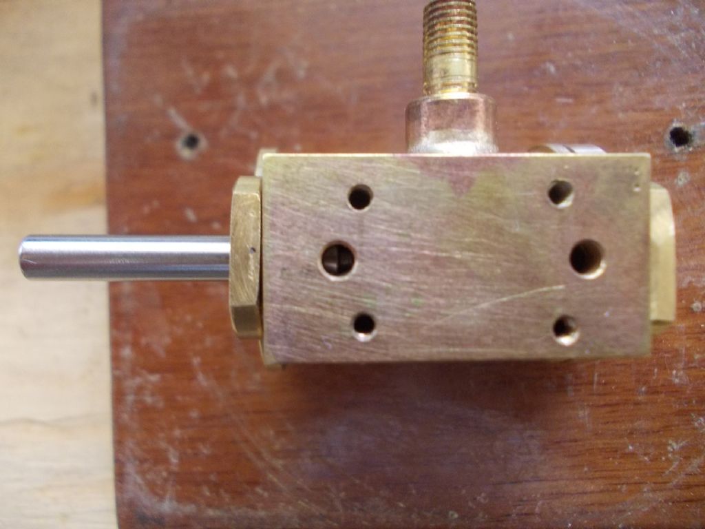
                  I have removed the steam chest cover to observe the operation of the control valve as it moves back and forwards. When it is in the forward position should the steam hole on the right be open or closed ? And when it is in the rear position should the steam hole on the left be open or closed ?

                  I have measured the hole positions and the control valve but something is not quite right. I may have to desolder the steam chest and start again.

                  assembly 4.jpg


                  Edited By Brian John on 21/08/2017 08:07:25

                  Edited By Brian John on 21/08/2017 08:08:44

                  #313127
                  JasonB
                  Moderator
                    @jasonb

                    What the picture does illustrate is that something is out of line as can be seen by the tapering gap where the valve rod cover is against the chest. May be worth measuring where the hole is on either end of the chest as if that is out of line it would cause what we can see.


                    Piston valve positions


                    Edited By JasonB on 21/08/2017 08:49:45

                    #313144
                    Brian John
                    Participant
                      @brianjohn93961

                      Jason : it was not screwed down when I took the photo hence that gap. I have measured all the holes and they are in the correct positions. The control valve is also the correct dimensions so I am not sure what the problem is. The front hole is being fully covered and the rear hole is being partially covered so something is wrong. I think I need to desolder the steam chest from the cylinder. The remelt temperature of the solder paste is about 340 degrees so it should not be too difficult. I do not know what sort of a mess I will be left with once the two pieces are pulled apart.

                      Lawrie : what is happening with your control valves and the steam holes ?

                      NOTE : I thought this engine build would be on par with the their Stirling engine kit !

                      #313150
                      JasonB
                      Moderator
                        @jasonb

                        Brian, how are you measuring the holes each end, it only needs the drill to have wandered a bit to throw things off line maybe 0.2mm or 0.3mm difference.

                        Even if not tightened down it will find its own position so should be sitting parallel to the end of the valve chest

                        #313152
                        JasonB
                        Moderator
                          @jasonb

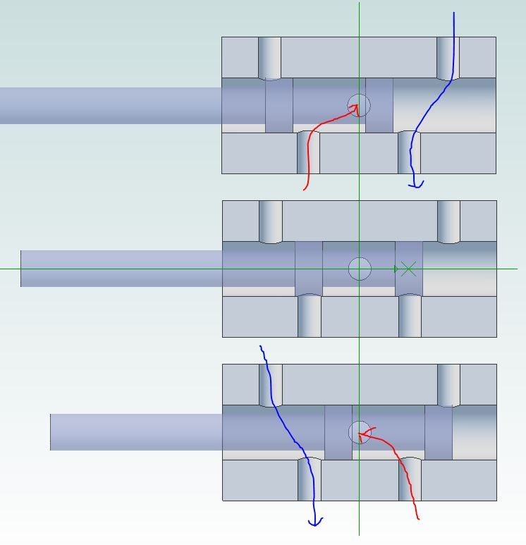
                          Brian, I think your eccentric has 3mm offset so that will move the valve 6mm total, below shows it 3mm to the left, middle and 3mm to the right total 6mm movement, have left out some of the passages for clarity.


                          danni valve.jpg

                          Edited By JasonB on 21/08/2017 10:53:31

                          #313153
                          Lawrie Bradly
                          Participant
                            @lawriebradly72996

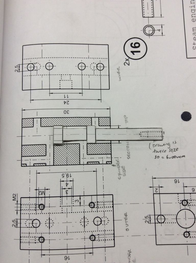
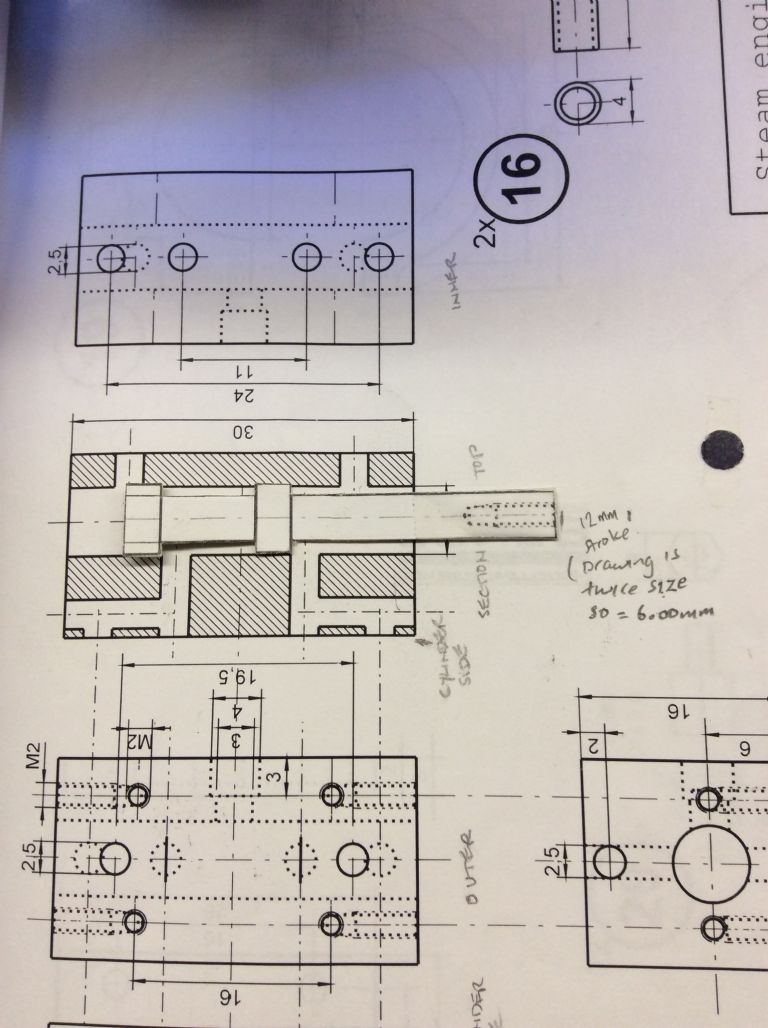
                            img_8167.jpgimg_8168.jpg

                            #313156
                            Lawrie Bradly
                            Participant
                              @lawriebradly72996

                              Hi Brian, While I was messing about taking photos of the drawings, Jason has much more elegantly provided the same message the photos were meant to convey. Like you, I couldn't work out the travel of the valve until a bloke at the local steam railway club suggested I photocopy the drawing of the valve and make a cardboard copy of it, to superimpose on the drawing of the steam chest. I thought it was a very clever Idea. It cleared up the mystery for me.

                              #313404
                              Brian John
                              Participant
                                @brianjohn93961

                                I made another control valve cover today but I still have the same problem. It could mean the bore for the control valve is not perpendicular to the end of the steam chest. That could be due to the quality of the drill press or the ineptitude of the operator….or both !

                                What to do next ? I think I will have to use the Teflon packing arrangement that PM Research use on their engines. That should allow for a bit of error. I can't quite remember how they did it but I will look closely at online photos.

                                You can see the parts 29, 4 , 30 and 18 in the exploded diagram below. They use this arrangement for the piston rod but I should be able to use something similar for my control valve.

                                http://www.jeff-z.com/livesteam/pm-3/pm-3.html


                                Edited By Brian John on 22/08/2017 14:38:33

                                #313696
                                Brian John
                                Participant
                                  @brianjohn93961

                                  I am all astonished : it works !

                                  https://www.youtube.com/watch?v=LD8_fxIZhxE

                                  I made two more control valves using some 6mm bronze bushes fixed to a 4mm steel rod. You can see the old steel control valve beside a new one in the video. I used CHEMTOOLS 8609 retaining compound. It should stand a constant temperature of 150 degrees Celsius. How hot does the steam chest get ? At least I know that the steam chest/cylinder assembly is correct and I do not have to remake that. I can now have another go at making an all steel control valve in case the retaining compound fails.

                                  http://www.chemtools.com.au/product/adhesives-threadlockers/retaining-compounds/general-purpose-2/

                                  I still have to fit the larger cast iron flywheel by raising the engine mounting block by 5mm. I quite like the smaller brass flywheel though. Some screwed parts must be fixed in place with low strength Loctite as per the instructions. The engine runs very well first time ; it self starts as long as it is not on BDC.

                                  NOTE : that 8609 retaining compound grabs in less than 5 seconds so be warned. Forget about the 10 minute fixture time as per the website !


                                  Edited By JasonB on 24/08/2017 08:59:36

                                  #313701
                                  JasonB
                                  Moderator
                                    @jasonb

                                    Looks good Brian running nice and smoothly, maybe something was not quite concentric on the old valve or a fraction over diameter.

                                    At 50psi your steam will be 140deg C but unlikely the metal will get upto that temp so you should be OK

                                    The time Loctite grabs can vary depending on the gap it has to fill and also some solvents used to clean parts can also speed things up.

                                    #313705
                                    Lawrie Bradly
                                    Participant
                                      @lawriebradly72996

                                      That is a really great result Brian. It looks great too. Excellent work. Congratulations.

                                      #313709
                                      Michael Gilligan
                                      Participant
                                        @michaelgilligan61133
                                        Posted by Brian John on 24/08/2017 08:32:58:

                                        I am all astonished : it works !

                                        NOTE : that 8609 retaining compound grabs in less than 5 seconds so be warned. Forget about the 10 minute fixture time as per the website !

                                        .

                                        Great result, Brian yes

                                        Regarding the 8609 … I will just mention that copper is a catalyst for the setting process of the methacrylates, so your compound will inevitably grab quicker on bronze than it would on steel.

                                        MichaelG.

                                        #313875
                                        Lawrie Bradly
                                        Participant
                                          @lawriebradly72996

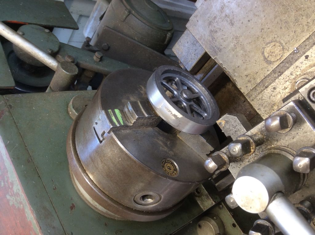
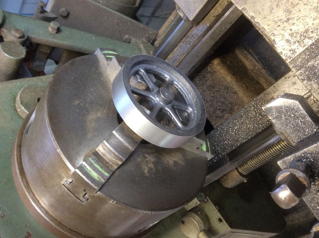
                                          Hi Brian, I'm hoping I can replicate your success when I finally get around to finishing the steam chest and soldering it to the cylinder.. However, in the meantime, I really don't like the idea of packing the wood blocks to give clearance for the flywheel. For finesse, it should look like it looks in the drawings! In my limited experience, cast iron turns as easily as brass. If you've had problems, I think they probably have more to do with the cutting tool you're using, than the size of your lathe. I suggest you find the right tool and then turn down the flywheeel the extra 2.00 mm. To your credit, everything else about the engine is pretty much to spec. It would be a pity to deviate. Regards, Lawrie.

                                          #313879
                                          Brian John
                                          Participant
                                            @brianjohn93961

                                            Duly noted but I have already spent a few hours fidddling around with the aluminium plate and working out how it will fit. I have had a dry run and put it all together without drilling any holes and I don't think it looks too bad at all. The aluminium plate sets off the brass quite nicely.I will be glueing wooden lagging to the cylinder too ; that always looks good even though it serves no purpose. I have some small strips which are already varnished left over from a previous build.

                                            To be honest, I think the supplied cast iron flywheel is too large for this small engine. The small brass flywheel I used in the video looks a more suitable size to my eyes.

                                            You have a good point about using the wrong tool for cast iron. Can you post a photo of the tool you use when turning the flywheels ?

                                            #313965
                                            Lawrie Bradly
                                            Participant
                                              @lawriebradly72996

                                              img_2181.jpg

                                              #313966
                                              Lawrie Bradly
                                              Participant
                                                @lawriebradly72996

                                                img_2182.jpg

                                                #313974
                                                JasonB
                                                Moderator
                                                  @jasonb

                                                  Lawrie, from your photos you have a far more substantial machine that Brian and can hold the flywheel rigidly in the chuck. Brian is right on the limit of what his machine can turn and has to resort to holding the flywheel on a mandrel so no where near as much support at the rim. This result sin chatter and a poor finish, he also does not have much power so has to take many fine cuts with HSS.

                                                  So in this case the wrong tool for cast iron is the lathe not just the cutting toolwink 2

                                                  #313993
                                                  Lawrie Bradly
                                                  Participant
                                                    @lawriebradly72996

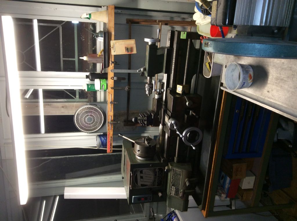
                                                    Hi Jason, Very well observed. I hadn't taken proper notice of the limitations of Brian's lathe. When I was looking around for one a few years ago a wise friend advised that, "You can do small jobs on a big lathe but (obviously) not big jobs on a small lathe." This steered me away from the Myford and Hercus hobby lathes I had been thinking about. As it happened, out walking the dog, I spied a bigger lathe stored in a garage about half a kilometre from our place. To cut a long story short I bought it for (I think) $1,200. It is a Tida model TD-4A and has 10" swing over the bed. Made in Taiwan in 1984. It is a gem. To get it home, I harnessed five mates to a pallet trolley early one Sunday morning and we pushed it, in places up the middle of the road. I'll post a photo!

                                                    #313995
                                                    Lawrie Bradly
                                                    Participant
                                                      @lawriebradly72996

                                                      img_2645.jpg

                                                    Viewing 25 posts - 226 through 250 (of 304 total)
                                                    • Please log in to reply to this topic. Registering is free and easy using the links on the menu at the top of this page.

                                                    Advert

                                                    Latest Replies

                                                    Home Forums Stationary engines Topics

                                                    Viewing 25 topics - 1 through 25 (of 25 total)
                                                    Viewing 25 topics - 1 through 25 (of 25 total)

                                                    View full reply list.

                                                    Advert