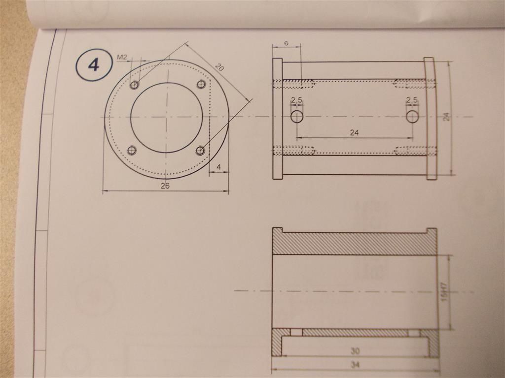
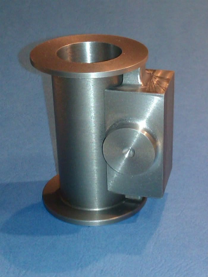
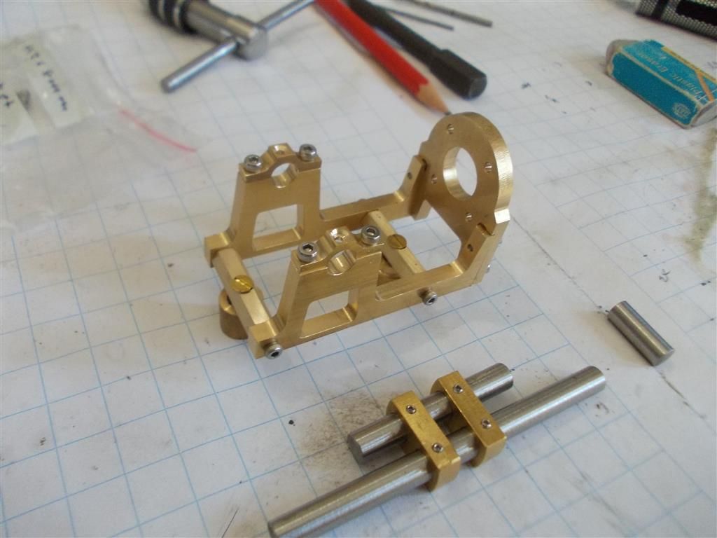
I thought Beng's Danni steam engine would be a simple build but there are a few tricky parts to make. I do not have a milling machine so how can I slice off 4mm from the side of the cylinder ? I did something similar with the cylinder head of the flame eater engine but that was only 12mm thick so I held it on its side in the tool post and sliced it with a slitting saw. But that method will not work here.
Make a filing rest, with two rollers either side of the cylinder to support the file and you will be able to quickly file a very flat surface. Naturally you will need care with the final finishing.
This example is probably over-complex for what you want to do, but it shows the principle. The work is held on a mandrel in the lathe.
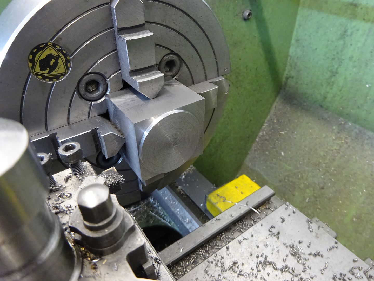
Brian I can't remember if you have a four jaw chuck, if you do mount the cylinder sideways in the chuck, and face it off as you would a bit of bar. Use bits of aluminium to pad between the chuck jaws and the cylinder.
Face it off as Ian SC suggests, but starting from the centre and working outwards, leaving the raised portion unmachined at each end, then file the remaining end bits down by hand where they are slightly curved instead of straight.
It depends a bit too on what goes on that flat. Is it a seal area or a clearance area? Visible or not visible? Slide valve face or to be soldered to something? Makes a big difference to how precise the job needs to be.
I do not have a four jaw chuck. I will leave that for my next (bigger) lathe.
The steam chest attaches to that flat face. The instructions say to solder it on using solder paste. I was thinking of bolting it on and use a gasket to effect a good seal. Perhaps that is being a bit ambitious without a milling machine !
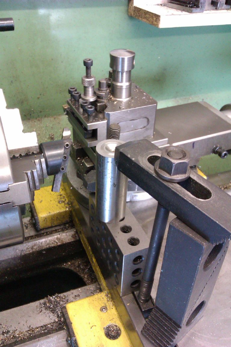
Flycutter in the chuck and cylinder mounted vertically on the cross slide. If the cylinder is also mounted centrally to the lathes centre height and the flycutter set to swing a 30mm radius you won't even have the bits in the corner to file off.
Another method as you are good at silver soldering is to make the central part which can more easily have the flat face machined and then solder on two "washers" to form your cylinder.
Brian, re bolting it on you won't have the thread deoth if you go into the wall of the cylinder but could do it comming from each end
Just wonder if that filing rest Neil linked to used a mill for any of the parts or was it all hand filed
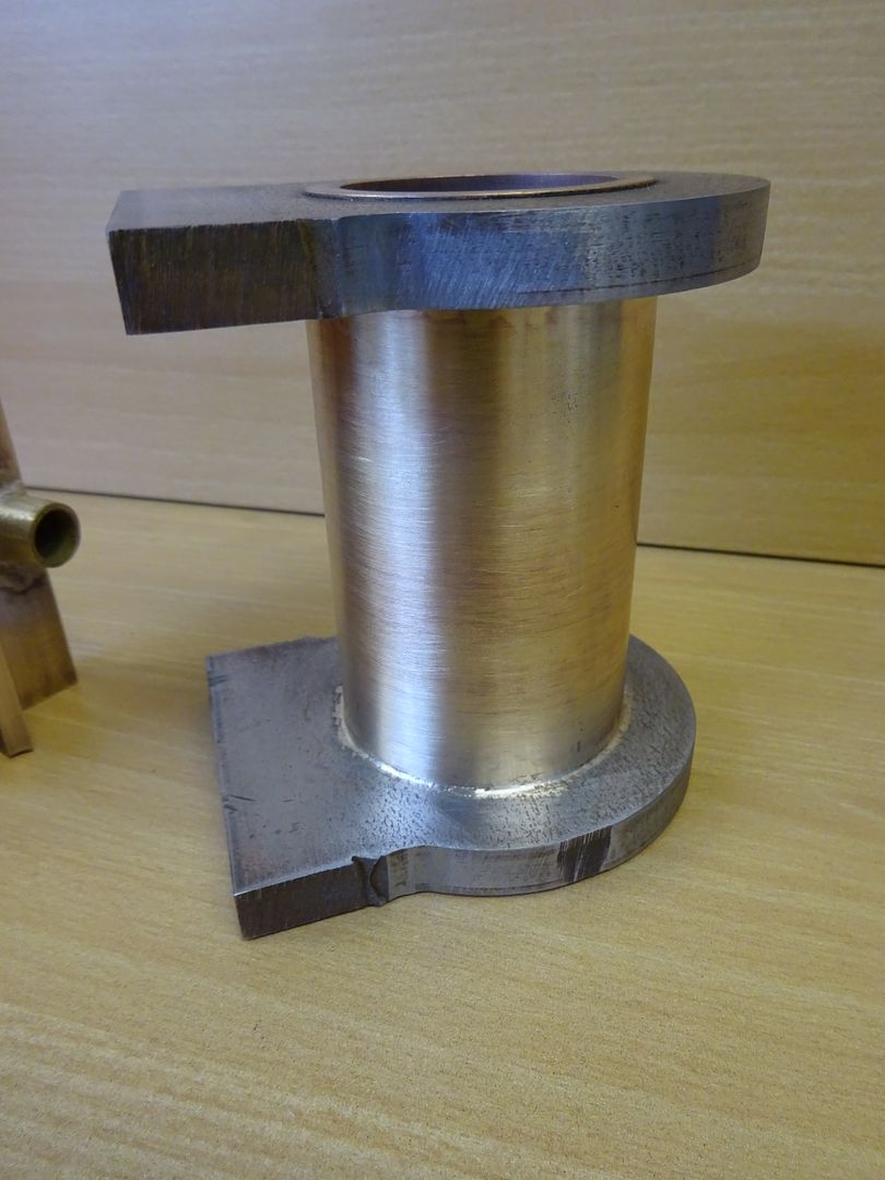
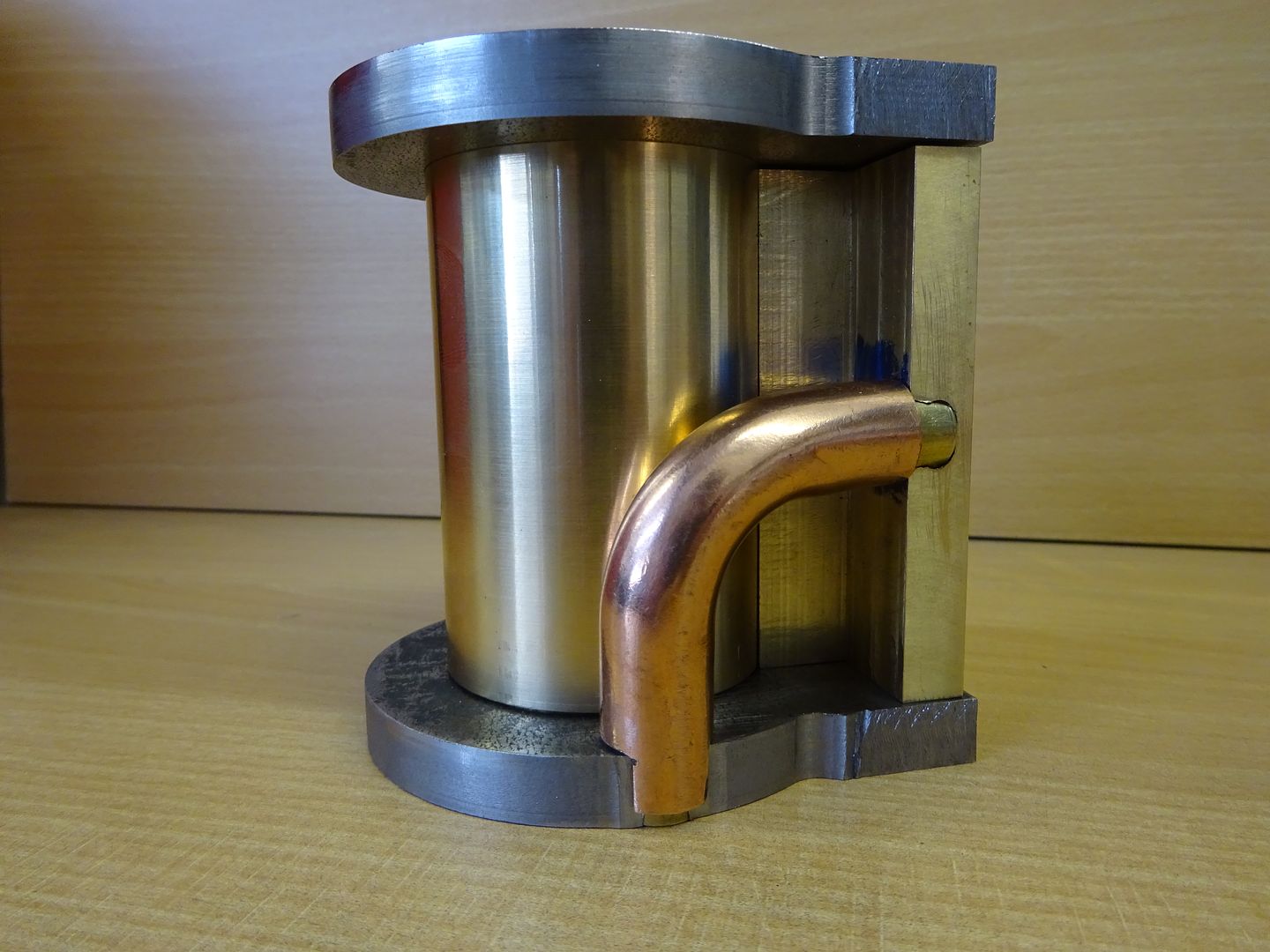
Thinking a bit more if you have to solder on a steam chest it would probably be easier to turn the whole of the central section down to 18mm dia and just make the steam chest with a concave mounting surface.
Bit like this one
Or this
If you had a 4 jaw starting with square stock would also be a relatively easy way to do it incorporating the valve block as one
I usually make the most difficult part first but I will not be rushing into this one ; there are plenty of other parts to make while I give this one some thought.
I did think of making the steam chest with a concave face but dismissed this as probably being more difficult.
The idea of bolting it on was a silly idea….not enough meat on the cylinder. I should have seen that.
The ''cylinder mounted vertically in the cross slide'' : I am not seeing that at all ?
The Taig vertical slide may not fit my small lathe but it could certainly be used on any future, larger lathe so perhaps it would be worth purchasing.
I will look at the Beng's site now. They often have some good ideas.
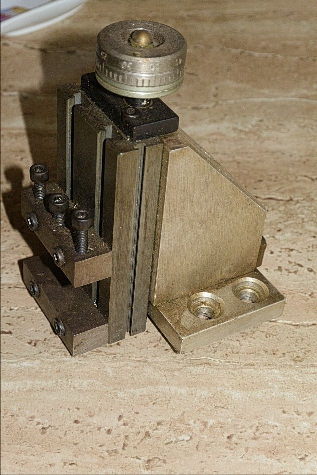
The table on the Taig vertical slide is 3 3/4" x 2" and the mounting base 2 1/4" wide by 2", The vertical travel is 1.4" when the feed thread is at the end of the nut so 1.5" is probably ok. With say a 1/2 dia cutter that means that a 1.9" vertical surface can be milled. Probably 2" in practice. I think they could have fitted a longer feed thread but it's a conservative design so leaves plenty of the dovetail guide engaged, About right actually twice it's width. The width that can be milled depends more on the cross slide travel on the lathe. If parts are reasonably rigid it doesn't matter if they are wider than the table.
The only other dimension you may need is that the table projects 3/4" below it's base in the lower position and the lower "jaw" is 1/2" thick. If you or anyone needs others just ask.
This is mine – didn't sell it with the lathe as they can be useful.
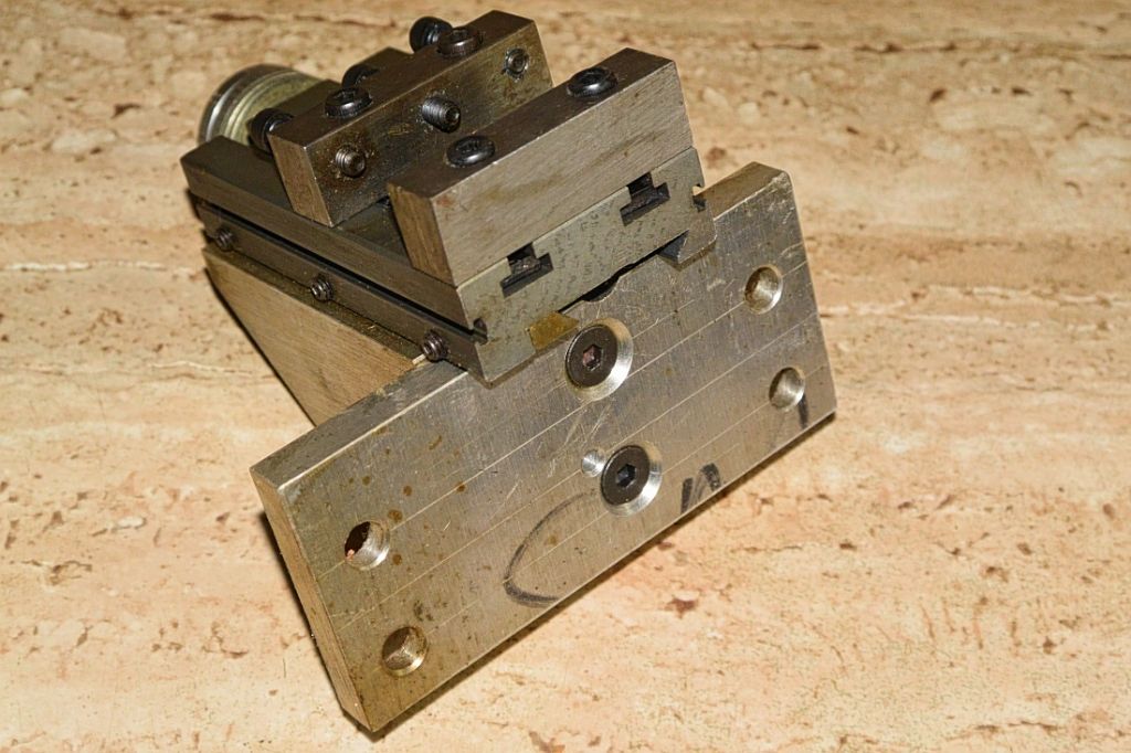
and this is how I mounted the plate on the bottom
I just tapped it's fixing holes but it would be easier to simply fix from the top as it's usually mounted. For a Taig there is a slide down brass plate at the rear so that engages with the slide to make it square to the axis of the lathe.
You have a T Slot that attaches the compound slide so could mount it on a plate and hold it in place with that – 2 T nuts. I've taken the shot with the table right down so that it projects past the base – it's important to allow that to happen otherwise height is lost.
If you do it there will be a need to do some sums to get the max possible travel and that may set how thick the mounting plate needs to be. You may find that it needs to be offset from the T slot to the centre of the lathe so the fixings into it are always in sight or they might turn out to have to be under it. No problem just means fitting 2 parts when needed. I don't think it would take long at all to make the parts needed. I don't think that adaptation actually took me an hour to do
The vice on them looks crap but actually works rather well. It holds things tight and it's easy to make custom jaws in it.
Pass on using these on a mini lathe which might be your next step but I think Neil may have given one of these some serious abuse on one without problem. Some one or the other has anyway.
Fact is a lot more things can be done on a lathe that has a vertical slide, more than people might think.
First thing is to either buy the Taig vertical slide or make some sort of clamp to fit to my lathe. Nothing can be done until then. I think it might be easier to stick with the instructions and machine a flat surface on the cylinder. Cutting a curve on the steam chest is all very well in theory but it might raise some unexpected problems with respect to the ports and threaded holes.
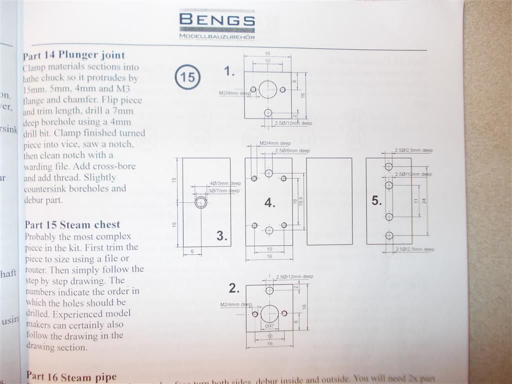
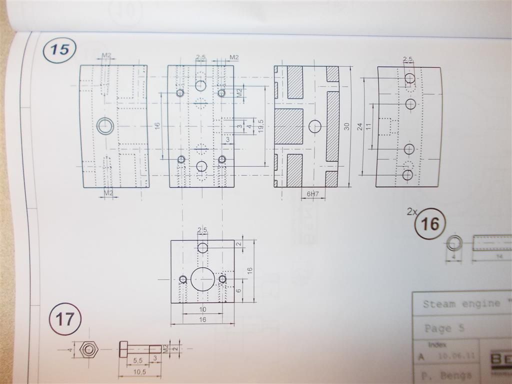
Below are two drawings of the steam chest. Forgive my ignorance but why are there 4 holes on side 5 ? I thought this was the side attached to the cylinder and that only has 2 holes to be drilled in it.
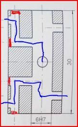
The two inner holes are actually blocked off when it is soldered to the cylinder. in the same way that the two holes drilled in from the ends are.
This is a fairly common way to get the steam passages into a solid block of metal rather than them being cast in on a casting. If you look at the section on teh second scan and imaginge these holes closed you will see the steam flows in a "S" direction
If you do buy the Taig slide Brian at some point you could increase the vertical movement by a fair amount by making an extension for the feed wheel and a longer lead screw. They don't do this because it would hit the bed of the lathe. Packed up to suite the centre height of your current lathe I don't think you would have that problem but you would need to check against the sizes I quoted. They have imperial graduations by the way. Not sure if metric is available. They use 0.050 per turn with 0.001 " graduations. I guess they could be fitted with M6 all thread and then 1/2 division would be 0.1mm
There is another option as well. Something it seems all Rolls Royce apprentices used to have to do. Make an "angle plate" to attach the compound slide to and fix to the cross slide and use that instead. The angle plate could be all sorts of things including maybe a length of largish sized aluminium square section or what ever that can be found that looks to be suitable. The usual problem with this sort of thing is similar to mounting a Taig slide on the cross slide where the toolpost usually goes – it's likely to be much better offset towards the centre of the lathe to make full use of the travel. That can be done in the same way as I suggested for the Taig slide or maybe the part used may be big enough to do that.
I'd guess that the Rolls Royce lot did it all on a lathe and maybe a drilling machine but they would have a face plate and 4 jaw available however Jason has shown how a flat face could be fly cut onto some bar standing on end and lathes can drill with the drill in the chuck and work on the cross slide. There are probably all sorts of options.
I like the handle extension on the cross slide Neil. Must have been hard work milling the slots or maybe you have soft hands or a blunt cutter.
It looks like it fits on a mini lathe fairly well.
Glad you posted that because Brian's repertoire could be extended a fair way with a vertical slide and Opti might do a small light weight miller with a fault. Might make for another long thread though. Plus of coarse millers tend to need to more weight than small lathes due to rigidity problems.
I remember months ago somebody warned me about fitting a vertical slide to my lathe. They said the lathe would be too small to give good results. However, the parts need to be made and if the slide does not work out then it will be used on my next lathe when I buy it. At this point, I am not quite sure how it will fit on my cross slide but I hope things will become clearer when I have it in my hands and I can see the fittings, slots and holes.
You may need to take it easy with cuts Brian but it wouldn't surprise me if you didn't even need to do that. I most certainly didn't need to on the Taig. It would easily cut a slot in from the edge of a piece of 3/8 m/s with a 1/2" end mill and then add a recess in that with a 1" dia woodfuff key cutter. That was cutting at it's full diameter at the end of the slot. Feed rate may have been a little slow compared with a miller but in real terms as fast as I would have done it on a real miller anyway. Only problem really on the Taig is that this probably isn't good for the headstock as it's in 2 parts that can move under load. No signs of that though but some later rather heavy turning did distort the head.
You may need a DTI and small stand to square the vertical slide up to the lathe's cross slide at some point. The brass plate on the back of them does this on a Taig. There will be some way of achieving something similar on your lathe but it will still need setting up. Maybe a similar brass plate that rests against the front side of the cross slide if you mount it on a piece of plate.
Machinery House from whom I bought the Optimum lathe have a generic vertical mill slide which will fit my lathe. I simply remove the top slide by undoing one bolt and use the same bolt to attach the slide to the carriage. I am not sure if the Taig attaches so simply. The generic slide is also metric.
They also have the four jaw chuck for this lathe but that will only be of use for this machine whereas I can use the vertical mill slide on any lathe.
Machinery House from whom I bought the Optimum lathe have a generic vertical mill slide which will fit my lathe.
.
Brian,
I cannot advise from experience [as I only have Myford and Pultra vertical slides] … But I think you will find John and Neil recommending the Taig. … it appears to be well designed and constructed.
And before you part with your cash maybe John W could give a few sizes so you can make sure it will fit your machine. Bearing in mind you are rather limited on the facilities to do any modifications to the mounting method etc.
Taig Australia have not responded to my emails nor is there a phone number on their website. Machinery House do not have the generic milling slide in stock and will not have them until November…..even that sounds like ''maybe''. So I will have to source something from overseas.
This looks good but I often have problems when ordering from India :
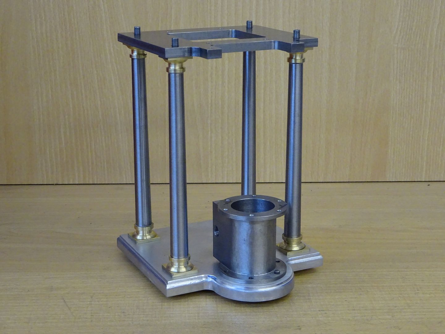
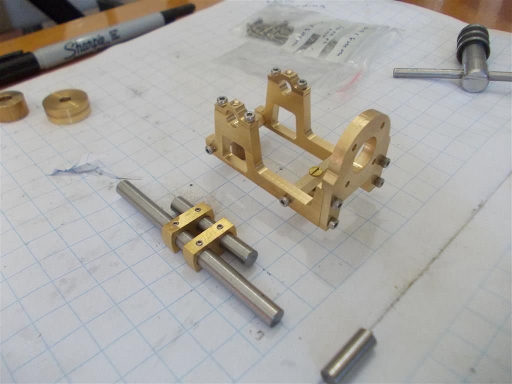
In the mean time I have completed all the drilling and tapping for the frame and supports. I am using socket head bolts rather than the supplied hex head bolts as they are much easier to work with. I have also substituted hex bar for the supplied square section bar for the two cross supports as the hex bar is much easier to tap and drill on the ends. The square bar would have required a jig for that. I am surprised that they have not used bearings in the crank supports.
I am still having problems with the crank : I should have drilled them together as they are not parallel with each other. I will have to order another set of crank plates and give it another go.