Hardy & Padmore “Ideal”

Advert

Hardy & Padmore “Ideal”

Home Forums I/C Engines Hardy & Padmore “Ideal”

Viewing 11 posts - 1 through 11 (of 11 total)
  • Author
    Posts
  • #763285
    JasonB
    Moderator
      @jasonb

      I was originally asked by Graham Corry of Alyn Foundry to make a small additional boss that could be grafted onto the patterns I had previously made for the Nattie Flywheel as he wanted to use these flywheels as a basis for a model of the Hardy and Padmore Ideal engine which has a similar operation to the Loyal Cycle known as the “Southhall Patent”.

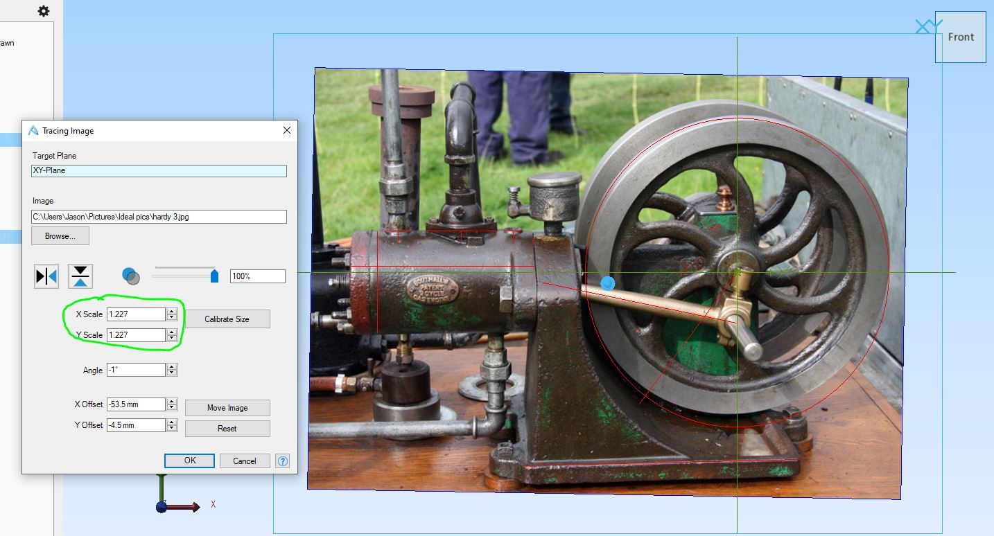
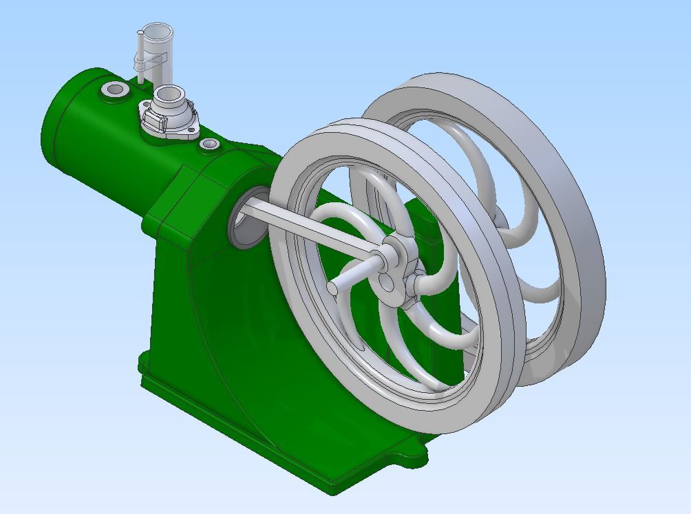
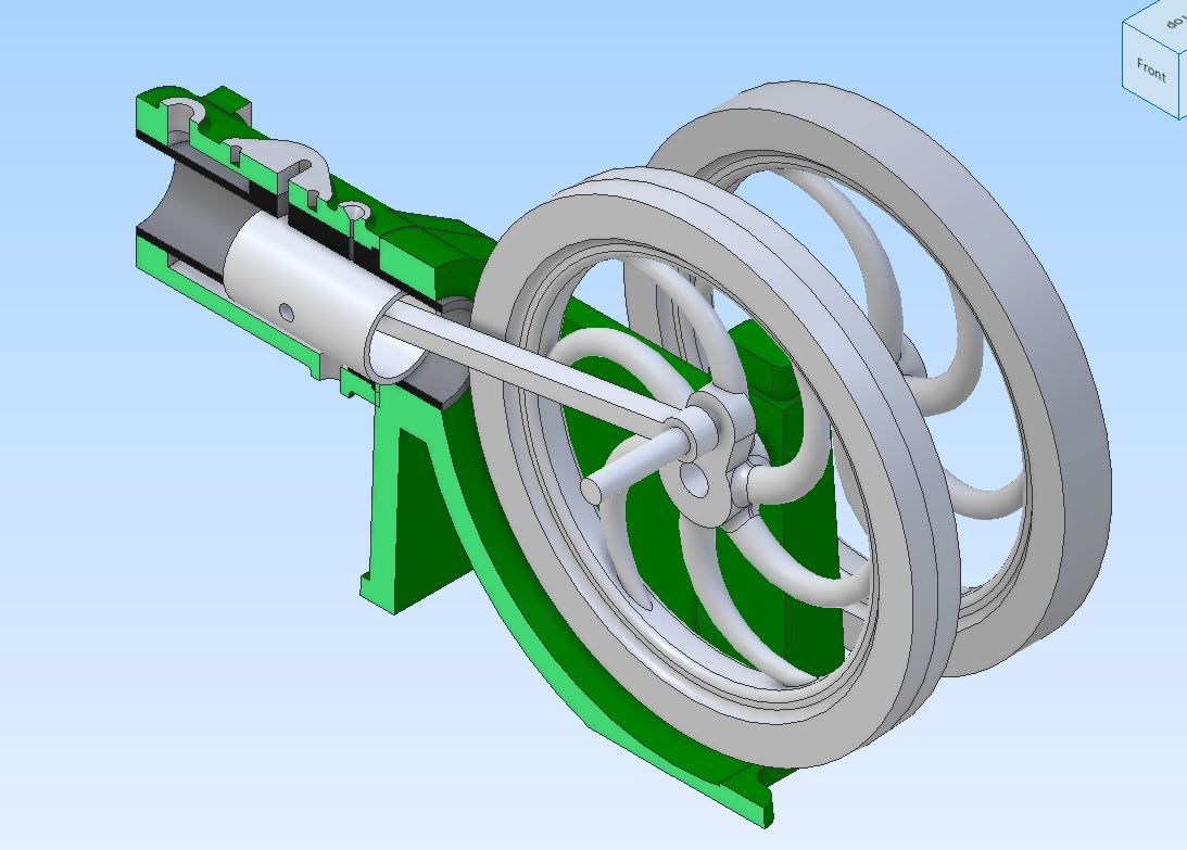
      Around April of 2023 Graham and I had an excahange of messages his pattern for the engine bed was not fitting the flywheel very well and it ended up with me designing a version from scratch to suit these flywheels which are 122mm finished size worked out at around 4/10th scale. There are only two of these engines known to exist so very little to go on. A couple of engravings and a small photo of one but there was a reasonable side view of the other which was imported into Alibre and scaled to suit the flywheels.

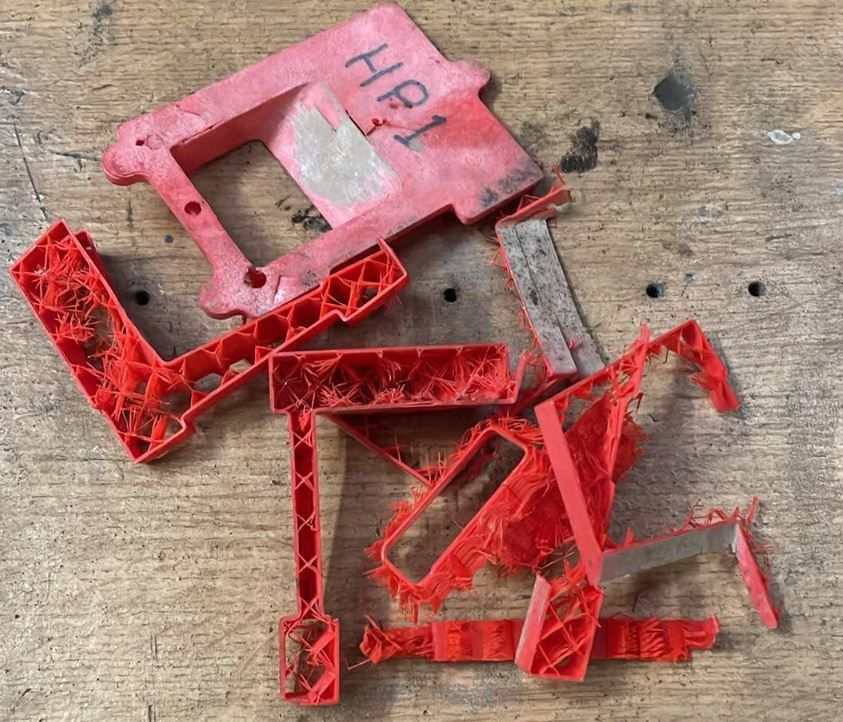
      I was all prepared to machine the patterns for this new engine when Graham messages to say he thought it was time that Alyn Foundry got a 3D printer and what did I suggest. Not long after the suggested Bambu Labs PS1 arrived and the pattern files created and sent to Graham. The fit of the flywheel was just right so the rest were printed and sent off to be cast

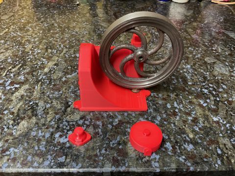
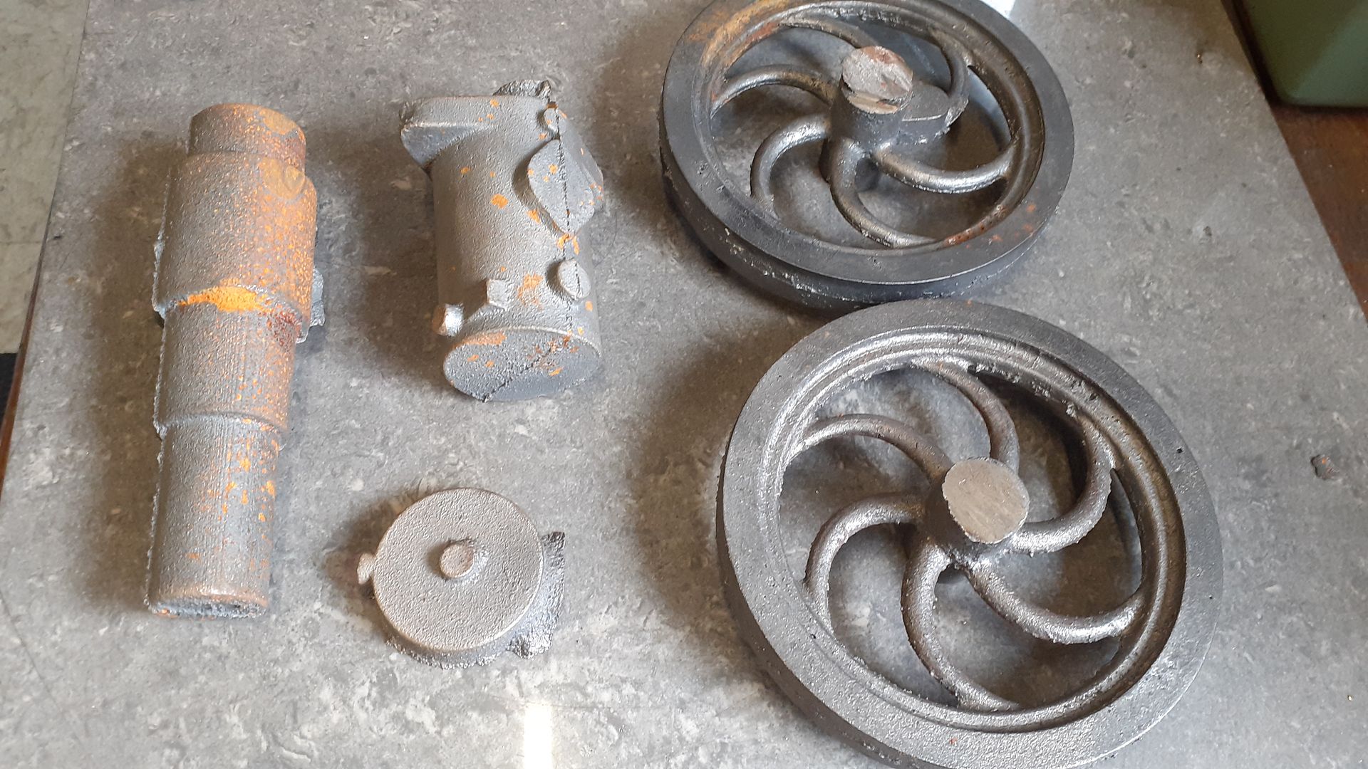
      It is probably best to say that a lot was learnt from these early 3D patterns. Two sets of castings were produced with the exception of the bed casting as the pattern did not survive removal from the air set sand for a second use.

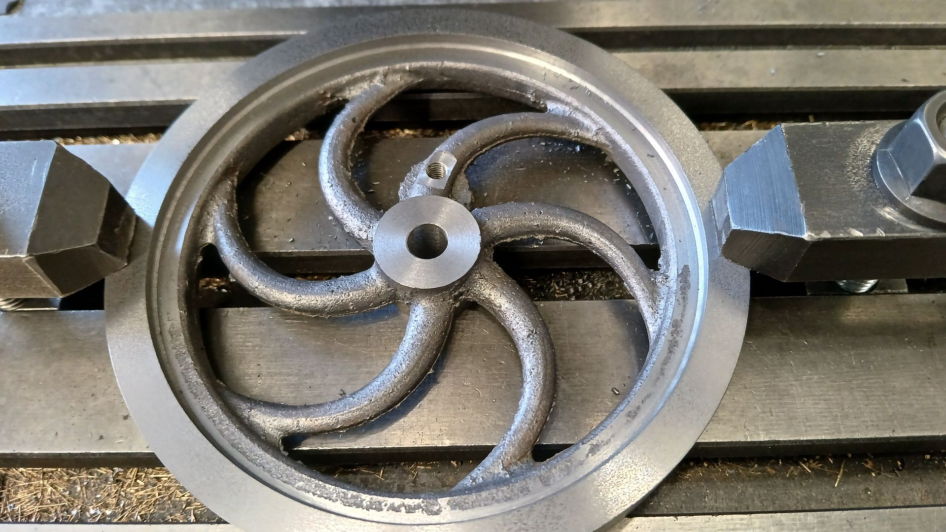
      So I only got a partial set, You can see the additional boss on the top right flywheel, this is where the crank pin goes.

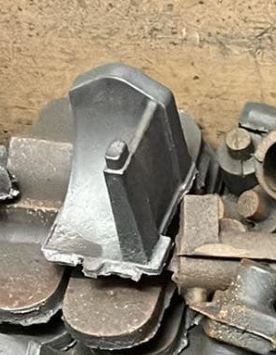
      A new pattern was printed with thicker walls and a higher percentage of fill and a new casting done but it has been sitting at the foundry for a while and only arrived here last week.


      Advert
      #763286
      JasonB
      Moderator
        @jasonb

        I had not intended to make a start on this one quite so soon but it would seem a third set of castings has found it’s way to one of our members who is eager to get going. I only did a few quick preliminary 2D drawings for Graham to use on his engine and they lack the smaller details and are not checked against the actual castings so it really needs this engine to be built so that working drawings can be provided.

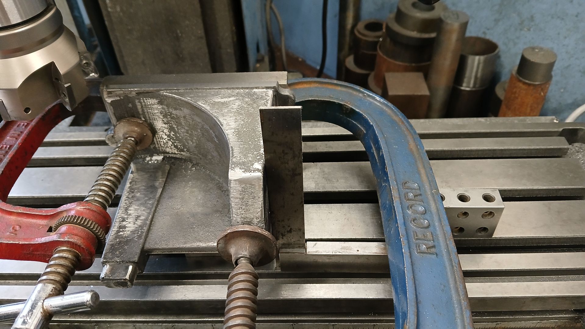
        I made a start fettling the bed casting followed by flattening the bottom surface enough so that there was contact under the three feet and no rocking. I was then able to clamp this flattened base to an angle plate and checking that the cylinder mounting flange was as close to vertical as possible took a fine skim off the edge flange that runs full length down that side of the bed to use as a reference surface. It wa salso reassuring to find that this thin lip had no signs of chill.

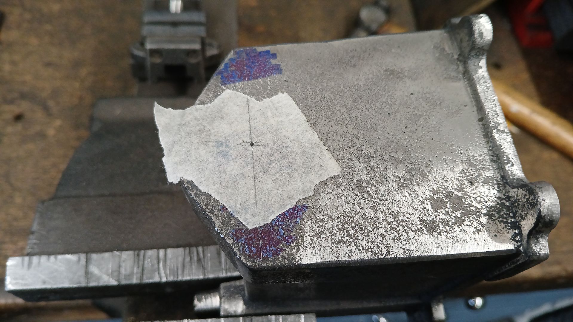
        I then used the height gauge to scribe the horizontal ctr line of the cylinder and crankshaft onto the casting. The width of the cylinder mounting flange was divided in half and the position marked with a punch.

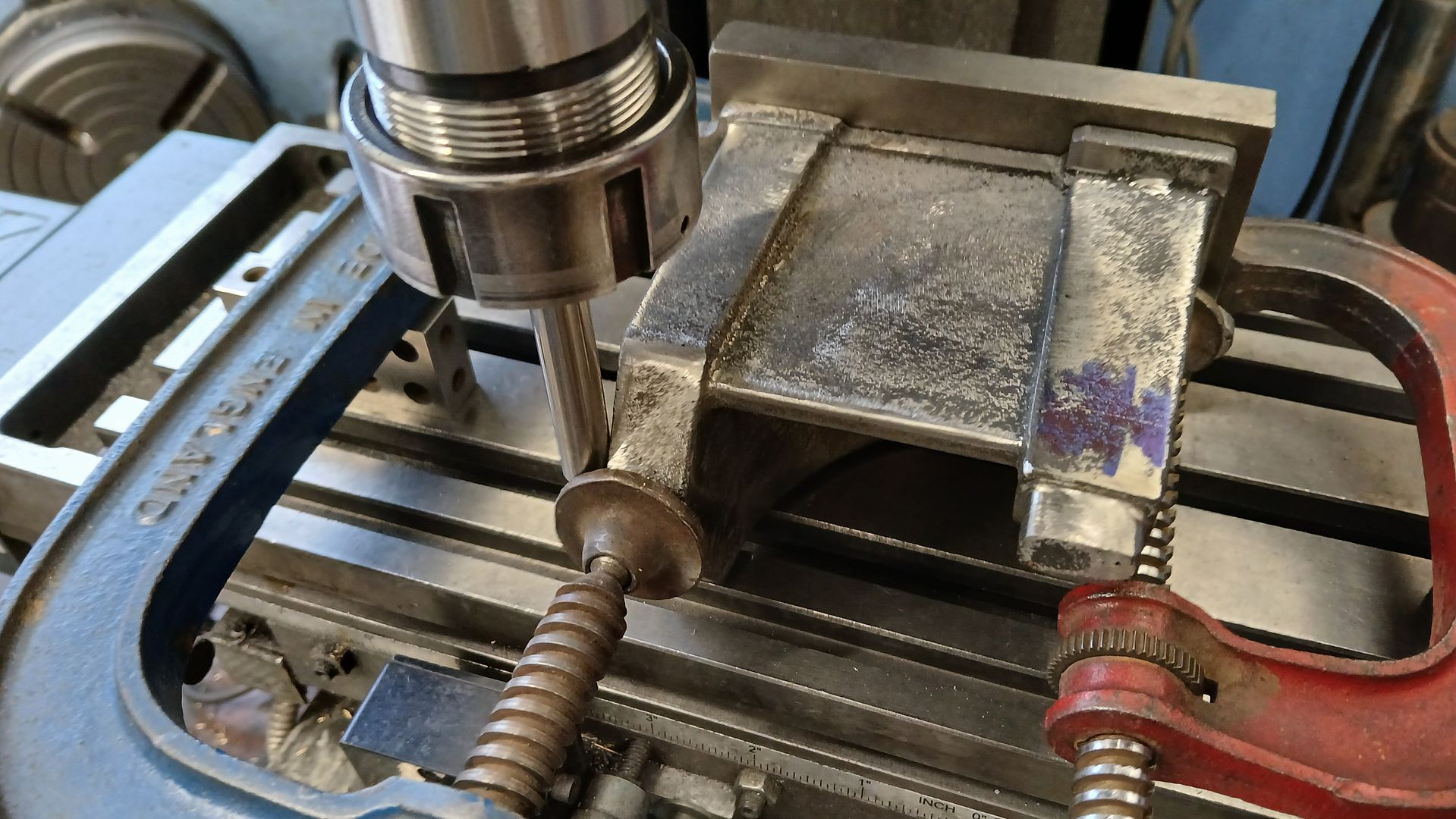
        The bed was once again clamped to the angle plate but this time the ref surface was set flat against the mill’s table. I used a ground rod to touch off at the very top of the casting and then moved down the required distance to see how things measured up.

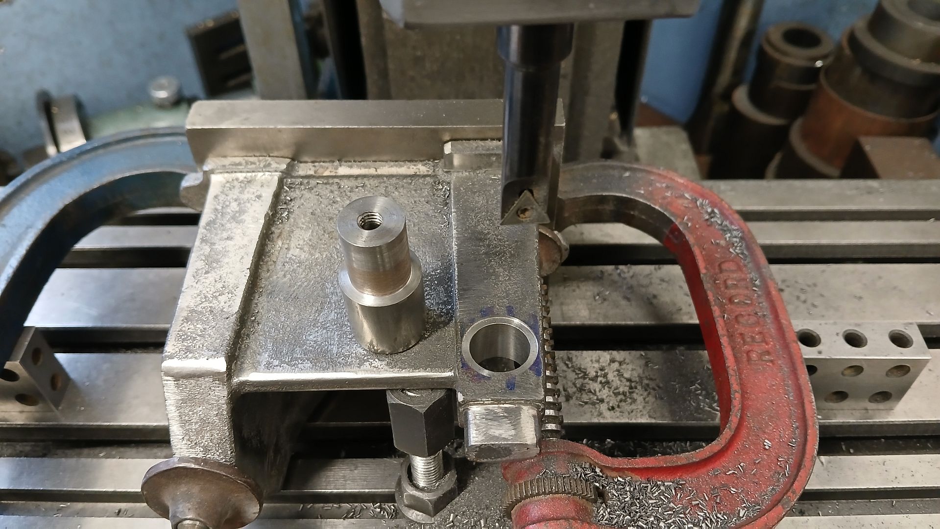
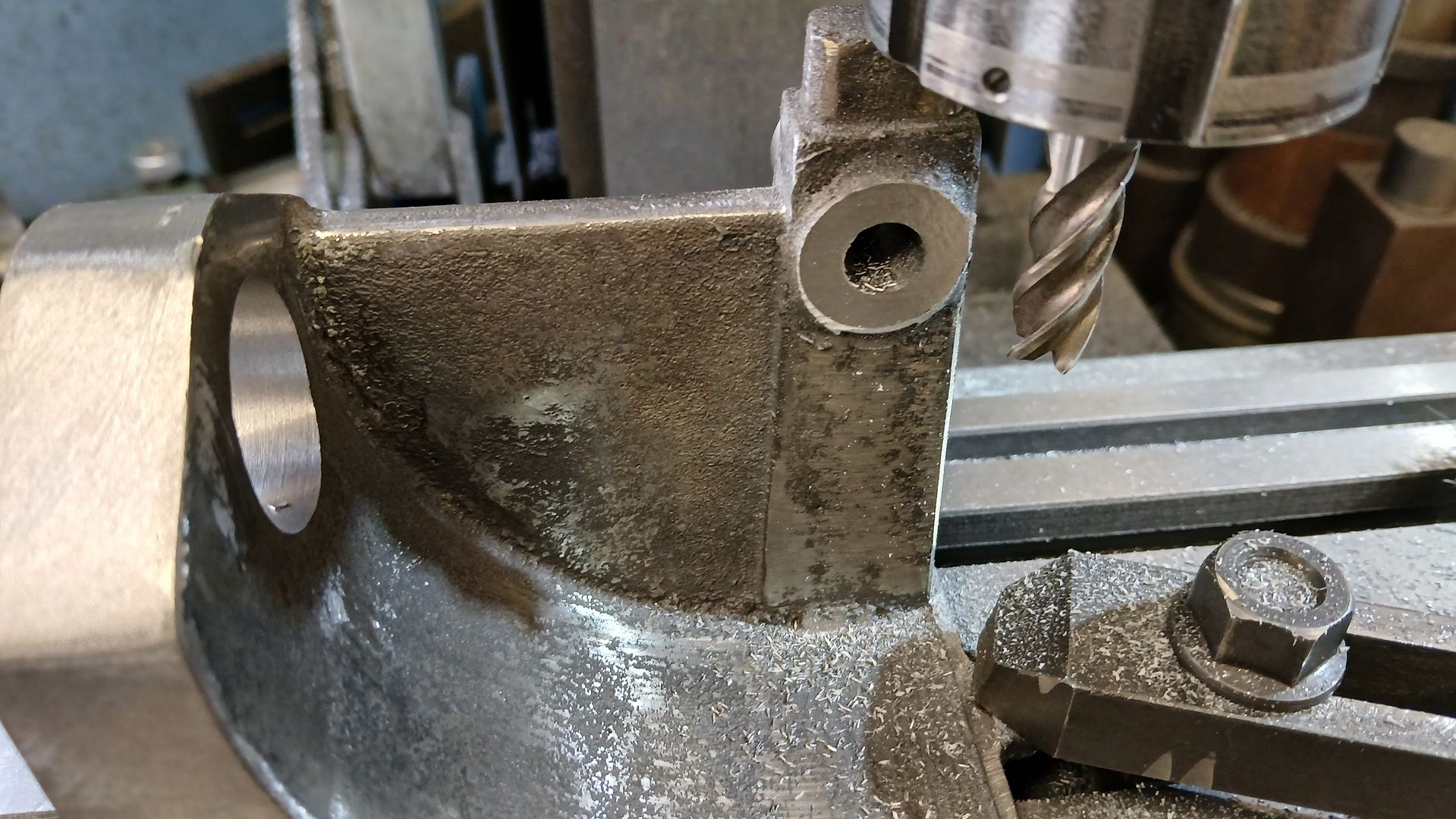
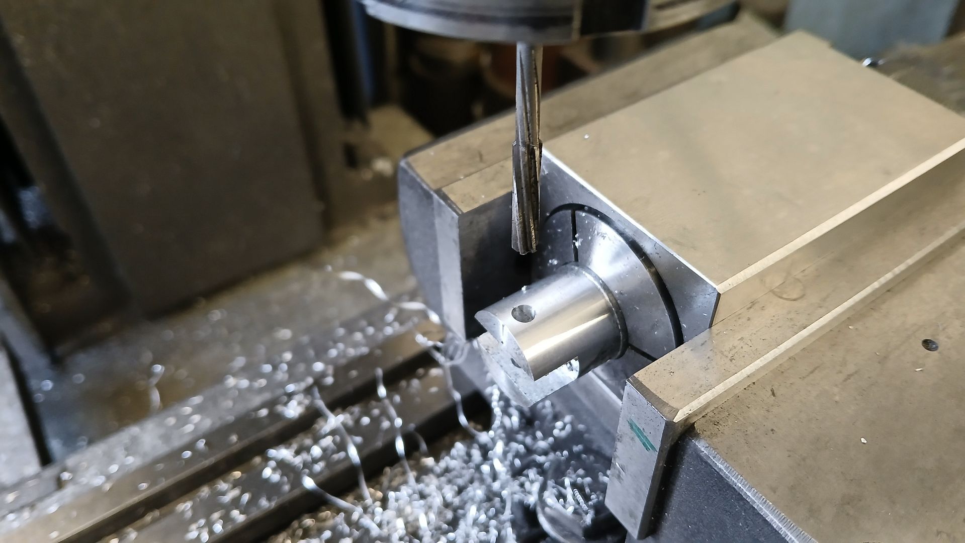
        The crank position was just a bit more than the distance the mill had been moved which was perfect as it allowed a small amount that was later milled off the cylinder mounting surface. I should say that during the design it was decided not to cast the boss that sticks out either side to take the crankshaft bearings as it would have meant some complicated parting lines. Instead a piece of bar would be JBWelded into place and then machined. So with teh ctr line of the crankshaft now located a hole was bored to take the previously turned boss, I also cut a small counterbore to just remove the draft angle so the step on the boss had something to bear against. There is a “washer” that foes on the other side to bring the boss back upto diameter.

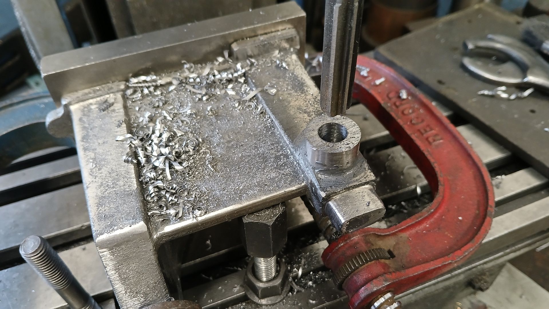
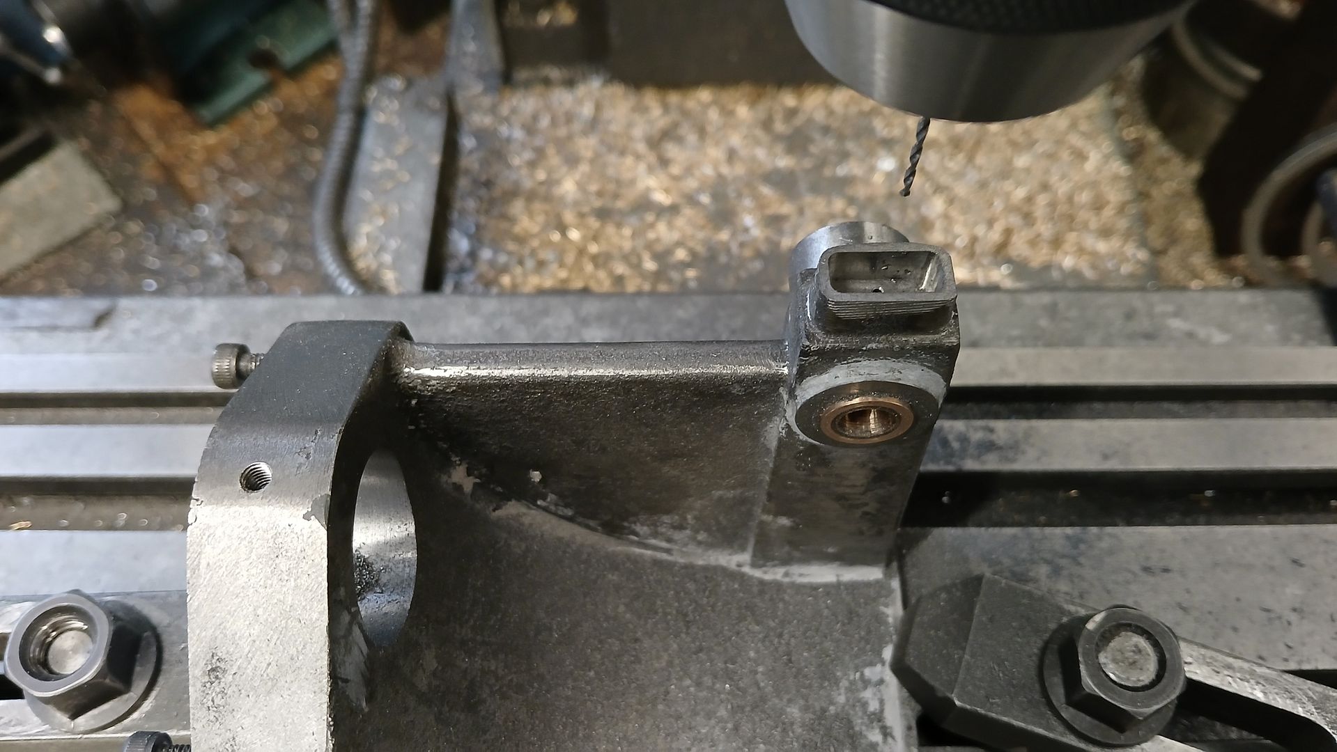
        After allowing the JBWeld to set the boss was milled to height before drilling and reaming for the bearings.

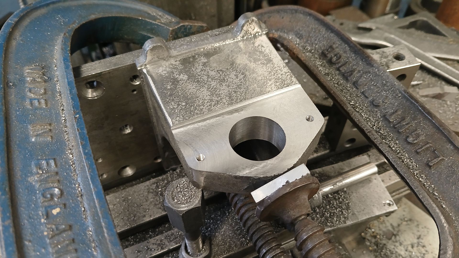
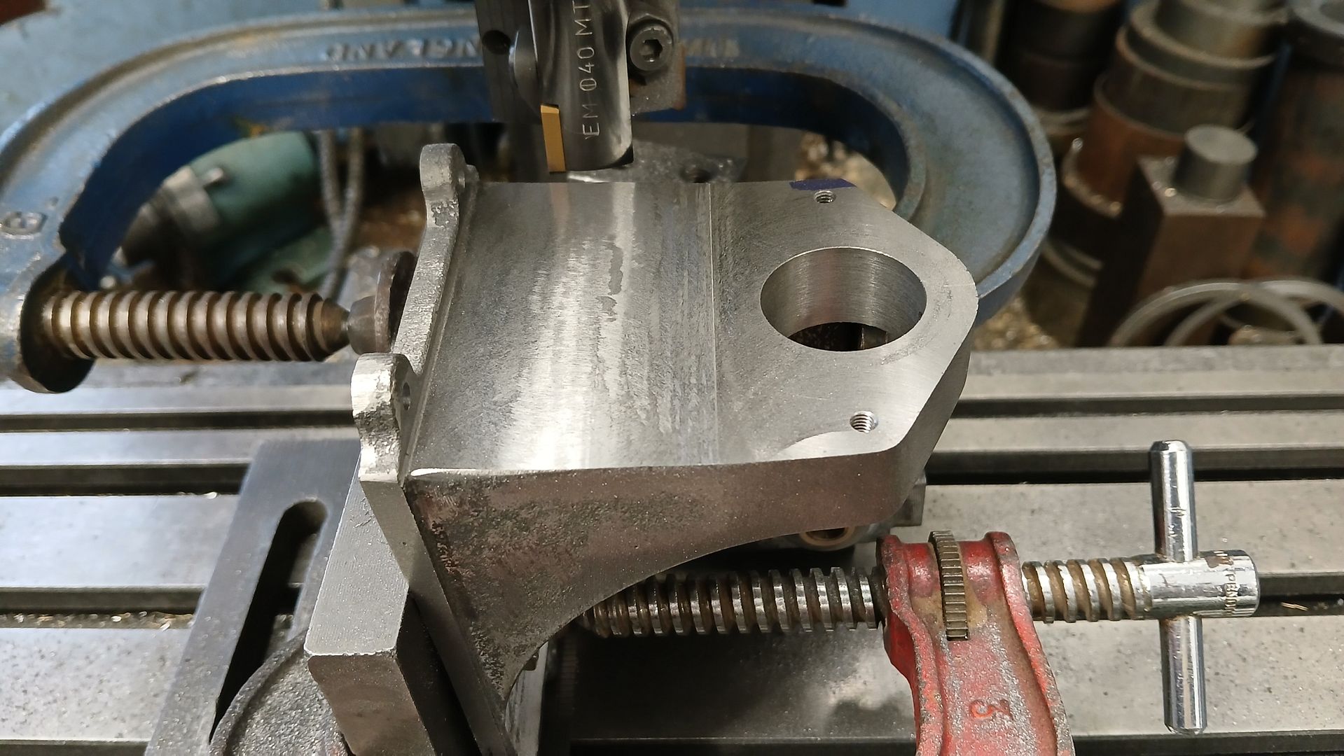
        The bed was then rotated 90degrees on the angle plate and the ref surface checked for vertical, the punch mark located and the DRO zeroed. I then milled a flat surface for the cylinder to mount on, the metal to be removed got thicker towards the bottom due to the draft angle. Have not yet decided if I will leave the step or blend it in.

        At the same setting a hole for the forward facing part of the cylinder liner was bored and two holes drilled and tapped for the cylinder mounting studs.

        #763302
        duncan webster 1
        Participant
          @duncanwebster1

          Here’s an article by ‘ETW’ who I assume is Edgar Westbury explaining how it works

          https://www.modelenginenews.org/etw/systeme_loyal.html

          #763310
          Diogenes
          Participant
            @diogenes

            It’s a very good choice of subject for a model – don’t think I’ve ever seen one of these constructed so will be interesting..


            #763311
            JasonB
            Moderator
              @jasonb

              Thanks Duncan the image that shows the five stages of the cycle is very similar, H&P had the exhaust valve as a pivoting flap rather than a sprung valve as shown. The model is not going to use a flap as it would be very small at this scale though a reed type valve was considered. The engine I have based it on did not have the governor. Also at this size a scale looking hot tube is not very practical so may be spark ignition. Graham has had his running but with a non scale hot tube but more of that later.


              hardy 5

              Description of how it worked (fig 2B)

              414668498_1857940761326633_6605536836872372285_n

              Although I have built other models based on the Loyal cycle I have not seen this one modeled before. I hav made the engine top right and almost completed another of Nick’s designs. This H&P will see the one on the left done and I have also made a start on the drawings for the early Loyal bottom right.

              loyal 0


              #763312
              Ches Green UK
              Participant
                @chesgreenuk

                Jason,

                Thank you for all the builds you post, including this one. Very fascinating stuff.

                Ches


                #764956
                JasonB
                Moderator
                  @jasonb

                  Good to know you are enjoying them.


                  The only other thing I have done to the base is to machine the other side of the crankshaft housing back to 19mm from the engine ctr line and then tidied up the JBWeld fillet. I tend to leave the excess filler/adhesive in place until after machining as it probably makes for a slightly more supported joint.

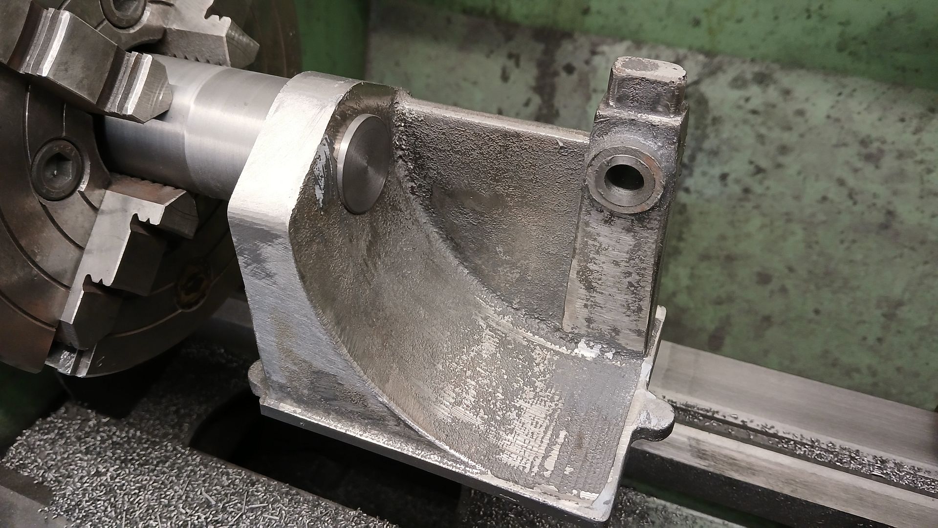
                  My cylinder came out really well with a good finish and no signs of layer lines from the pattern. We decided not to core this as it is quite a small casting and the cost of the extra material is minimal.

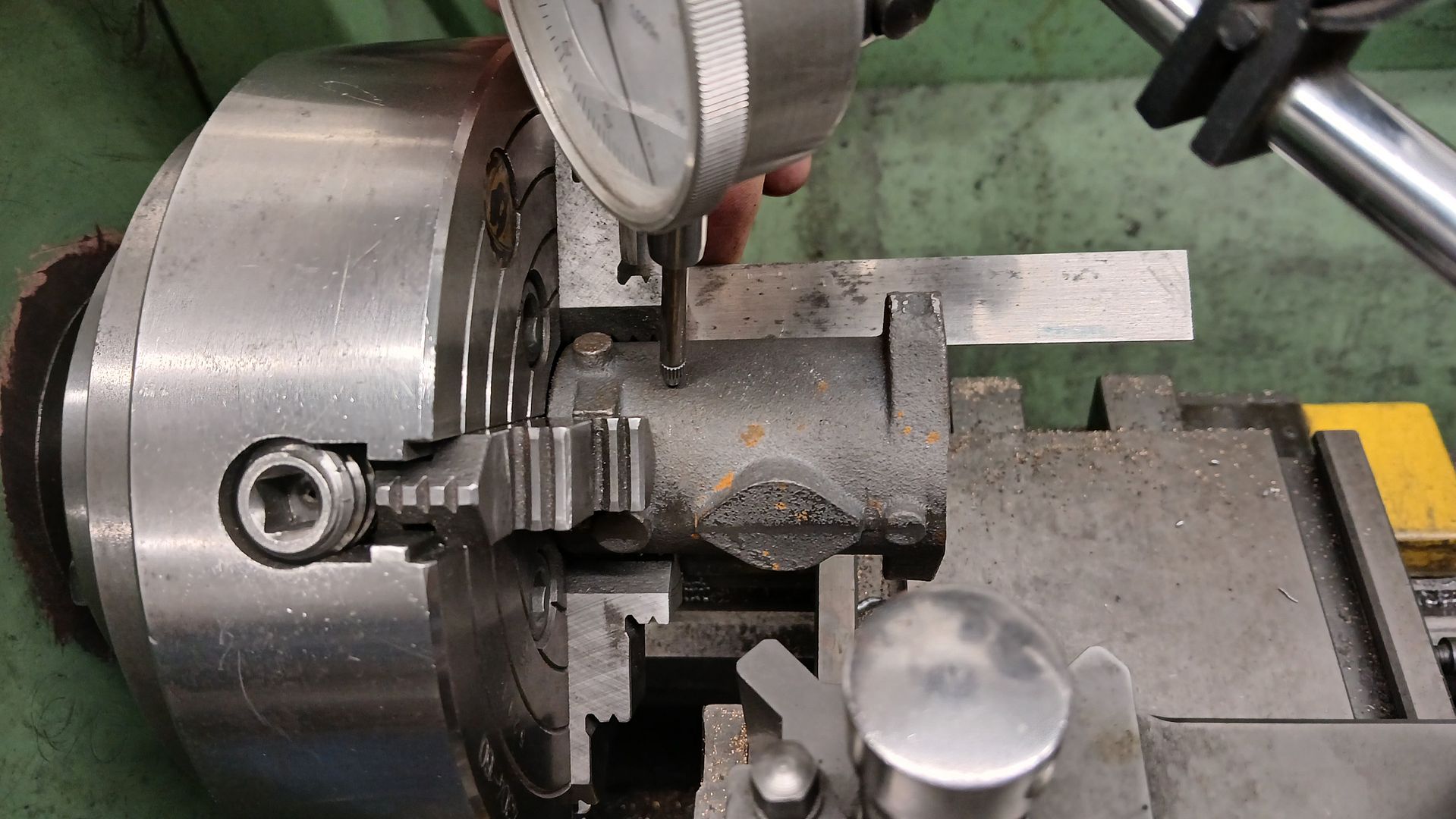
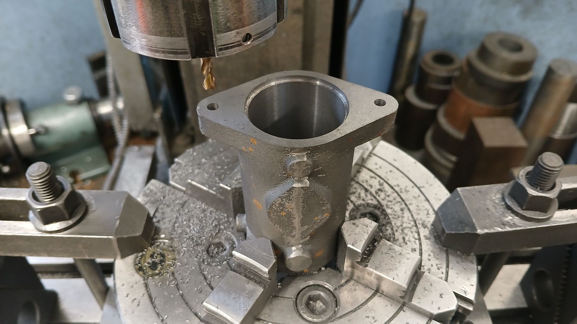
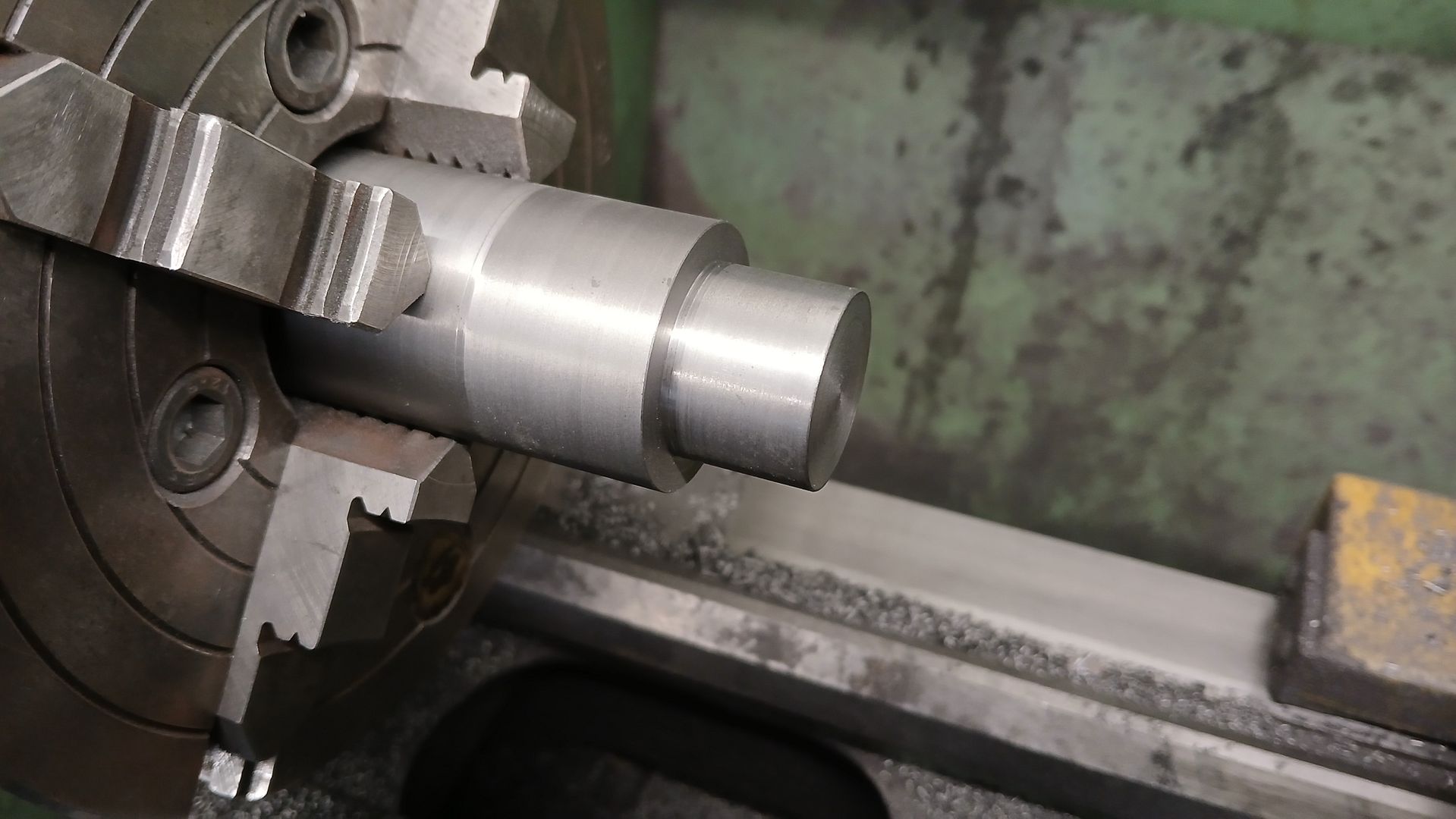
                  I set it up in the 4 jaw getting the head end as true as you can with a cast surface, the dti was used to get North & South and East & West even together with a square to make sure things were as true as possible.

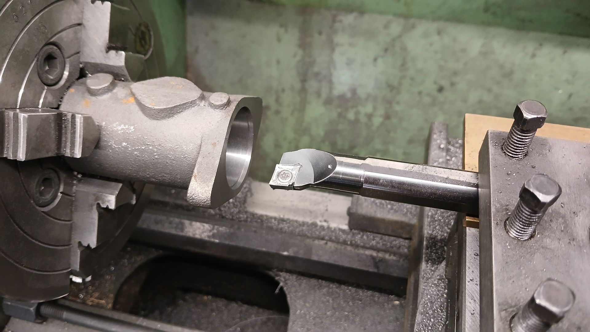
                  The flange was then faced back to leave it the correct distance from the middle of the first cast boss and then it was bored. There are three diameters. 26mm at the head end, 33mm for the water space and 35mm for a small lip on the liner to locate it’s position length ways.

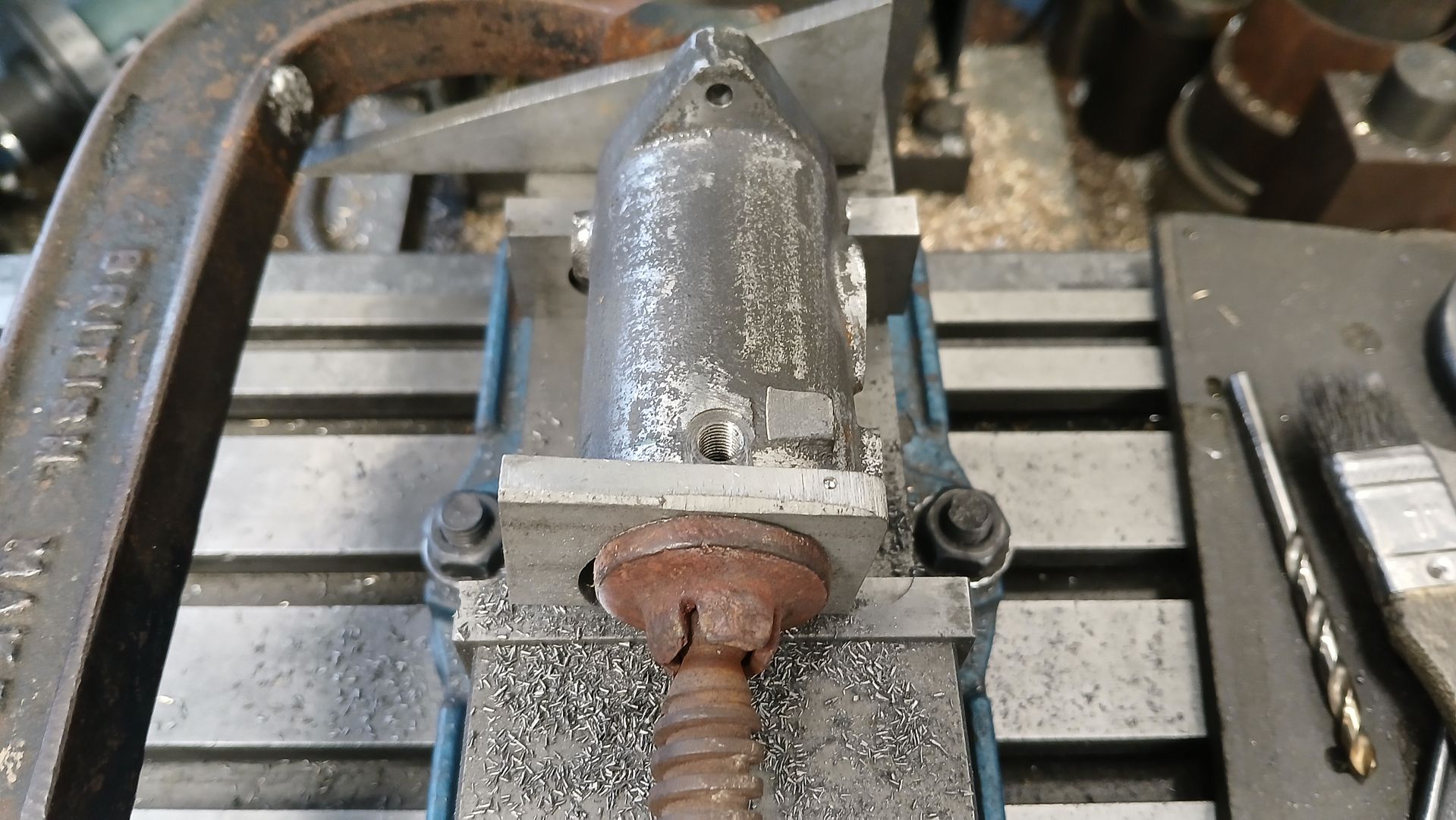
                  I then moved the 4-jaw to the mill so that the two mounting holes could be drilled perpendicular to the face of the flange

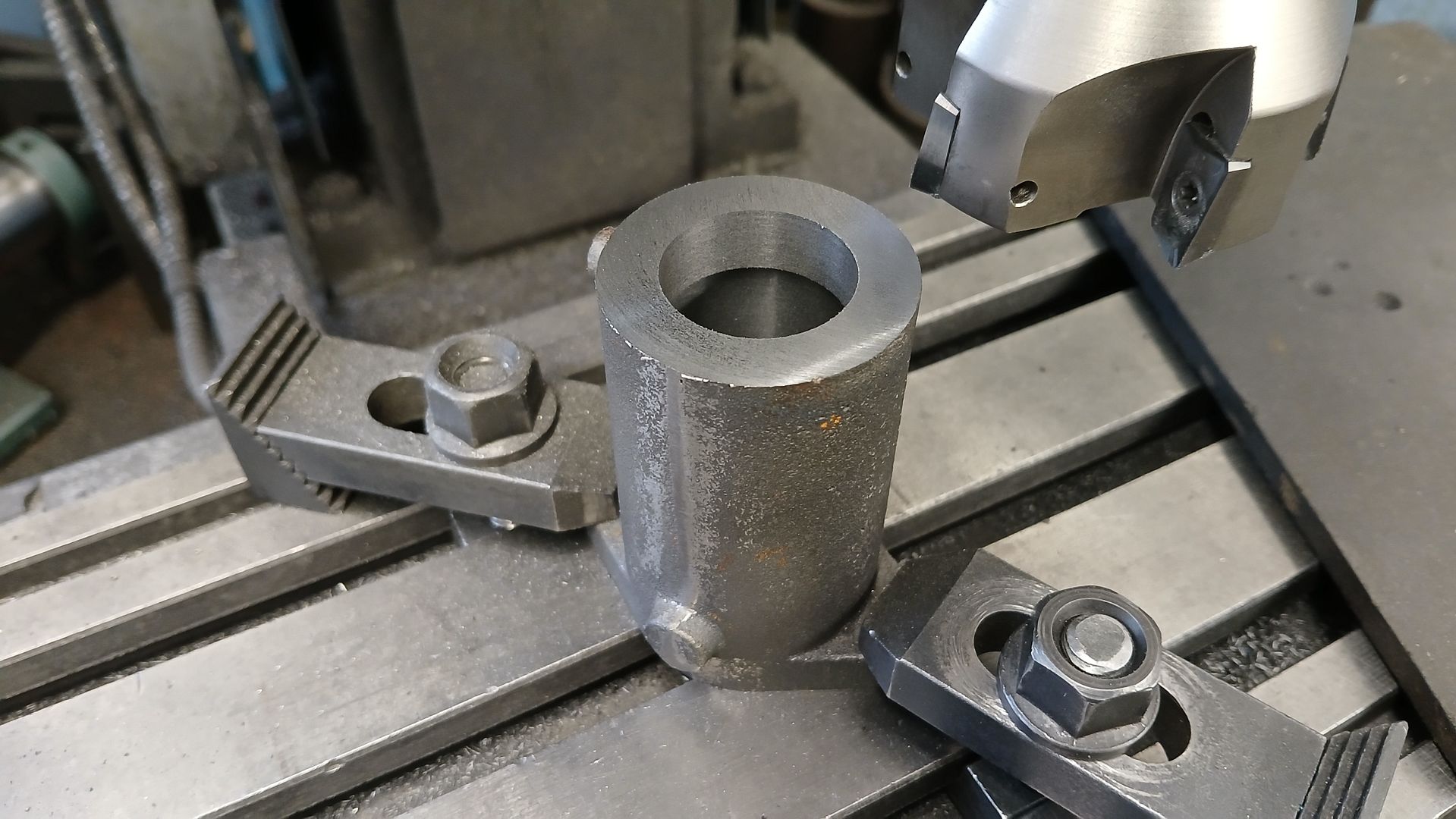
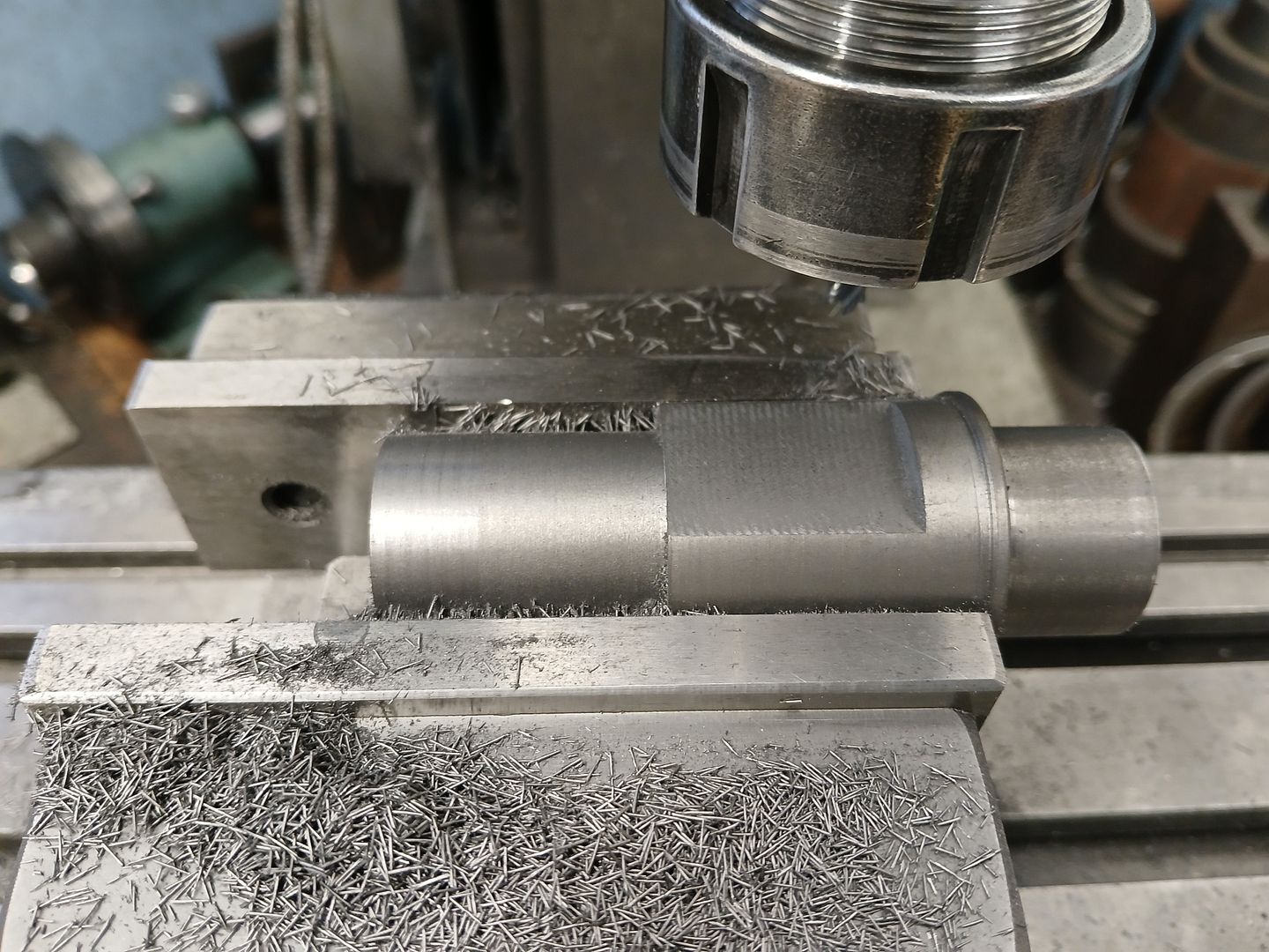
                  The head end of the cylinder was milled flat but I left an extra 0.5mm so it can be taken to final length once the liner has been Loctited into place.

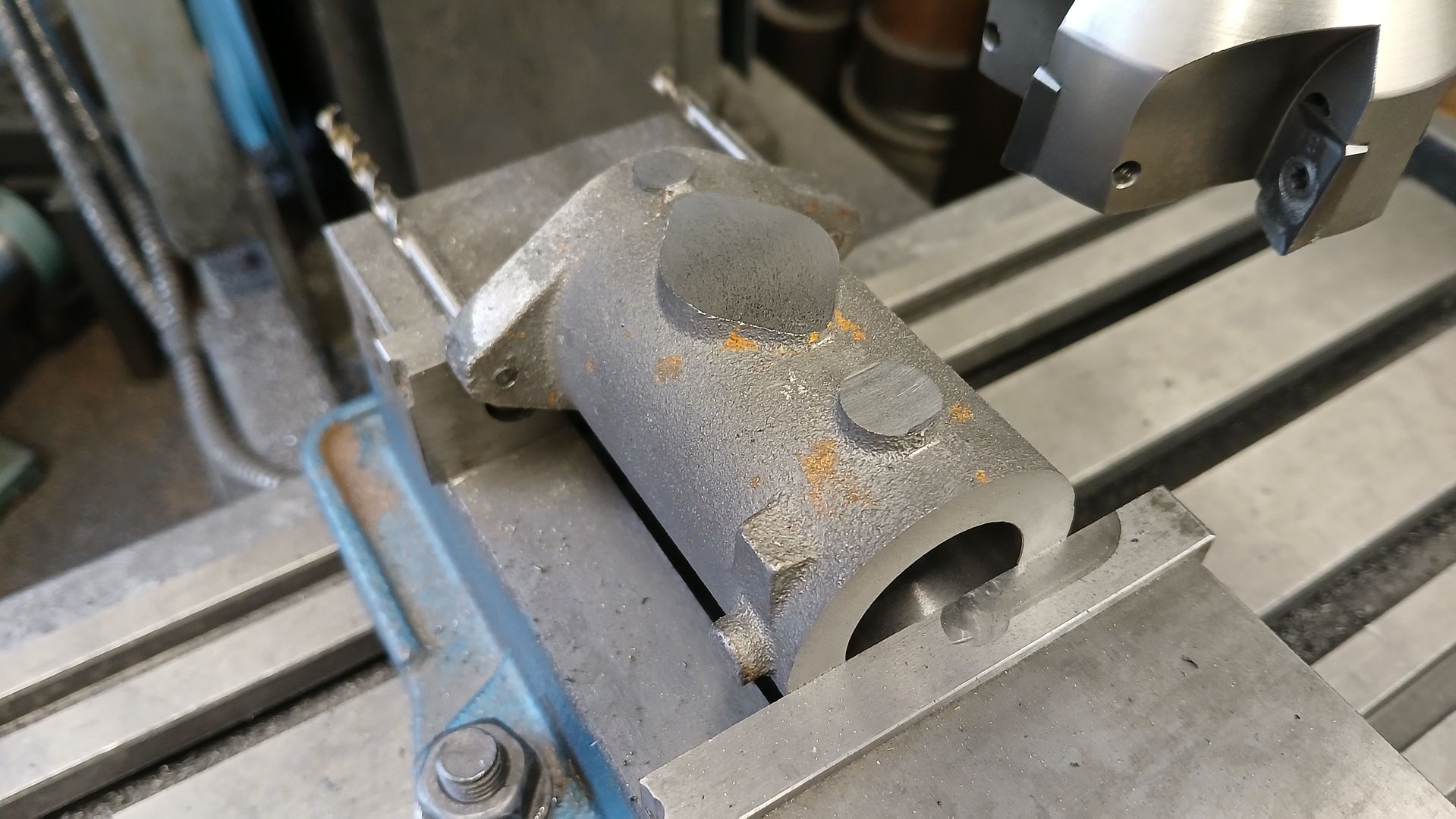
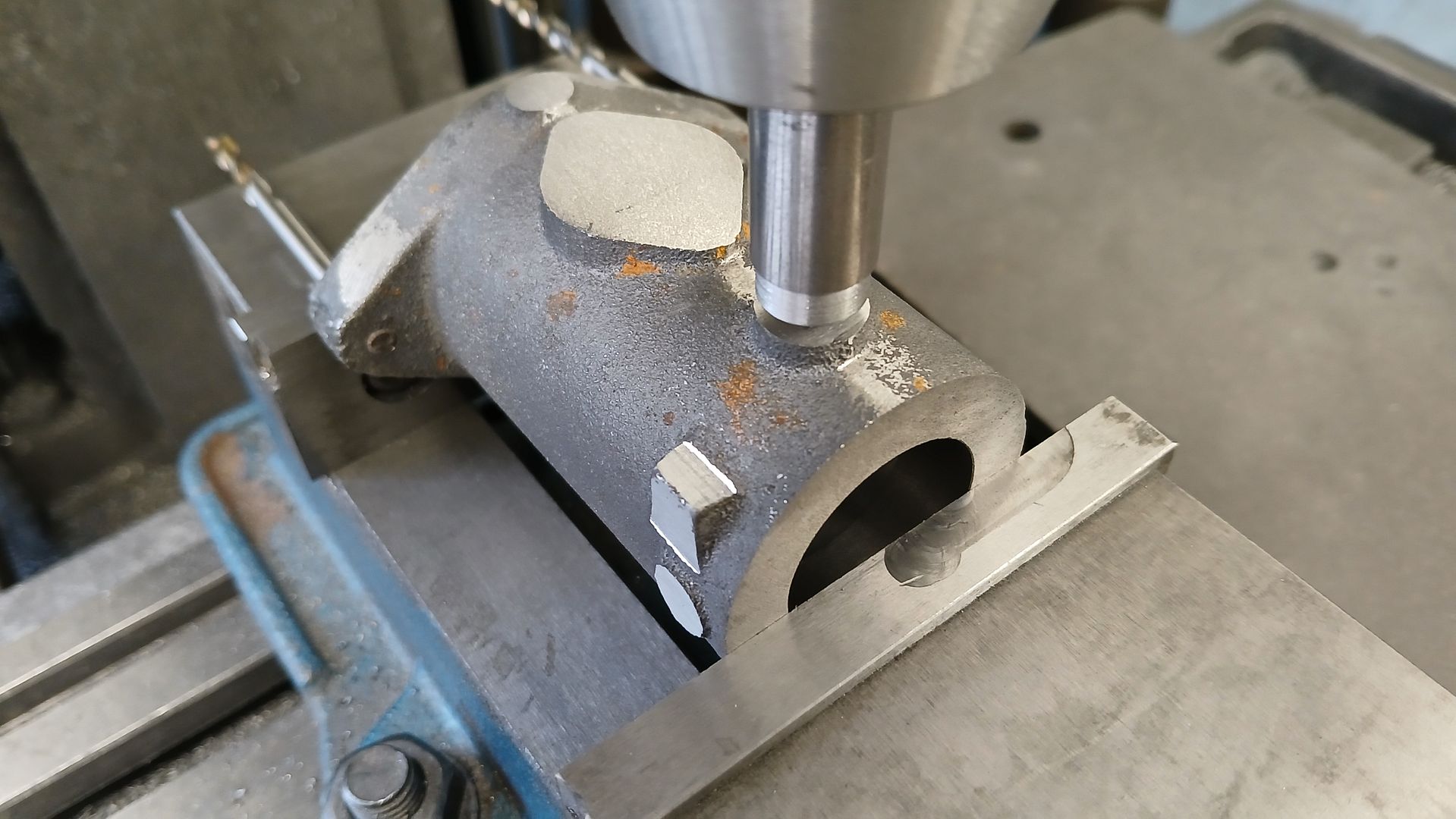
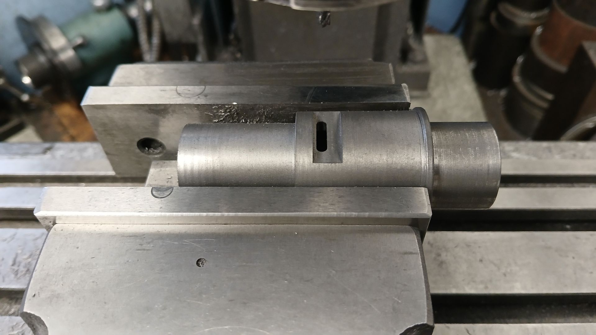
                  With both ends machined it was easy to hold in the vice and mill the various bosses down to height

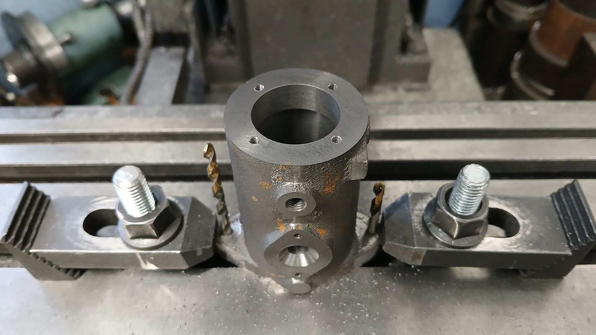
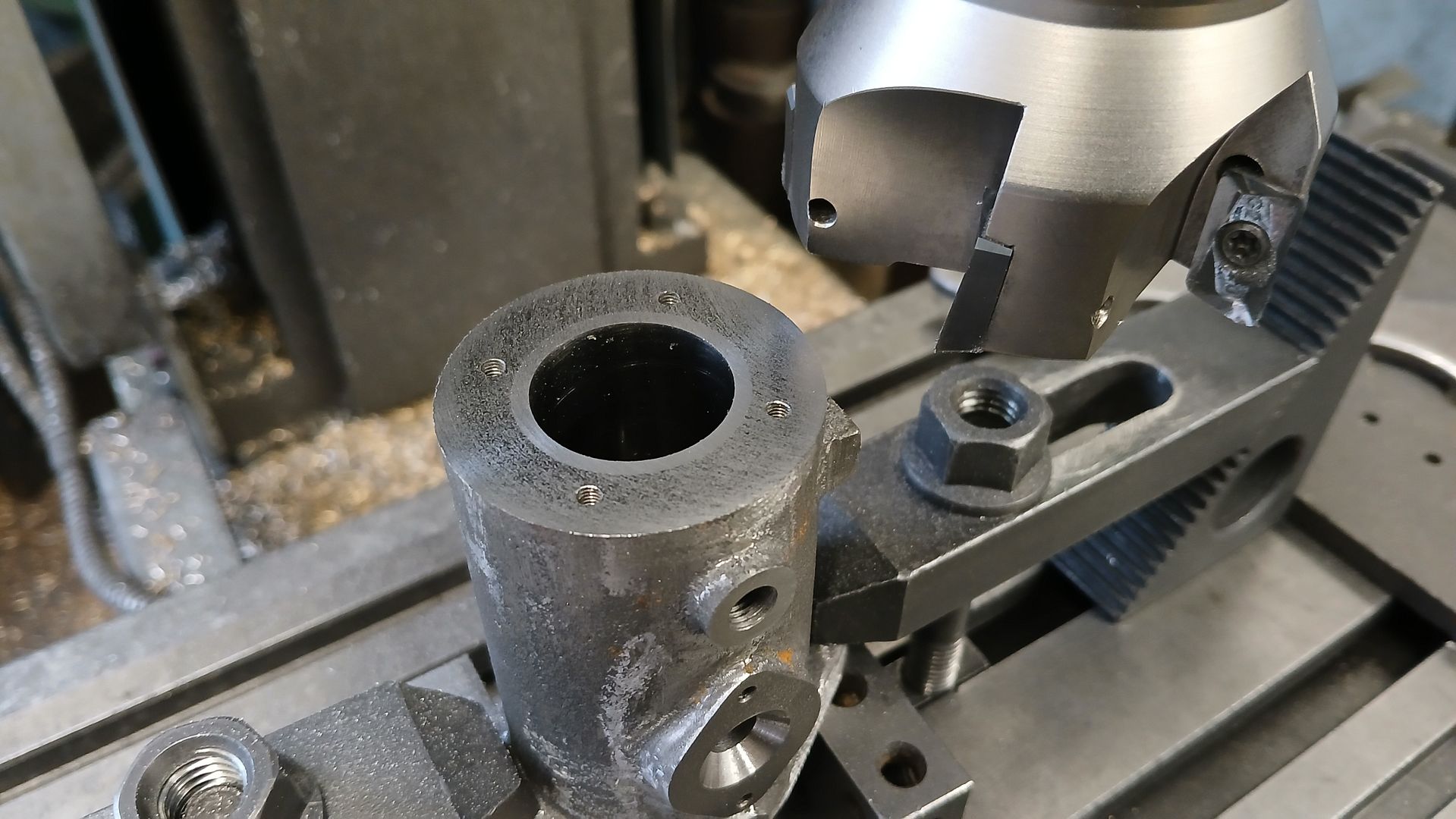
                  The middle of the two water connections was located by holding a similar diameter rod in the chuck and moving the mill’s table until the position looked right. Then swapped the rod for spot drill, tapping drill and tapped M6 x 0.75. Though 1/4 x 40 would suit if using 1/4″ pipe. The other holes will be done once the liner is in place as they pass through it and the cylinder

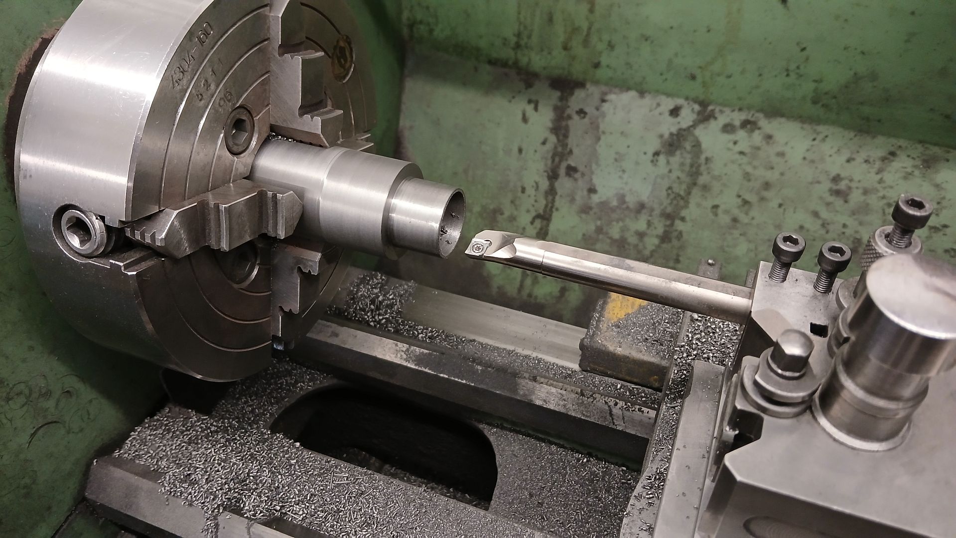
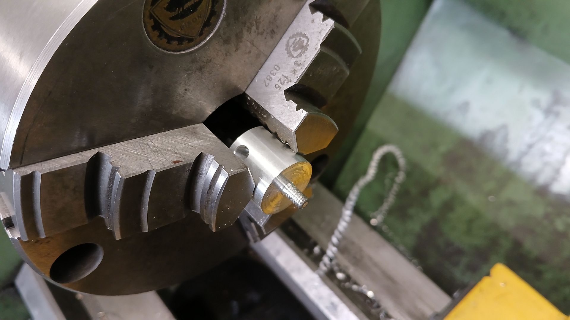
                  I then made a start on the liner, first roughing it down to 1mm over diameter which gave me a clean surface to hold while I turned the spigot that locates in the base.

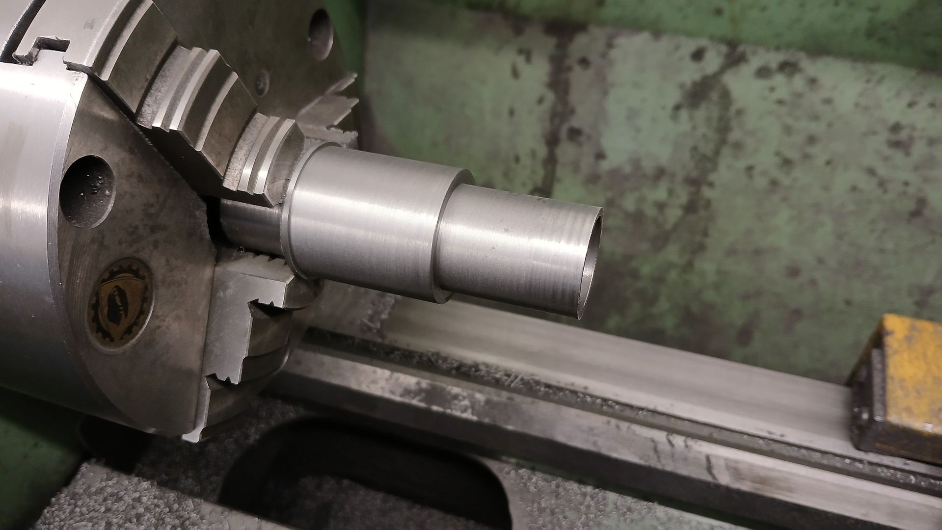
                  At the same setting I bored the liner out to the required 22mm diameter.

                  Then turned it round and did the 26, 33 and 35mm diameters using the cylinder to gauge the fits

                  #767089
                  JasonB
                  Moderator
                    @jasonb

                    Homopractilious has once again been spotted in his natural environment so some more progress.
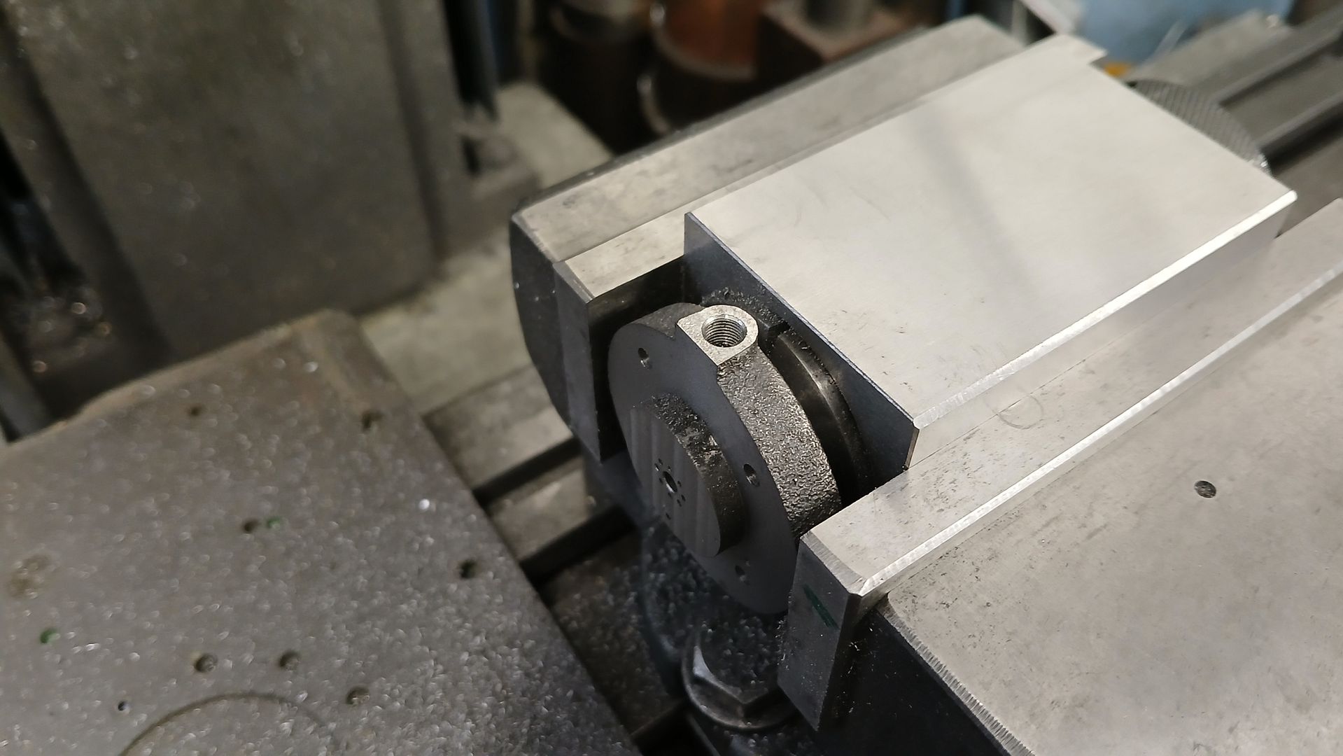
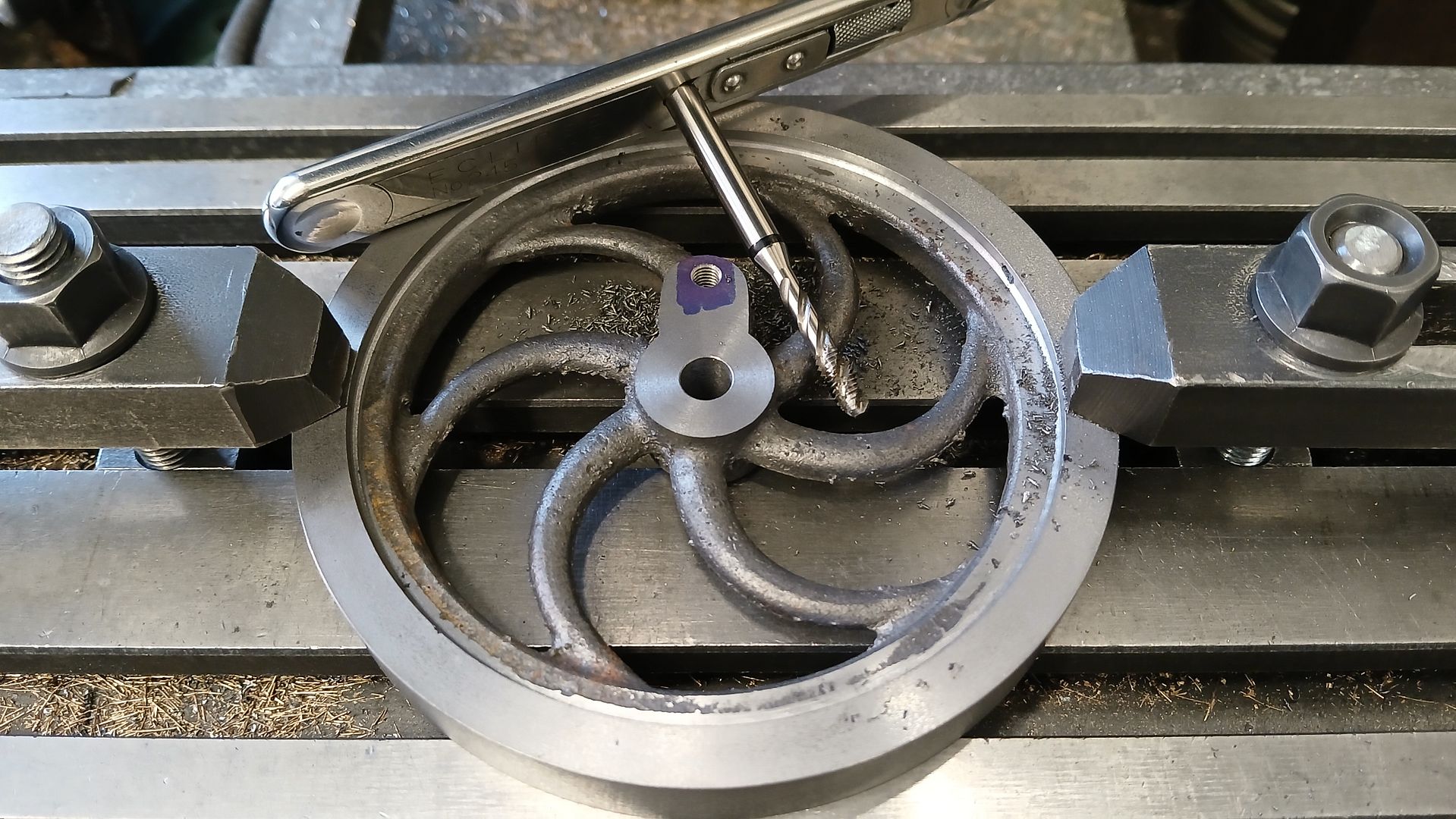
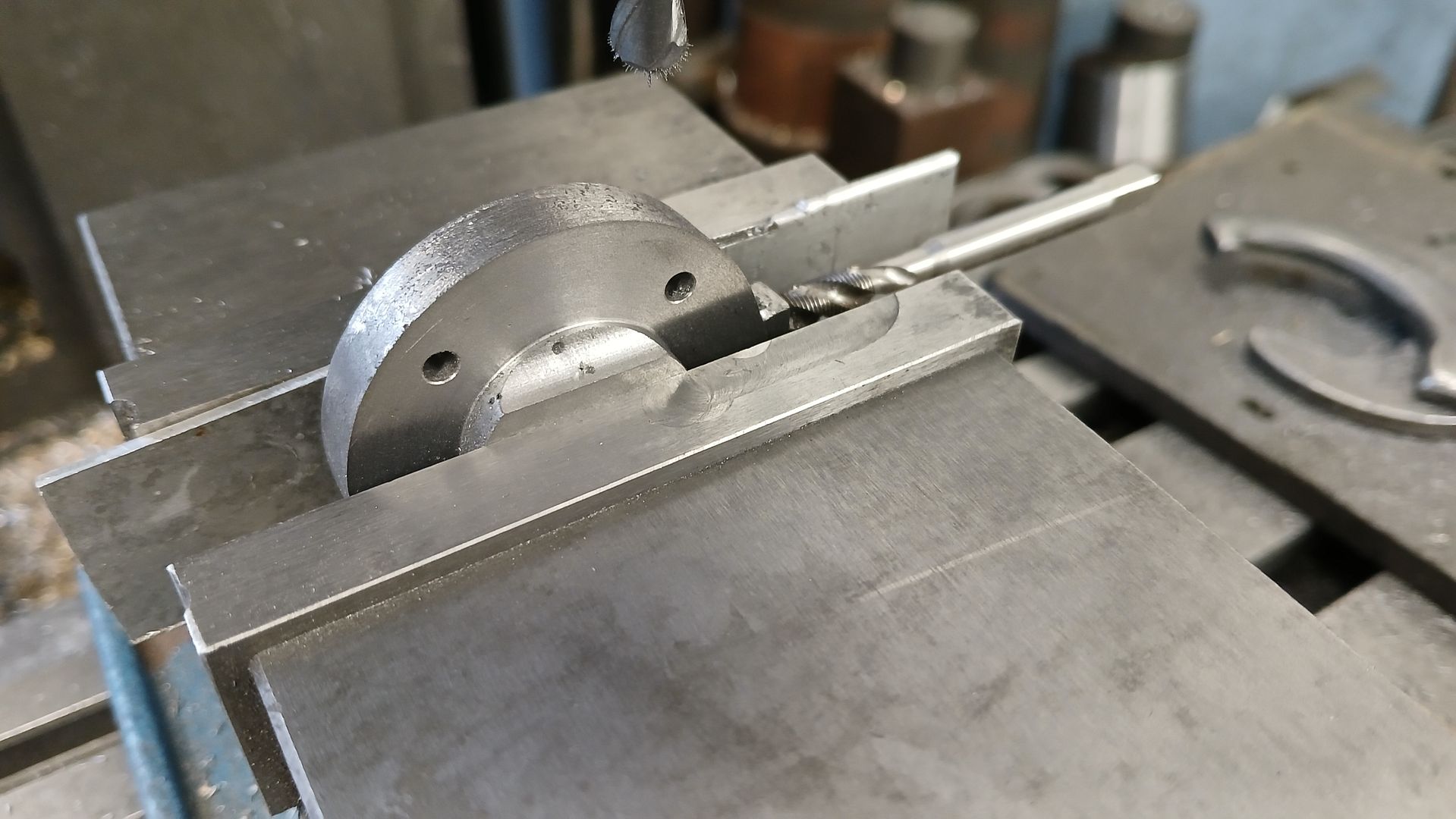
                    Firstly the crank side flywheel was drilled and tapped M5 for the crank pin at 20mm throw. The Blue sharpie wa sjust to check positions and whether an M5 thread would come a bit close to the edge and mean an M4 would have been needed, the actual hole was positioned with the DRO

                    The exit of the hole was lightly spotfaced for a lock nut to bear against but not too deep as the spokes are quite a thin section.

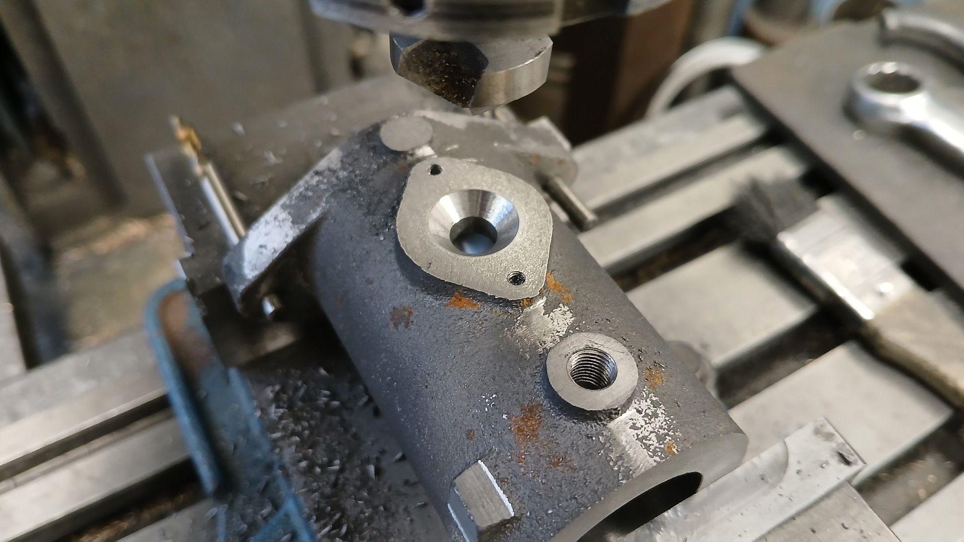
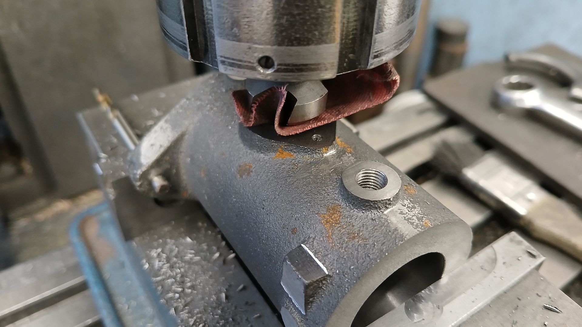
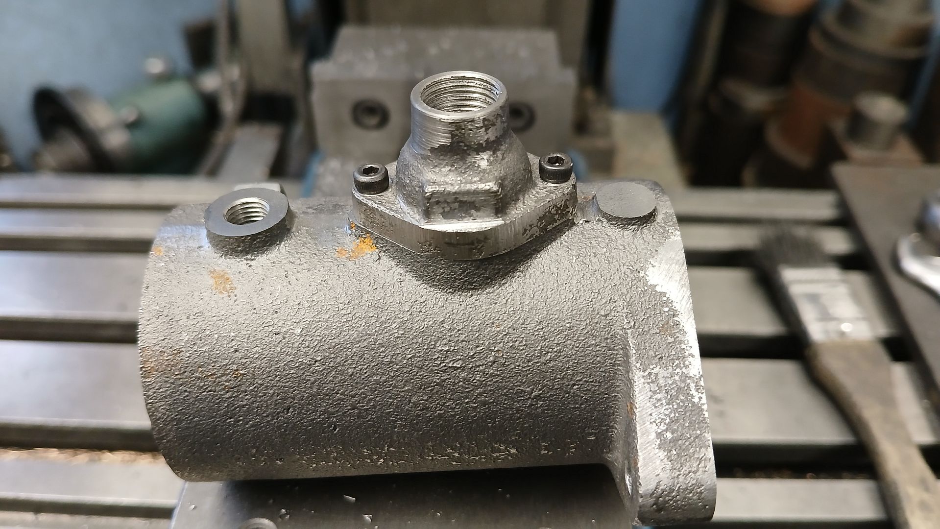
                    The exhaust flange mounting holes in the cylinder were drilled and tapped M2.5 x 4mm deep as any more will risk breaking into the water space. The exhaust passage was then drilled 7mm and a CSK bit used to cut the seat for the ball bearing valve.

                    A nice smooth surface was achieved with a bit of 180G emery spun under the CSK bit

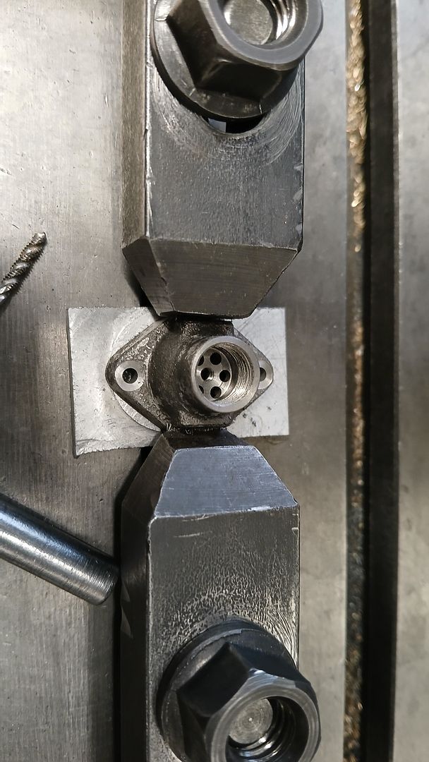
                    As Graham’s prototype used quite a large ball as the valve and it need room to jump about only the minimum amount was skimmed off the bottom of the exhaust cap, a 2.1mm hole drilled right through and then a 13mm x 7mm deep cavity formed by a combination of plunge cuts with various milling cutters and finally boring to size.

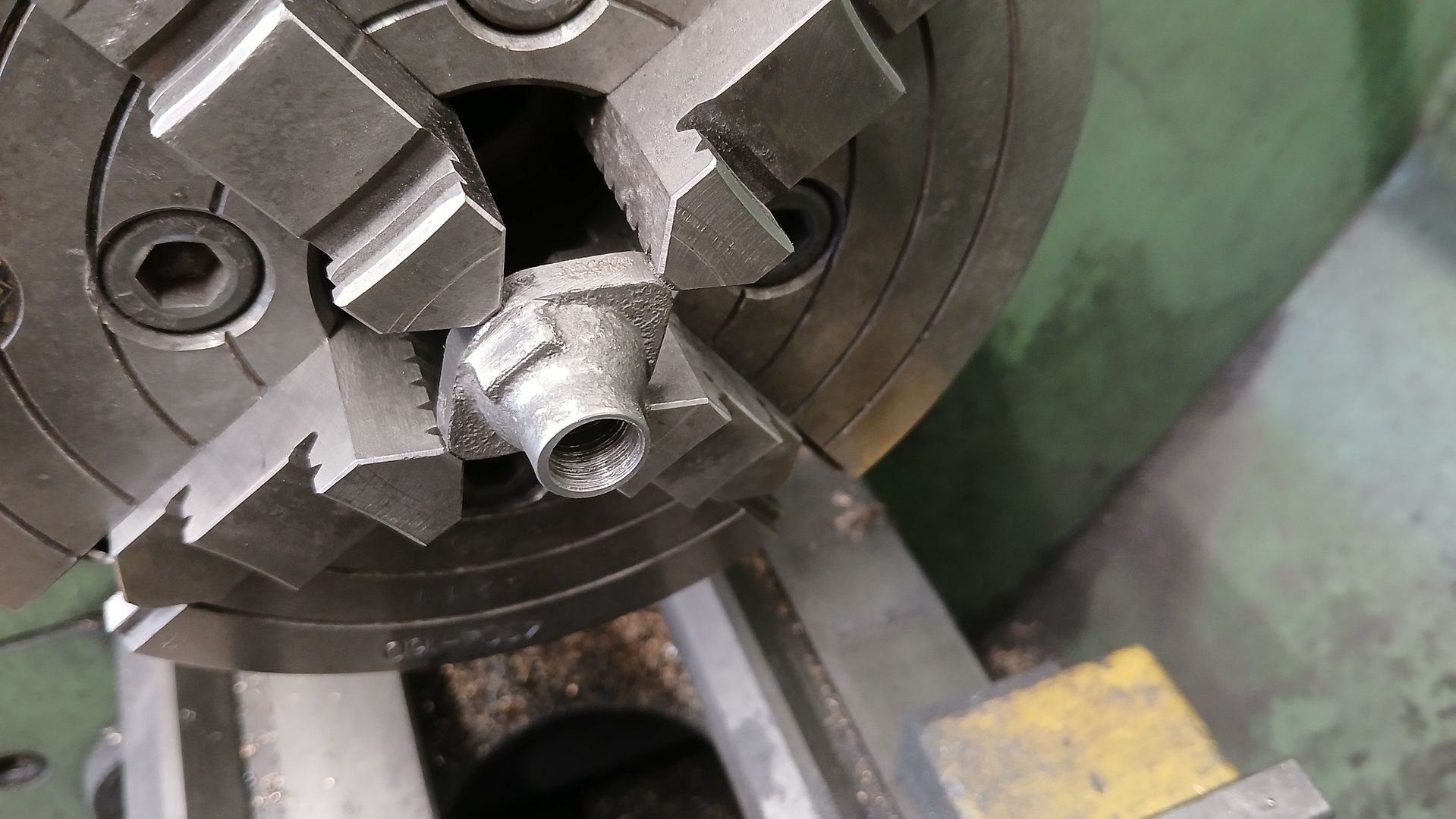
                    Turned the other way around in the chuck, the 2.1mm hole was clocked true and after a light facing cut was drilled and tapped 8mm deep for a G1/8 thread that can take an exhaust pipe.

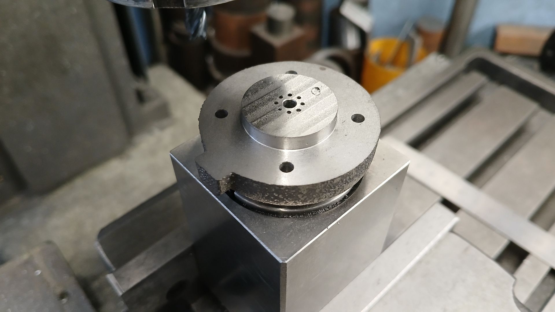
                    Over to the mill and centred up the two mounting holes were drilled & spot faced, a pattern of six equally spaced holes for the exhaust gasses drilled and the last job was to tap the central hole M2.5 for a screw to adjust the amount of ball lift. This is similar to how some of these engines were governed as the governor limited the lift of the flap valve. No governor on this early one though.

                    These CNC and 3D printed patterns come out quite well with mating profiles being quite a good match, just a little fettling and it will be the fit I want.

                    #767091
                    JasonB
                    Moderator
                      @jasonb

                      This is Graham’s prototype running on propane with spark ignition. It also runs on hot tube ignition but has prooved a bit difficult to get the size of the hot tube small enough to look in scale.

                      Being even more practical than me you may notice his use of a bit of hacksaw blade to retain the exhaust’s ball valve and out of site is the ignition contact which is simply clipping the wire in the right position so it grounds on the conrod as that come round. Don’t think he used the clothes peg gas regulator on this run. And yest it is running on the Kitchen table

                      #767094
                      Diogenes
                      Participant
                        @diogenes

                        Must be hard to get a small tube to hold it’s heat – just out of interest, will a glow-plug self-sustain on gas?

                        Those castings do look nice..

                        #767100
                        JasonB
                        Moderator
                          @jasonb

                          It is not helped by the fact the hot tube on this one fits into the side so you either need a bend or a joint, easier if it came out the top of the cylinder or head.

                          An RC “nitro” type Glow plug won’t work with propane or petrol it needs the methanol vapor which acts as a catalyst on the platinum wire to keep it glowing. Most model engines that make use of that type of glow plug have  apermanent supply to keep the plug glowing.

                          Big blow torch will also keep a hot tube hot.

                          ideal running

                        Viewing 11 posts - 1 through 11 (of 11 total)
                        • Please log in to reply to this topic. Registering is free and easy using the links on the menu at the top of this page.

                        Advert

                        Latest Replies

                        Home Forums I/C Engines Topics

                        Viewing 25 topics - 1 through 25 (of 25 total)
                        Viewing 25 topics - 1 through 25 (of 25 total)

                        View full reply list.

                        Advert

                        Newsletter Sign-up