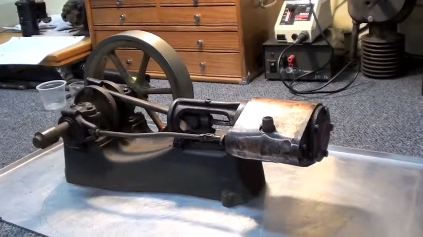
Half Scale 1/4HP A J Weed Engine
Half Scale 1/4HP A J Weed Engine
- This topic has 13 replies, 4 voices, and was last updated 14 April 2025 at 19:15 by
 JasonB.
- Please log in to reply to this topic. Registering is free and easy using the links on the menu at the top of this page.
Latest Replies
-
- Topic
- Voices
- Last Post
-
-
New ELS-fitted Lathes from Amadeal
Started by:
Neil Wyatt
in: CNC machines, Home builds, Conversions, ELS, automation, software, etc tools
- 5
-
16 April 2025 at 01:14
Pete.
-
Metric Thread Cutting Without Conversion Wheel
Started by:
Nigel Graham 2
in: Hints And Tips for model engineers
- 2
-
15 April 2025 at 23:53
halfnut
-
Pipe Unions, Fittings, Standard Dimensions, CAD
Started by:
MEinThailand
in: CAD – Technical drawing & design
- 8
-
15 April 2025 at 23:14
MEinThailand
-
Generator size for vfd controlled 3 phase 5.5 kw motor
1
2
Started by:
PutneyChap
in: Electronics in the Workshop
- 10
-
15 April 2025 at 22:55
Stuart Smith 5
-
Air source heat pumps
1
2
Started by:
Plasma
in: The Tea Room
- 21
-
15 April 2025 at 22:42
Plasma
-
What Did You Do Today 2025
1
2
3
4
Started by:
JasonB
in: The Tea Room
- 24
-
15 April 2025 at 21:52
Nigel Graham 2
-
Acceptable feed screw backlash
Started by:
david newman 9
in: Hints And Tips for model engineers
- 9
-
15 April 2025 at 20:31
old mart
-
Stuart Twin Victoria (Princess Royal) Mill Engine
1
2
…
48
49
Started by:
Dr_GMJN
in: Work In Progress and completed items
- 32
-
15 April 2025 at 18:28
JasonB
-
Building Bernard Tekippe’s Precision Regulator
Started by:
Chris Raynerd 2
in: Clocks and Scientific Instruments
- 8
-
15 April 2025 at 16:49
Chris Raynerd 2
-
Amadeal VM25L Uneven Motor Brush Wear
Started by:
Richard Kirkman 1
in: Help and Assistance! (Offered or Wanted)
- 6
-
15 April 2025 at 13:03
Richard Kirkman 1
-
1965 Colchester Chipmaster
Started by:
andyplant
in: Introduce Yourself – New members start here!
- 4
-
15 April 2025 at 11:01
Emgee
-
Abrasive tape/paper recommendations please
Started by:
Richard Evans 2
in: General Questions
- 7
-
15 April 2025 at 10:39
JasonB
-
Machine tool transport
Started by:
Robin Gibson
in: The Tea Room
- 9
-
15 April 2025 at 03:46
Pete.
-
24cc DIESEL ENGINE FROM SOLID
Started by:
dean clarke 2
in: I/C Engines
- 9
-
15 April 2025 at 00:10
dean clarke 2
-
Problem getting the right parameters on a VFD
Started by:
Robert Graham
in: Electronics in the Workshop
- 8
-
14 April 2025 at 20:14
Robert Graham
-
Myford Super 7 questions
Started by:
davp1971
in: Help and Assistance! (Offered or Wanted)
- 13
-
14 April 2025 at 20:11
davp1971
-
Half Scale 1/4HP A J Weed Engine
Started by:
JasonB
in: Stationary engines
- 4
-
14 April 2025 at 19:15
JasonB
-
Hemingway Myford Top Slide Question
Started by:
Nicholas Hill
in: General Questions
- 8
-
14 April 2025 at 18:40
Michael Gilligan
-
Ruston proctor tractor part built.
Started by:
doublechimny74
in: Introduce Yourself – New members start here!
- 3
-
14 April 2025 at 17:56
doublechimny74
-
Sieg SX2P – DRO, power feeds, CNC? What first?
1
2
Started by:
nevillet
in: CNC machines, Home builds, Conversions, ELS, automation, software, etc tools
- 13
-
14 April 2025 at 10:28
John Haine
-
Diamond grinder wheels – Review
Started by:
peterhod
in: Workshop Tools and Tooling
- 5
-
14 April 2025 at 10:27
peterhod
-
Freecad external threads
Started by:
vintagengineer
in: CAD – Technical drawing & design
- 8
-
14 April 2025 at 10:05
SillyOldDuffer
-
N Devon Model Engineers, is this the end?
Started by:
Engine Builder
in: Model engineering club news
- 11
-
13 April 2025 at 22:28
Chris Crew
-
1200+ magazines to read!
Started by:
beeza650
in: Model Engineer.
- 6
-
13 April 2025 at 19:52
beeza650
-
Shop Tips
Started by:
Vic
in: The Tea Room
- 2
-
13 April 2025 at 19:19
Vic
-
New ELS-fitted Lathes from Amadeal
Latest Issue
Newsletter Sign-up
Latest Replies
- New ELS-fitted Lathes from Amadeal
- Metric Thread Cutting Without Conversion Wheel
- Pipe Unions, Fittings, Standard Dimensions, CAD
- Generator size for vfd controlled 3 phase 5.5 kw motor
- Air source heat pumps
- What Did You Do Today 2025
- Acceptable feed screw backlash
- Stuart Twin Victoria (Princess Royal) Mill Engine
- Building Bernard Tekippe’s Precision Regulator
- Amadeal VM25L Uneven Motor Brush Wear

