Had Another Go
Had Another Go
Home › Forums › CAD – Technical drawing & design › Had Another Go
- This topic has 358 replies, 22 voices, and was last updated 19 February 2025 at 22:51 by
Nigel Graham 2.
-
AuthorPosts
-
22 January 2025 at 10:21 #778998
David Jupp
Participant@davidjupp51506Nigel,
The ‘spare piece’ that you can’t delete.
If in part workspace – right click on the spare bit in the workspace, choose ‘show feature in explorer’ – this will highlight it in the Design Explorer – you can then delete it. You may have to repeat if the spare pieces is actually several features.
If in assembly workspace, simply right click on the spare piece and select Delete.
22 January 2025 at 10:29 #779003 Julie AnnParticipant@julieann
I run Alibre Design Expert, so have a mirror function in the assembly space. But I don’t recall having ever used it.
If the intent is to make one chassis rail that will work for both sides the original rail and the mirror need to be identical, and to have rotational symmetry. It seems unlikely that the chassis channels will be mirror images right down to every hole and bracket. The rails need to have rotational symmetry as any hole or feature not on the centre line will be off when the part is rotated to the other side. It would be sensible to model the two chassis rails as seperate parts, left and right.
Julie
22 January 2025 at 11:25 #779015SillyOldDuffer
Moderator@sillyolddufferI run Alibre Design Expert, so have a mirror function in the assembly space. But I don’t recall having ever used it.
…
Julie
Quite so! Mirroring an assembly is an advanced operation, rarely used I imagine. Wanting to mirror an assembly causes a red light to flash in my mind! The requirement could be bad. Might be clever and legitimate, or a misunderstanding. If a misunderstanding, don’t mirror assemblies!!!
The most common reason for mirroring an assembly I guess is to create Left and Right hand versions of the same item. Something like a disc brake assembly for a car. But designers avoid specials: much better to design a brake that’s neutral so it can be fitted to either side.
My guess, which could be completely wrong, is that Nigel wants to mirror his chassis rail. Mirroring parts and sketches is normal and common, but the resulting RH and LH pair are incorporated separately into a single assembly. Though it contains mirrored parts. the assembly isn’t right or left-handed.
Nigel: Learning how to mirror an assembly at this stage of your CAD apprenticeship might be a confusing time-waster. Analogous to bashing one’s brain with matrices at school when they are never needed again…
Which assembly do you want to mirror, and why? The answer may be “don’t”! A different approach might be better.
Dave
22 January 2025 at 11:27 #779020 JasonBModerator@jasonb
Nigel, I have said several times when giving suggestions that mine may not be the same as yours particularly the arrangement of icons at the top that is because I have Alibre Professional.
It’s a bit hard knowing exactly what was pared down to make Atom more affordable and I also have to remember not that you are on V27.
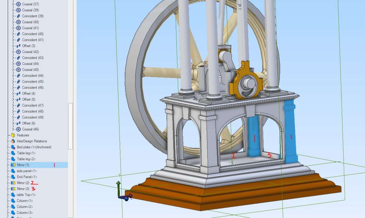
Like Andrew I don’t often mirror in assembly but did actually use it for the current engine as after placing two of the base corner columns the other two were just the same on the other side of the engine. Also down the tree you can see the side and end panels were mirrored. This saves having to apply several constraints to the individual parts had I imported 4 legs and two of each panel.
 22 January 2025 at 11:41 #779026
Nigel Graham 2
Participant@nigelgraham2David –
Thankyou. Found how it was listed in Design Explorer and that I could delete it there.
I certainly agree about Matrices – an extremely specialist area but unfortunately they were part of the standard school mathematics course I took for work purposes, so I had to learn how to “do” basic ones even though not taught anything else about them, including need.
At least CAD tools like Mirror do have obvious meanings and uses… and if their hidden maths uses matrices those stay safely hidden in the box of electronics.
.
Julie –
Ah, well, that’s the difference. Alibre Atom is a bit more limited and its Assembly functions do not include Mirror.
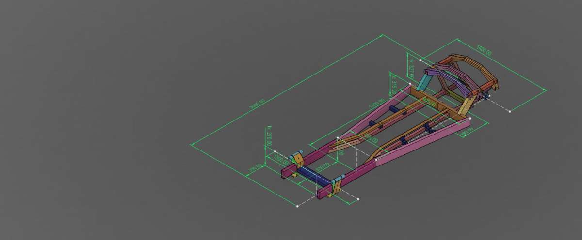
No, the side-rails are not identical to the last bolt-hole, but I cannot design the thing to that level of detail and much of it is largely already there.
It’s only now, to design and make the engine and transmission-gearing, that I need half-decent workshop drawings. Unfortunately that machinery will occupy the area I can’t draw properly in CAD, and that area might be the wrong shape anyway!
The two bits of steel are the same despite rather rough-and-ready fabrication methods. I placed some primary bolt-holes by clamping the rails back to back, but with it now assembled, drill through from the components I am fitting.
The chassis has plenty of spare holes now, by the many changes in inching slowly towards building the vehicle.
The horrible thought, from the one useful works photograph, is that I should have swan-necked the chassis in the very short area between the front of the machinery space, and the rearward front spring mountings – a displacement of over an inch sideways in about four length. (20.6º)
That would need completely new longitudinal members, probably need new boiler mounting brackets. It could give give major difficulties for the steering-column and gearbox, right in that transition area. (Ackermann steering)
The two pairs of joints would need hefty filler and cover-plates bolted or rivetted on. Possibly the full-size method impossible to determine from the surviving photographs – and every Hindley wagon seems different from its brothers in details anyway.
On the other hand it seems more true to original, relatively easy and quick to do, allow correcting one or two other mistakes, and facilitate putting the road-gears all within the chassis, as correct, in a nicely-rectangular area.
A further option is an all-square layout, basically two rectangular frames end-to-end with the smokebox forming the front cross-member. Simple and mainly hidden detail, but possibly not very structurally sound and prototypical.
Any angled form would just as hard for me to draw in CAD than the present version.
The transmission seems to have been two-speed on the larger “Standard” wagons at least. Those were undertypes with the machinery all mounted from the rear axle, and the driver had to dismount to change gear. I can’t work out how the ‘Light Delivery Van’ mid-chassis gearing was arranged. All I know is that the tapered chassis I have made, has unwittingly hampered replicating the transmission reasonably faithfully in miniature. I did not receive the single crucial photograph giving hints, until well after completing it.
22 January 2025 at 12:26 #779028Nick Wheeler
Participant@nickwheelerI run Alibre Design Expert, so have a mirror function in the assembly space. But I don’t recall having ever used it.
…
Julie
Quite so! Mirroring an assembly is an advanced operation, rarely used I imagine. Wanting to mirror an assembly causes a red light to flash in my mind! The requirement could be bad. Might be clever and legitimate, or a misunderstanding. If a misunderstanding, don’t mirror assemblies!!!
The most common reason for mirroring an assembly I guess is to create Left and Right hand versions of the same item. Something like a disc brake assembly for a car. But designers avoid specials: much better to design a brake that’s neutral so it can be fitted to either side.
My guess, which could be completely wrong, is that Nigel wants to mirror his chassis rail. Mirroring parts and sketches is normal and common, but the resulting RH and LH pair are incorporated separately into a single assembly. Though it contains mirrored parts. the assembly isn’t right or left-handed.
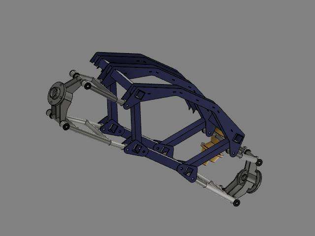
Meanwhile, everything here(and the rest of the chassis)

was designed on one side, and then mirrored around the centre line. You can see the join in the rear crossmember:

All of the flat parts are copies of the first part and are intended to be laser cut to save time, work and be self-jigging because slot and tab construction is effectively free. The wishbones and hub carriers are intended to be built in the same jigs, although the caliper brackets will need to be handed.
Although it looks complete, it’s mostly guesswork for a general arrangement and ‘what else do need to know?’ For example, the rear suspension geometry is atrocious.
Mirroring the parts saves so much work!
22 January 2025 at 12:35 #779037Nigel Graham 2
Participant@nigelgraham2Nick – you are right in what I had wanted to do. My lorry’s chassis is simple (well, in physical form it is) and symmetrical in all but small details. Also I had not realised the Mirror tool is such a trap for a novice like me. Best avoided then…. along with Sweep.
……
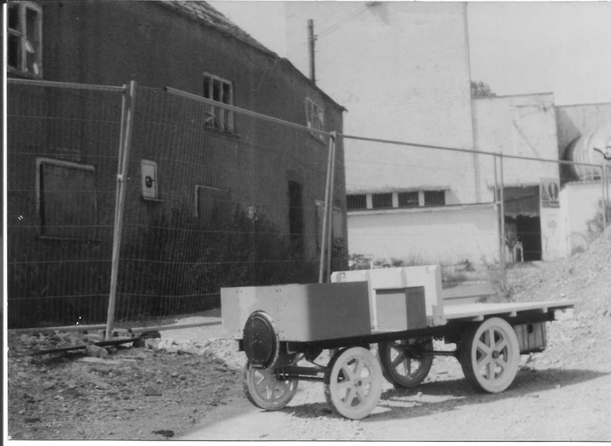
Here she is, some 18 years ago and not much advanced since (two house moves in that time don’t help), posing outside the ruins of her ancestral home in the Dorset village of Bourton. The building on the left is recogniseable in some of the advertising photographs taken almost a century earlier. I had the boiler and some other parts with me, but left them in the car. Sorry about the low-quality scan of the proper photograph.
 22 January 2025 at 13:23 #779048
Nick Wheeler
Participant@nickwheelerNick – you are right in what I had wanted to do. My lorry’s chassis is simple (well, in physical form it is) and symmetrical in all but small details. Also I had not realised the Mirror tool is such a trap for a novice like me. Best avoided then…. along with Sweep.
This is where I disagree with many of the other posters here, and suspect is some of the cause of your problems. Many of the CAD oddities that bamboozle new users are what make operations like assemblies or copies(mirroring is a specific type of copy) both feasible and predictable.
For instance; my main chassis rails are to be 100×40 steel box, and making the two separate parts meet properly at the bulkhead took ages due to the angles involved.
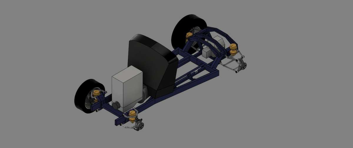
WhenIf I ever get around to building the car, I will sweep a 100x40x3mm thick profile along the outside line and split them at the angle with a plane through three of the corners to make the separate pieces. I’ll do the rear kickups by using the crossmember to subtract the desired cutout, instead of working it out for myself.Here’s the chassis with the sketch that drives the dimensions I know, like the wheelbase and trackwidth, axle centre heights(different wheel sizes), width of the body at the bulkheads and their distance apart etc. The relevant points were then projected into whatever part I was working on:

If those examples seem familiar to you, perhaps you’ll better understand the reasoning behind many of my previous suggestions….
22 January 2025 at 15:08 #779058Nigel Graham 2
Participant@nigelgraham2That is one very ambitious and complex project, Nick!
Oh, of course I can see why CAD, or at least its higher-grade editions, offers these more advanced tools like Mirror and Sweep. They make the system so much more efficient and powerful, for those able to use them to their full advantage.
They are only bamboozling oddities to those who can’t understand them…. like me.
Your full-size car is, and has to be, far, far more complex than my one-third size replica of an Edwardian lorry that probably cruised at a heady 5mph. Any more would have shaken the crew to bits, riding above those tread-free steel tyres. I don’t need worry about complicated steering geometry, high-strength / low-weight frame members at compound angles to handle high forces in strange directions, and so on. Mine has a flat chassis holding a low-powered steam-engine, controls in rather inconvenient locations, undamped leaf-springs and steering described as “Ackermann” but apparently free of camber, castor and toe-in. (I have given it an adjustable track-rod and slight castor angle!).
Consequently designing your car demands a skill at using CAD far, far higher than my project needs and I could hope to achieve. Julie’s single-crank compound traction-engine is somewhere between these in mechanical complexity, Jason’s engine is a lot simpler but full of fancy bits; but all three of you are of comparably advanced CAD skills.
By contrast my wagon should be easy to model to considerable detail in Alibre Atom 3D. You experts would do that in an evening or two. I don’t believe I’ll ever manage that.
So although I might not always understand the technical reasoning for your ways of using CAD, I can at least appreciate that you found it easy to learn to use to full advantage for very high-grade work in the most efficient way.
22 January 2025 at 18:15 #779087Nick Wheeler
Participant@nickwheelerIt certainly wasn’t a quick or easy process, even after ditching Turbocad. I’m still finding things I don’t know how to model. If I had to do this on paper I’d still be struggling how to mock up the wheels. Doing it without a good idea of how it all fits together would mean a huge amount of wasted time, work and materials.
What you’re seeing is the fourth iteration, and lots of vital information is missing: accurate details of the engine, gearbox and differential, working rear suspension geometry, a final decision on whether the mooted Hydrogas displacers are viable or to break the piggy bank for coilovers, as it currently ‘exists’ the crank pulley wants to go where the steering rack must fit(which is why there isn’t one shown), I don’t know if the throttle body needs to be moved from the back to the front of the inlet manifold, there isn’t room in the k-member for an exhaust and I really want the lower tube to be one piece from the rear suspension when it would fit better level with the top of the frame, and so on.
All of those need a physical mock up of the body, wings, wheels, bonnet, grill shell and existing frame to determine if I like the look(important for a hot rod) and provide actual measurements instead of a mix of informed and wild-arsed guesses. Then it will be time to do the whole lot again from scratch using what I’ve learnt so far.
22 January 2025 at 19:04 #779104Nigel Graham 2
Participant@nigelgraham2Re-measuring the chassis and using various clamps and straight-edges to see where things will lie, suggests I don’t need modify it, which is a relief! Though if I do need modify it, I could also see a simple way to do so without making awkward angly bits.
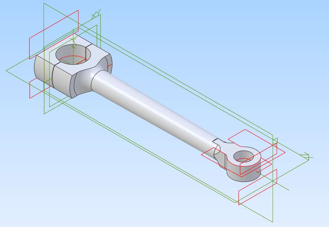
The awkward bit about modelling this connecting-rod was not an Alibre-driving problem but how to develop the small-end. I had made them but at 4-inch ctrs, too short. This one is of 6-inch ctrs. I think a slightly greater taper, to a smaller neck at the small end will make it a bit less ecclesiastical-architecture and more engineering, and give a bit more clearance inside the cross-head.
 22 January 2025 at 19:14 #779108
Nick Wheeler
Participant@nickwheelerThe taper is an excellent time to try revolving around the centre axis. Then reflatten the small end for the piston by cutting with the sketch you’ve already used to create it.
Although you could revolve the big end and beam from one sketch, then flatten the ends with the holes from another. That would be easy if modelling the conrod from an existing crank pin and piston/bore….
22 January 2025 at 20:58 #779141Nigel Graham 2
Participant@nigelgraham2Thankyou! I did indeed generate it by Revolve.
I think the best way to make connecting-rods like this, is analogous: turn it from round bar. It can be made from rectangular stock but that can create a heck of a lot of interrupted cutting, not good on an elderly lathe with screw-on chucks.
I had to create a wee gap between the two sections to find and remove a lot of Overlap errors and make sure it was two separate blocks working in concert. I formed the small-end from a rectangular “block” so it became an over-size copy of the big-end; cut the two flats than puzzled how to create the extrude-cut outline visible on the image above. Quite a lot of experimental geometry on the Sketch, and trying to think what would happen! I made a spare file copy first in case this stage went all horribly wrong.
I’ve omitted the cap-bolt holes, but also using the two turning centre-drillings. The small-end one becomes an oil-hole for the bush and pin. The big-end one becomes drilled and tapped for a small brass grub-screw that stops the half-brasses rotating. As the finished engine is boxed in I’ve exploited it being vertical so that surplus oil on the guide-bars can be picked up by channels in the cross-head nose, to lubricate the small-end. Oil running down the connecting-rod can be collected by a small hole in the big-end shoulder to find the bearing. The prototype was splash-lubricated but I’m inclined to rely more on manual oiling on this engine, possibly by a simple hand-pump taking oil from the sump, used at intervals.
…..
Trying to fit all the auxiliaries around a car shows with ordinary commercially-made ones! I think the car manufacturers do still use mock-ups in various forms, though obviously now must use very sophisticated CAD packages with powerful rendering functions.
There must be many chains of consequences similar to the pulley / steering-rack conflict Do you produce various “editions” of each CAD model to determine questions like this?
Are you able to obtain dimensioned outline drawings for any of the purchased components, as you can for with standard electric motors? They might be in print form so would need scanning to be useable in CAD but information like that would be very helpful. I don’t know if such drawings are available already in digital form; possibly not, for commercial-sensitivity reasons.
22 January 2025 at 21:36 #779156 Julie AnnParticipant@julieann
In the example given by Nick mirroring clearly works as the parts are flat and identical, they look the same from left or right. That is not true of the chassis rails.
Although it is not obvious from my assembly all parts are completely designed. The assembly is primarily to ensure that parts fit together, holes align and there are no interferences when the engine is rotated. That is the real power of an assembly.
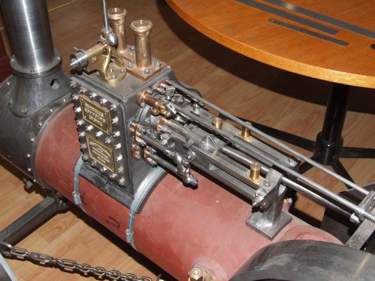
I make a 2D print from a 3D part, make the part to print and expect everything to fit together without adjustment. That was true of the cylinder, piston rods, glands and slide bars – no shims needed:

The above is not intended to discourage Nigel, but to illustrate the power of 3D CAD and assemblies and hence why I think it is worth persevering with.
I still make mistakes in Alibre, or get into a situation when trying to modify a part that it is easier to bin the part and start afresh.
Julie
22 January 2025 at 23:45 #779193Nick Wheeler
Participant@nickwheelerThere must be many chains of consequences similar to the pulley / steering-rack conflict Do you produce various “editions” of each CAD model to determine questions like this?
Are you able to obtain dimensioned outline drawings for any of the purchased components, as you can for with standard electric motors? They might be in print form so would need scanning to be useable in CAD but information like that would be very helpful. I don’t know if such drawings are available already in digital form; possibly not, for commercial-sensitivity reasons.
I’ve never seen a resource like you mention for engines and gearboxes beyond overall dimensions, and those are all DIY efforts with little consistency of what’s included or where they measure. Scans of 2D plans don’t translate very well, although they can be useful for modelling odd shapes. Proper 3D scans are much better, and the tools for doing that are almost affordable. It occurs to me that I might be able to borrow one for the cost of a couple of Toblerones.
The ‘mock up engine’ you see here comes from me crawling under a Metro and measuring the length, height and width with little precision. I didn’t get the crank centre height which would help, as my WAG puts it too low. The gearbox and diff are similar, but based on internet crawls for rough dimensions. That’s why they’re just floating in guessed positions. It doesn’t help that I ‘m using an odd mix of MGF engine, BMW gearbox and Freelander diff!
There’s no need for different editions when the components are placed by parametric joints! You note the parameters(in the programme) and change them to get what’s needed. The engine placement here is another WAG; I put it that far forward to keep as much room in the footwell because this is a tiny car. It can go back a bit, and up quite a lot more; either could solve the problem. The rack/position is fixed, and the pulley can’t really change. The engine doesn’t have to be centred in the car either! While I’d like to have a plain bulkhead, it’s not a requirement.
I’m not going to do any more on this until I have a gearbox and diff to measure. The engine is available, but I need to collect it.
23 January 2025 at 00:42 #779197Nigel Graham 2
Participant@nigelgraham2Nick – Impressive project, and a hell of lot of work. I’m certainly interested in its progress!
Julie – For all practical purposes the two side rails on my model wagon are a mirrored pair. Yes, they do have a few holes on one side but not the other, but those are only details – typically holding pipework and the like. So there was no harm from that point of view modelling them in CAD as a handed pair, and omitting minor details like bolt holes. Those could be put on the part drawings. Especially as I built it years ago anyway!
If I was starting again, or at least making new chassis rails as I did briefly think I’d need, then yes I would carefully measure the existing components and record them on proper drawings.
Something like Nick’s car is a very different matter. That is far more complicated with very many critical components, identical pairs, handed pairs and unsymmetrical one-offs; difficult clearances and conflicts, and obviously the vital matter of ensuring the vehicle’s safety as well as performance. He can only approach it with a lot of preliminary, proper designing.
I do need now do some proper (ish) designing because the major part of my project still to go is the most difficult: the engine and gears, and how to install them as they should be.
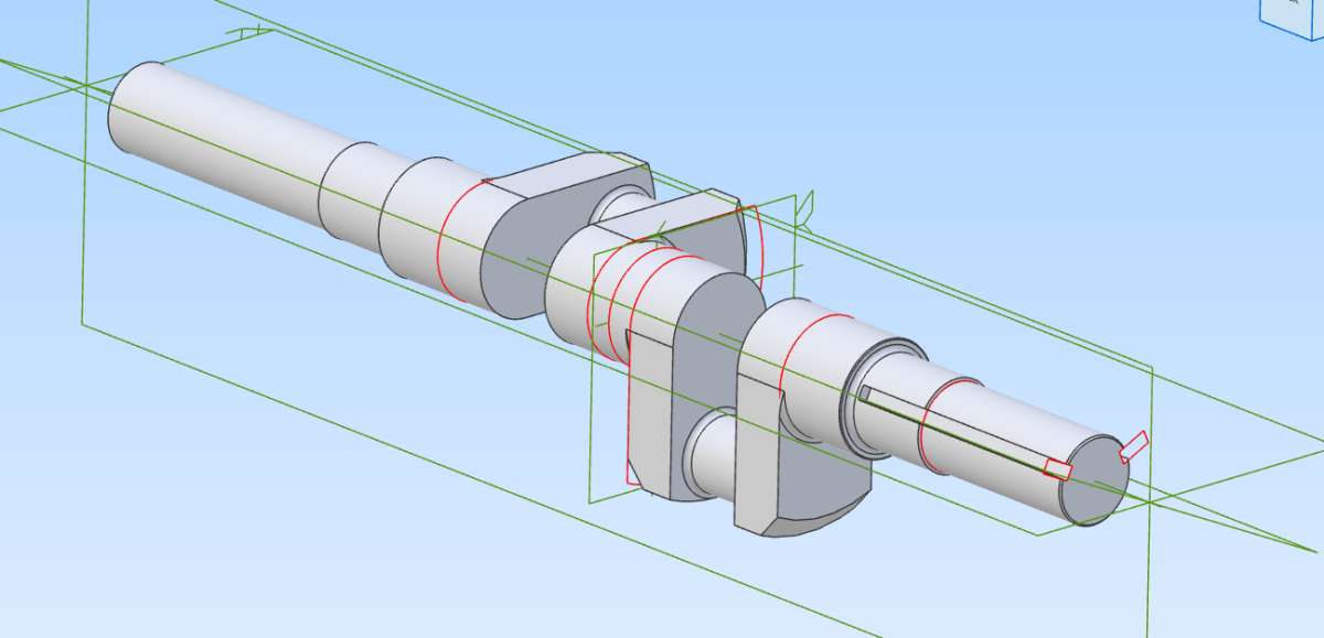
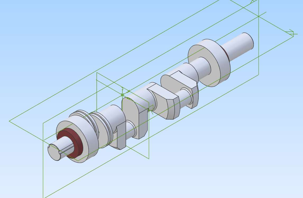
In fact I’ve carried out a bit of surveying and a few hours of CAD modelling this afternoon and evening: the connecting-rod a couple of messages above, and the eccentrics. Accompanying that was devising a sort of basic Reaulaux Diagram on screen to be able to determine the angle of advance hence set out the keyways on the crankshaft. Then work out by inspired guess and trial-and-error how to “cut” them on the crankshaft.
The drawing is not strictly accurate as it puts the keyways through the main bearing seating and oil-seal, but I can do something about that on the shaft’s own Part drawing, if only by an annotation. Then in real life, lift the cutter over the bearing area!


So I do know the advantages of tools like CAD…. just a matter of managing to learn it well enough.
23 January 2025 at 07:10 #779210 JasonBModerator@jasonb
For the Chassis Rails if you wanted to detail all holes etc the time to use Mirror would have been at the initial modeling stage.
Produce one rail, save and call that rail left or Rail right depending on which you drew
You can then Mirror that whole part and “save as” Rail Right/left
You then have a left and right rail that can be detailed but the mirror saved having to draw it twice. Infact you could detail all the shared holes before you make the mirrored copy so less work again.
The two chassis files are then imported into an assembly.
For the conrod I would have done it slightly differently for the small end. I would draw that as a circle and do a mid extrude, then do the tapered rod either by revolve, loft or using extrude with Draft (if Atom has that) Then where the little end meets the rod add a fillet
23 January 2025 at 09:32 #779264David Jupp
Participant@davidjupp51506Nigel,
Re the keyway that extends into the main bearing journal. Looks like the extrude cut used just goes too far. So either edit the depth value OR change the cut into a ‘to geometry’ type and specify the step face on the end of the bearing journal.
Looks like you are definitely managing to model more complex parts.
23 January 2025 at 11:36 #779288Nigel Graham 2
Participant@nigelgraham2Thank you!. No, the keyways do not go too far, but they should not be continuous.
Two are needed on the section beyond the bearing (which I represented simply as a big plain disc), symmetrically placed at about 25º each side of the neighbouring crank. Each of those keys drives an eccentric (the thin discs with the groove round them).
It also needs at least one keyway on the outer end of the shaft.
They should be quite separate, not cut into the bearing seating. Less still where the oil-seal (the brown disc) fits!
I made several attempts but could not see how to represent that properly, so concentrated more on their basic forms and placing.
When I modelled the eccentric I spent some time on geometrical constructions and examining the physical components I am drawing, to see if I could use a single keyway in the shaft and eccentric in such a way that the latter can be handed. So the two eccentrics are identical and simply turning one over would place it in the opposite angular orientation. Obviously, if you could, thousands of steam-engines big and small would have already been made that way in the last couple of centuries! However you approach it, one component needs two of the locating features, and it was always normal to use identical eccentrics and two shaft keyways.
That wasn’t a CAD question, simply one of mechanical design geometry.
…
Jason –
Thank you for clarifying that. I had used Mirror for rings of holes and simple rectangular objects so was lulled into a false sense of security.
However I had never thought depicting two bits of bent channel could have so many ramifications! The discussions over them raised at least three points:
1) Is it possible to reflect a solid entity? Yes but not simply. So this is my not knowing the Mirror tool properly.
2) Could that bent channel be so reflected? Only if the Mirror tool can do it. See 1) above.
3) Assuming it can be as a CAD move, would it be legitimate mechanically though? In this case YES, because the initial object for reflecting has NO holes or other features to make them fully handed. Lay one on the floor and the other, inverted, will stack on top of it. That’s how I tested their equality when I made them, long before drilling holes all over them.
So in a CAD model, if the Mirror tool works on such objects is there any design reason not to use it, before any holes in the webs and flanges? In effect it is an upside-down copy, simulating that stacking to compare the real beams’ shapes. (I’m not asking how the software creates the reflection, only about the result.)
I was trying to model merely two identical lengths of steel formed but not further modified; one turned upside-down and slid sideways!
I realise I do not really understand the Mirror tool and when it can’t be used, but why do people use the engineering to say I can not model that frame by reflection? I appreciate their help, but the original part shows no engineering reason not to; and from the CAD aspect it would plant a central plane for further use.
Those rails also threw up another problem, that of depicting them anyway. It would seem using the Sweep tool is the best way, but unfortunately I cannot understand how.
23 January 2025 at 11:43 #779290David Jupp
Participant@davidjupp51506Nigel, sorry I obviously mis-understood your previous post and the comment on the keyways.
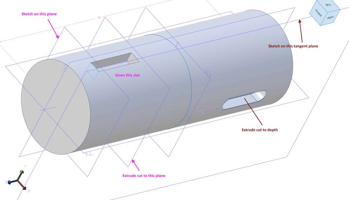
You could use some additional planes (or other existing faces) to place the sketch(es) on for the start of the keyways. You can sketch ‘inside’ a solid – though that may feel odd. A ‘precise section view’ can be helpful.
You can also produce keyways starting with a tangent plane touching the shaft, and cut down into it.
I’ll model a simple shaft with different keyways to illustrate some options.
 23 January 2025 at 11:55 #779296
Nick Wheeler
Participant@nickwheelerFor the Chassis Rails if you wanted to detail all holes etc the time to use Mirror would have been at the initial modelling stage.
Produce one rail, save and call that rail left or Rail right depending on which you drew
You can then Mirror that whole part and “save as” Rail Right/left
You then have a left and right rail that can be detailed but the mirror saved having to draw it twice. In fact you could detail all the shared holes before you make the mirrored copy so less work again.
The two chassis files are then imported into an assembly.
You could work on the side with the most bits attached before the mirror operation, then delete(if you can’t just ignore) any obviously redundant holes when the design is complete. Production parts often have mirrored features so that they can be used for left and right hand-drive. The later you leave mirroring the part, the more efficient it is. It’s better for you too, as the mental effort can be spent on the design rather than keeping track of the parts.
Don’t forget that visibility of incomplete parts can be turned on/off as necessary to save clutter or prevent design clashes.
Our CAD projects are actually at very similar points where the focus should be on getting the major mechanical parts fixed so they’ll actually work. Mine needs better information on the drivetrain, and some proper engineering on the rear suspension geometry; I would be defining the boiler, axle and steering on yours.
Julie’s point about realising that starting again using what you’ve learnt from the previous attempt is also important. It’s slightly easier to do in CAD, because at least you won’t be scrapping expensive materials as well as time and effort.
23 January 2025 at 12:24 #779305 JasonBModerator@jasonb
So in a CAD model, if the Mirror tool works on such objects is there any design reason not to use it, before any holes in the webs and flanges? In effect it is an upside-down copy, simulating that stacking to compare the real beams’ shapes. (I’m not asking how the software creates the reflection, only about the result.)
I was trying to model merely two identical lengths of steel formed but not further modified; one turned upside-down and slid sideways!.
I feel it depends on the job in hand and the abilities of the user. Just like there are different ways to make a part in the workshop depending on tools and skills
For your rails if you had mirrored and saved the opposite hand early you would be having to add the common holes such as cross member fixings twice so better to do as much common work as possible. If there were very few or no common features except for the basic bent length then mirroring and saving as at that stage would be the better optiion.
Or If we take Julie’s traction engine wheels. A lot could be assembled such as rim, strakes, spokes and possibly the hub and saved. A second mirrored copy could then have the brake ring added as that is possibly the only handing difference, the mirror will take care of the handing of the strake angle. This would be a lot faster than assembling two complete wheels from scratch. Or if Julie modelled both left and right strakes then the left hand one could be replaced with a right hand one which is another option in assembly and then no need to mirror, just assemble the correct wheel onto the appropriate side of the engine.
23 January 2025 at 13:20 #779349Nick Wheeler
Participant@nickwheelerI was trying to model merely two identical lengths of steel formed but not further modified; one turned upside-down and slid sideways!
I realise I do not really understand the Mirror tool and when it can’t be used, but why do people use the engineering to say I can not model that frame by reflection? I appreciate their help, but the original part shows no engineering reason not to; and from the CAD aspect it would plant a central plane for further use.
If you plant the central plane at the start, it can be used to place the first part when creating it. Give the plane a relatable name, and select it from the browser rather than visually. That would have probably prevented your part moving the way it did, which has all the marks of selecting a different plane to the one you wanted.
If you position the the swept path half the chassis width from the vertical plane everything goes where you want without any extra work. As you should know this dimension before you even open the file, it ought to be a named parameter.
Creating dimensioned, mirrored, swept profile, fully editable chassis rails would be a good 5 minute in-person exercise to boost you up the learning curve. Some of your other parts could be used to similarly demonstrate other essential techniques. Your recent work shows you are very close to the so that’s what they meant cartoon lightbulb moment!
Considering patterns, copies, joints, mirrors(which is just a fancy copy), sweeps, construction features, etc to be advanced techniques instead of fundamental building blocks is very poor teaching.
23 January 2025 at 13:40 #779352David Jupp
Participant@davidjupp51506If you position the the swept path half the chassis width from the vertical plane everything goes where you want without any extra work.
Not quite – the path sketch defines shape, and length of the sweep. It’s the profile sketch position that defines distance from the vertical plane (at its plane), as well as the cross section profile.
23 January 2025 at 17:28 #779395Nick Wheeler
Participant@nickwheelerIf you position the the swept path half the chassis width from the vertical plane everything goes where you want without any extra work.
Not quite – the path sketch defines shape, and length of the sweep. It’s the profile sketch position that defines distance from the vertical plane (at its plane), as well as the cross section profile.
While that’s true, placing the profile so that it touches the path reduces any potential issues for a beginner. And means that the part’s positions are predictable and editable.
-
AuthorPosts
- Please log in to reply to this topic. Registering is free and easy using the links on the menu at the top of this page.
Latest Replies
Home › Forums › CAD – Technical drawing & design › Topics
-
- Topic
- Voices
- Posts
- Last Post
-
-
Edward Thomas excessive wheel slip
Started by:
Ian R in: Locomotives
- 4
- 6
-
21 July 2025 at 23:13
duncan webster 1
-
Arc Euro Trade Ltd.
Started by:
Ketan Swali in: General Questions
- 23
- 23
-
21 July 2025 at 23:08
grubscrew
-
Hopeless…Alibre Ass
Started by:
Nigel Graham 2 in: CAD – Technical drawing & design
- 6
- 22
-
21 July 2025 at 22:43
Nigel Graham 2
-
Adding a quill lock to a drill press
Started by:
beeza650 in: Manual machine tools
- 5
- 10
-
21 July 2025 at 22:15
 Bazyle
-
Diving in to ATC?
Started by:
Steve355 in: CNC machines, Home builds, Conversions, ELS, automation, software, etc tools
- 4
- 12
-
21 July 2025 at 21:32
Steve355
-
Woodward/Wilding Gearless clock
Started by:
smf in: Clocks and Scientific Instruments
- 3
- 3
-
21 July 2025 at 21:30
Chris Raynerd 2
-
Model Engine running just off a naked flame
Started by:
 Blue Heeler
in: Stationary engines
- 6
- 19
-
21 July 2025 at 21:14
grubscrew
-
Redwing Cylinder head
Started by:
Durhambuilder in: I/C Engines
- 3
- 5
-
21 July 2025 at 21:07
grubscrew
-
Pipe bending by hand versus pipe bending tools
Started by:
Greensands in: Workshop Tools and Tooling
- 3
- 3
-
21 July 2025 at 21:06
bernard towers
-
Lidl castors
Started by:
 Michael Gilligan
in: The Tea Room
- 6
- 7
-
21 July 2025 at 21:00
bernard towers
-
Amadeal lathes – Any good??
1
2
Started by:
Tim Sallows in: Workshop Tools and Tooling
- 16
- 29
-
21 July 2025 at 19:16
 JasonB
-
Issue 4767 and links
Started by:
Andy Stopford in: Model Engineer & Workshop
- 2
- 2
-
21 July 2025 at 19:14
 JasonB
-
Round Bar Bender
Started by:
Trevor Howley in: Workshop Tools and Tooling
- 1
- 1
-
21 July 2025 at 18:46
Trevor Howley
-
My vise isn’t at 90 degrees
Started by:
moonman in: Beginners questions
- 15
- 24
-
21 July 2025 at 15:41
 JasonB
-
5 inch gauge Stirling single
Started by:
Michael Callaghan in: Locomotives
- 5
- 7
-
21 July 2025 at 15:37
Michael Callaghan
-
Hofmann Rollers
Started by:
Martin Kyte in: General Questions
- 11
- 18
-
21 July 2025 at 13:07
DC31k
-
Herbert B drill information?
Started by:
Andrew Tinsley in: Workshop Tools and Tooling
- 4
- 12
-
21 July 2025 at 12:45
 Michael Gilligan
-
What’s in the archive?
Started by:
Michael Callaghan in: General Questions
- 2
- 3
-
21 July 2025 at 12:36
Michael Callaghan
-
Myford S7 VFD problem
1
2
Started by:
Glyn Davies in: Manual machine tools
- 21
- 38
-
21 July 2025 at 10:36
Glyn Davies
-
Model Engineer Magazine Collection
Started by:
mfengine1 in: Books
- 9
- 12
-
21 July 2025 at 09:22
Norman Blackburn 1
-
Panorama : Fighting Cyber Criminals
Started by:
 Michael Gilligan
in: The Tea Room
- 2
- 2
-
21 July 2025 at 09:20
Nigel Graham 2
-
What Did You Do Today 2025
1
2
…
8
9
Started by:
 JasonB
in: The Tea Room
- 33
- 202
-
20 July 2025 at 21:39
Dalboy
-
Polishing compounds for stainless steel (mild abrasives))
Started by:
Simon Williams 3 in: Beginners questions
- 13
- 14
-
20 July 2025 at 20:02
 Russell Eberhardt
-
Bad design, or am I missing something?
Started by:
half whit in: Beginners questions
- 5
- 7
-
20 July 2025 at 19:16
 Julie Ann
-
Mistry dividing attachment
1
2
Started by:
Brian Merrifield in: Workshop Tools and Tooling
- 17
- 42
-
20 July 2025 at 18:43
 Tony Jeffree
-
Edward Thomas excessive wheel slip
-
Latest Issue
Newsletter Sign-up
Latest Replies


