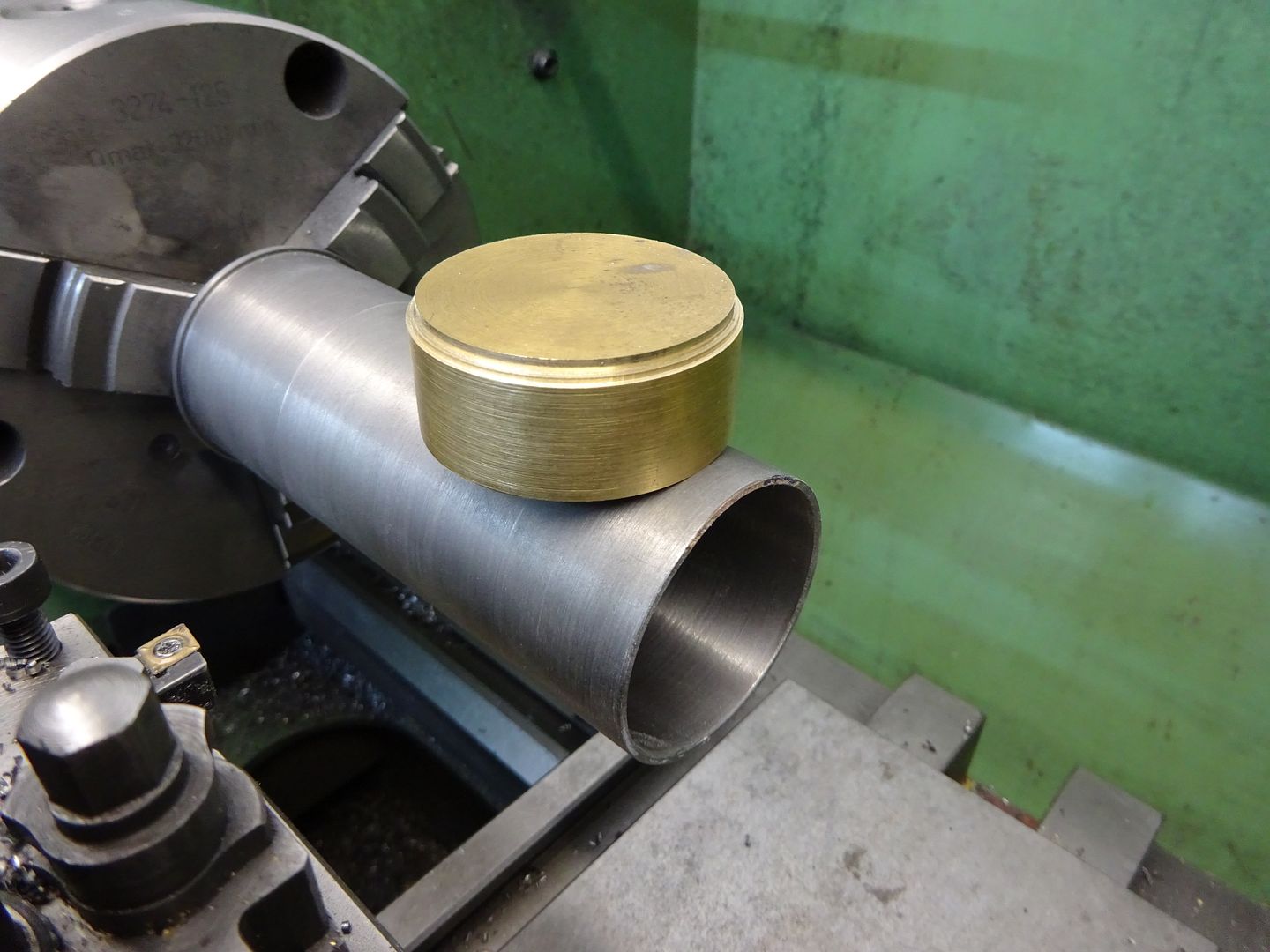
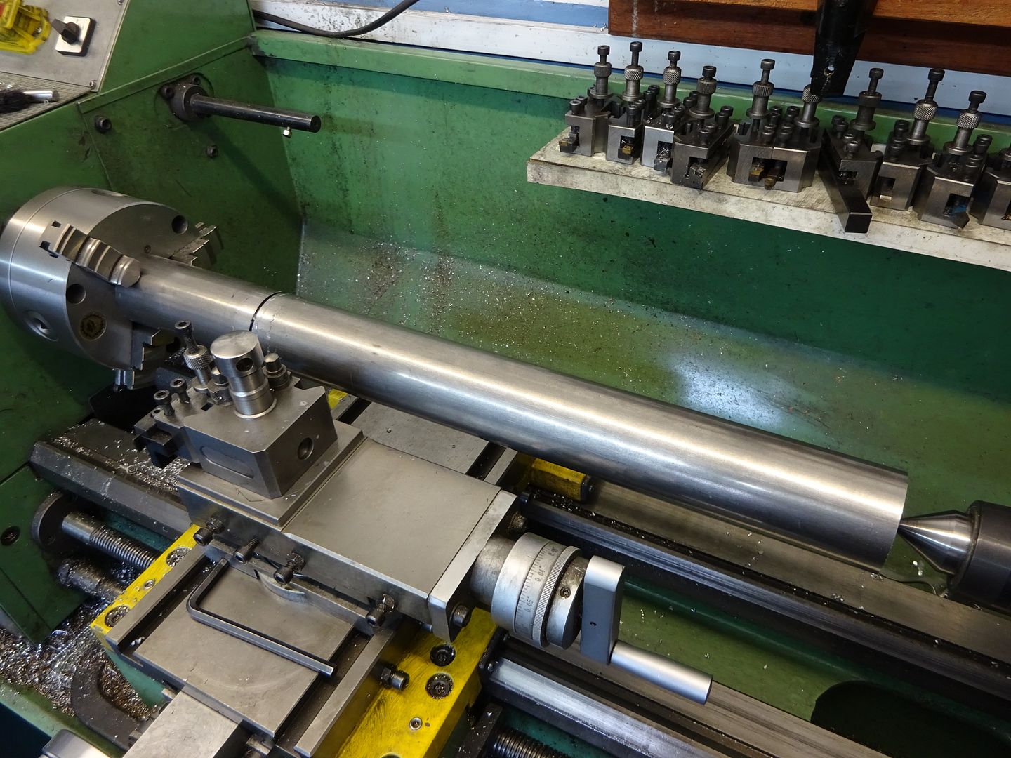
Groove/cutoff tools wants to dig in too much

Advert

Groove/cutoff tools wants to dig in too much

Home Forums Beginners questions Groove/cutoff tools wants to dig in too much

Viewing 24 posts - 26 through 49 (of 49 total)
  • Author
    Posts
  • #649335
    speelwerk
    Participant
      @speelwerk

      Being a Myford from (I guess) somewhere the 1950's, is there perhaps too much play in the headstock bearings because of wear. Niko.

      Advert
      #649339
      not done it yet
      Participant
        @notdoneityet

        Just a few more things to be aware of.

        Is the cutter positioned as close as possible over the centre line of the cross slide? That is the ideal position.

        How far from the chuck is this groove? The closer the better.

        Are you supporting the part from the tailstock? Every little helps, particularly if the groove is distant to the chuck.

        How far is the compound slide extended? The less the top slide is extended from its slide, the better (and tightened down – locked – securely).

        How much cutter overhang is there? The bare minimum is best. I adjust my parting tool extension for just over half way. If a large diameter, it gets adjusted more than once, starting short before extending.

        How good are the spindle bearings adjusted?

        if you have power feed on the cross slide, take extra care that the cut is stopped before the feed screw threads jam up!

        There may be more, but you get the idea that rigidity is paramount.

        #649342
        Fulmen
        Participant
          @fulmen

          Have you tried changing the tool height? There is no law demanding it be on center. Small tools flex, sometimes it helps to raise the tool slightly.

          #649349
          Chris Crew
          Participant
            @chriscrew66644

            My method of parting and grooving is with a good old fashioned J&S type holder with an Eclipse parting blade ground with about 5deg. front clearance and top rake (bottom rake as it's inverted) mounted up-side down in a rigid rear tool post very slightly above centre-height. Moderate speed, plenty of suds and a confident steady feed. Anyway, it works for me.

            All good quality lathes are made to face very slightly concave, so even if the tool is set at 90deg. to the work it will always be at a very slight angle to the work. This doesn't stop you from parting off or grooving successfully but just be aware of this design feature.

            #649357
            Kiwi Bloke
            Participant
              @kiwibloke62605

              Maurits, take heart, you're not alone. Parting, or even 'normal' turning with a tool with a large nose radius causes folk a lot of problems on small lathes. Essentially, it boils down to the desired relationship of the tool's tip and the work piece being disrupted, either by unwanted movement, or unintended forces.

              Myfords are relatively flexible, especially if using the topslide, and, as has been said, free movement of workpiece may be caused by worn mandrel bearings, or free movement of the tool may be the result of slop in the feedscrew nut or the feedscrew's thrust bearing, which is awkward to adjust nicely.

              In another thread, I asked why some early lathe-use books (and not so early: it's included in South Bend's 'How to Run a Lathe&#39 advocated setting the tool above centre height. As machines have improved, this advice has disappeared, but it shouldn't be forgotten. I'll now answer my question…
              A properly set up cutting tool experiences three forces: 1. force of feeding, towards tailstock; 2. away from the workpiece, pushing the tool out of cut; 3. tangentally downwards. This last force is by far the largest. It will try to bend the tool's support, and this will result in the tool cutting deeper – an unstable condition that will end in tears.

              It is important for there to be a force pushing the tool away from the work, because this takes up the feedscrew's two backlashes. The direction of force 3 (and therefore its horizontal radial component) is the major determinant of whether this occurs or not. If there is any inwards component of this force, the tool will get 'sucked in'. The idea of setting the tool on centre height (apart from avoiding facing pips) is to ensure this force is vertically downwards. If the tool is below centre height, the tangential force swings round, so there is an inwards component, trying to pull the tool inwards, deeper into cut. Of course, flexibility in the machine allows the tool tip to be deflected downwards, so it's all rather difficult to achieve theoretically correct conditions, all the time (ever?). Avoiding this is the justification of rear tool posts, with inverted tools: they deflect upweards and swing out of cut – a stable condition.

              The idea of setting the tool tip above centre height (tangent point about 5 degrees rotated clockwise, as viewed from tailstock), is to direct the tangential force 3 so that there is an assured outwards component, hopefully keeping the tool pushed outwards. Also, of course, it allows for downwards deflection of the tool.

              Beware of tools being below centre height. This is an unstable condition. At first sight, it looks attractive: a 'scraping cut' has to be safer than a 'proper' cut, doesn't it? Well, no! Emphatically no!

              #649377
              Kiwi Bloke
              Participant
                @kiwibloke62605

                Apologies for the yellow winking thingie in previous post. Too late to remove it now. Grrr!

                Just for clarification, before someone tells me that raising tools above centre height will prevent them cutting because they'll rub. What I've said assumes that tool angles are adjusted to account for the centre height variation. Think of it as rotating the tool and its point of contact clockwise about the lathe's axis, viewed from the tailstock. Tool movements remain conventional, of course.

                #649379
                not done it yet
                Participant
                  @notdoneityet

                  Do take Chris’ comment about ‘above centre’ with caution, unless/until he confirms the true precise position – in relation to it being upside down.🙂 Mine is just below centre, if anything, in this scenario.

                  I always expect some slight displacement from its rest position, while cutting. That force should be constant if power feeding (well, more consistent than my hand-feeding!).

                  Edited By not done it yet on 22/06/2023 05:25:38

                  #649382
                  Hopper
                  Participant
                    @hopper
                    Posted by Maurits van Dueren on 21/06/2023 21:03:20:

                    As to the metal, unknown but suspected a reasonably quality, but non-hardened one.

                    However, as mentioned, I have this all the time. It is worse now, as this is the largest diameter i've tried and a bit away from the chuck,

                    How far from the chuck? Anything more than maybe 25mm could start to be problematic. One solution is to put the fixed steady between the parting tool and the chuck to hold the job steady.

                    Is your tool holder holding the blade of your parting tool level? Or is it one that holds the blade at an angle?

                    #649384
                    Maurits van Dueren
                    Participant
                      @mauritsvandueren59568

                      @Kiwi Bloke

                      That part about the rear-end upside-down cut, bending the tool up and away (well, down and away) rather then into makes a lot of sense. It almost means we should do all cutting like that, if it were not for the problem of obscured visibility.

                      Talk about just above centre is also interesting. I was already trying that because I felt it would naturally give a negative top-clearance, making it want to dig in less. I had not considered the tool bending down also meant the tool post bending it in. (but that is now suddenly so very obvious)

                      It also means that any rear build post should ideally still be adjustable. At least at first, to experiment with this height. I think I'll make a simple block to mount the same QCTP. If nothing else, it would mean changing only one variable at the time gives better understanding.

                      #649386
                      Maurits van Dueren
                      Participant
                        @mauritsvandueren59568

                        @Hopper

                        Way too far. About 100mm but I have little choice in the matter, it is way to big to fit through the spindlebore. And I have no steady rest. But at least the workpiece is 46mm, so it least quite rigid itself.

                        I realize these things compound it all, but as stated, I have the same problem (but less extreme) with simple pot iron that I hold 5mm in front of the chuck, so I felt apart from these obvious faux-pas, there is also something deeper, like incorrect angles.

                        #649390
                        JasonB
                        Moderator
                          @jasonb

                          Can't you use backgear on the Myford which will give you a much lower speed while the motor is at 50hz and the increased mechanical advantage will reduce the tendency to stall. you should easily be able to get below 100rpm

                          #649392
                          David George 1
                          Participant
                            @davidgeorge1

                            This is my rear toolpost it is solid and after I had similar problems with my front mounted part off tool I havn't looked back and am only on my second tip in over two years of use.

                            20190316_144251.jpg

                            #649395
                            Hopper
                            Participant
                              @hopper
                              Posted by Maurits van Dueren on 22/06/2023 07:00:56:

                              @Hopper

                              Way too far. About 100mm but I have little choice in the matter, it is way to big to fit through the spindlebore. And I have no steady rest. But at least the workpiece is 46mm, so it least quite rigid itself.

                              I realize these things compound it all, but as stated, I have the same problem (but less extreme) with simple pot iron that I hold 5mm in front of the chuck, so I felt apart from these obvious faux-pas, there is also something deeper, like incorrect angles.


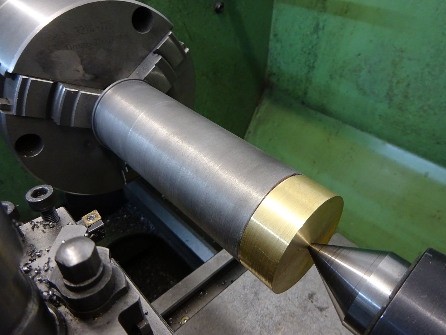
                              Yes way too far. You need to put the fixed steady, if you have one, between the chuck and the tool. Or you could centre drill the end and put a tailstock centre in place to stabilise it until you get down to the very last little bit before the end part comes off.

                              Another factor is quite possibly your old chuck is bell-mouthed, allowing the job to move around in the chuck and cause dig ins. This gets worse with large diameter work that can not fit back inside the chuck body. 45mm diameter in a small Myford chuck is not very stable at the best of times. Try mounting your job in the four jaw chuck and setting it to run true and see how that compares. The jour jaws grip better by nature and also that chuck usually less used and less worn.

                              But in the long term, rear toolpost definitely is the way to go on small lathes.

                              Edited By Hopper on 22/06/2023 07:50:28

                              #649397
                              Anonymous
                                Posted by Hopper on 22/06/2023 07:47:40:
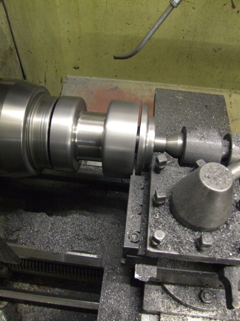
                                …centre drill the end and put a tailstock centre in place to stabilise it…

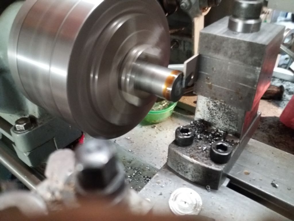
                                Like this, on a 3.5" diameter workpiece mounted on an homemade expanding mandrel:

                                Parting Front Wheel Hub

                                Andrew

                                #649400
                                Maurits van Dueren
                                Participant
                                  @mauritsvandueren59568

                                  Have no steadyrest. Have no 4-chuck. Can't centre drill, as the 46mm piece is also 25mm hollow. I did start yesterday making a sort of bull-nose adapter cone for my live centre, but did not try using it yet, as it got late.

                                  I guess I will use the bullnose anyway, even if only see the difference, but I think I need to go for the rear-post as default parting option anyway.

                                  Mind you, the steady/centre/bullnose and the rear post address different problems. One addresses stability of the part, the other of the tool, so they may at times both be needed.

                                  #649402
                                  JasonB
                                  Moderator
                                    @jasonb

                                    You can just make a stepped disc to fit into the hole and put a centre drilled hole into that

                                    Also if teh work can be turned around so the groove is at the chuck end that will help

                                    #649413
                                    John Haine
                                    Participant
                                      @johnhaine32865

                                      Another thing to be aware of is that you can try to part/groove at too low a speed. For the tool to cut there needs to be enough speed that in the small region where the tip touches the work the metal gets hot enough to soften. Manual feeding and going slow is particularly problematic since to start with the tool won't cut,you aren't feeding steadily because nervous about the whole process, so suddenly there's enough pressure for the tool to start cutting but then it pulls the slide forward so the tool digs in. I think it's George Thomas who recommends parting off at higher speeds using power feed – discovering that revolutionised parting off for me.

                                      #649417
                                      not done it yet
                                      Participant
                                        @notdoneityet

                                        Maurits,

                                        Don’t turn it around, in a 3 jaw chuck, if there remains any concentricity issues. Even removed and replaced the same way round is ill-advised, if concentricity is important.

                                        #649426
                                        noel shelley
                                        Participant
                                          @noelshelley55608

                                          The original Myford rear tool post was a solid lump of iron with a curved bottom to the groove for the tool holder and a curved part to fit, giving the ability to alter the tip height of the cutter. Depending on the tool angle effected the angles the tool had been ground to. A horizontal groove and shims might be just as easy ? The important thing is the rigidity of the set up ! Noel.

                                          #649435
                                          Neil Lickfold
                                          Participant
                                            @neillickfold44316

                                            Make sure that the backlash of the cross slide is set to the minimum. Any movement in the cross slide causes issues. The leadscrew and nut are normal replacement service items. Also make sure the gibs are not too loose on the topslide or on the cross slide. Once you have those done, your lathe will be fine.

                                            My S7 can is totally fine just grooving with the Dickson tool holders. I am after 36 years, thinking adding a rear tool post to save changing tools as much from just working on the front.

                                            At work they were having trouble with parting and grooving on a Cohlchester 1800 lathe, the leadscrew and nut for the cross slide, were worn out. With it replaced and the gibs all good, everything is fine with it.

                                            With parting and grooving tools, they are normally right on centre height, or just very slightly above, maybe 2 thou or so, 0.05mm for metric.

                                            Worn 3 jaw chuck or worn can also cause issues when grooving. You can change to a 4 jaw, or sometimes hold the part with card thin card can help with the vibrations from a chuck that is stressed and is holding tighter on the back than evenly along the jaw length. Worn 4 jaw chucks can have the same problem as worn 3 jaw chucks too.

                                            #649501
                                            Fulmen
                                            Participant
                                              @fulmen

                                              100mm stick-out with no end support is asking for trouble. Start with a bull-nose adapter and tighten the gibs. Raising the tool slightly to compensate for deflection can also help.

                                              #649692
                                              old mart
                                              Participant
                                                @oldmart

                                                Maximum rigidity helps a lot, plus I always lock the saddle. Rear inverted parting blades fixed directly to the cross slide are best and gravity helps with swarf removal. If using blades with carbide tips, you may be able to get different grades of insert, and they like to cut and not rub. I have had better results with a bold approach, the main difficulty is keeping some lubrication in the cut while still advancing the tip.

                                                #649693
                                                Maurits van Dueren
                                                Participant
                                                  @mauritsvandueren59568

                                                  Ok, I am making some progress:

                                                  – Made a bull nose adapter (basically a big 45 degree cone that fits round the 60 degree life center. This already makes a huge difference.

                                                  – Used the back gear. I had completely forgotten i had such, someone here mentioned it. It is the first time I use it. Now working in the 60~120 RPM range with plenty of torque.

                                                  – Put the cutter a bit more above centreline, as suggested.

                                                  Result: Much better. Some new problems, but much better,
                                                  Did not build a rear post yet, as I felt I wanted to see how this worked, and much better.

                                                  Now, what I am seeing, especially in the 60RPM range that my eyes can follow, is HOW MUCH everything bends. It's like the whole thing is made of plastic. My god, all the iron needs to be twice as thick! Not sure I can do anything about the cross-slide itself bending over backward, but that tiny 0XA toolpost that I selected because no other quick change post would fit between topslide and centreline, well, it is too tiny.

                                                  What stops me now however, is the fact the toolpost is only secured by a centre-bolt. The cutting tool is of course left of the bolt, so a rotation force is created, and I cannot tighten it enough to keep it from rotating, thus rotating the groove tool to the side.

                                                  I had seen it before, where a PIN prevent such rotation, but my topslide, nor my QCTP have those.


                                                  Edited By Maurits van Dueren on 23/06/2023 17:14:32

                                                  #649754
                                                  Howard Lewis
                                                  Participant
                                                    @howardlewis46836

                                                    On my lathe (Bigger than a ML7 ) the front toolpost locates against, for want of a better word, a taper topped dowel.

                                                    My home made indexing four way rear toolpost locates against the rear of the cross slide with two 1/4" dowels. The toolpost is prevented from rotating on it's base, in each position by nothing bigger than a 1/8" dowel.

                                                    The parting tool, mounted inverted in the rear toolpost is 3/32" wide, and deep, on centre height, with no top rake.

                                                    Using power cross feed for parting off (Have become braver in old age ) is at a feed of 0.00225/rev

                                                    For parting off larger sized material, 12mm or larger, drip feed (Syphon fed from a bottle above the lathe ) of soluble oil is uded. Rotation speed is fairly low, minimum provided by bnthe VFD in middle belt position, so circa 90 rpm.

                                                    So, my advice?

                                                    Sharp tool, no top rake, mounted at centre height in a rear toolpost, wyth minimal overhang to maximise rigidity, , (Yes you can see things flexing, but my very old tool holder is intended to flex! ) Mounting above centreline menans that things flex to bring bthe toll to cednytre heihjt, or even slightly below.

                                                    Low speed, slow feed, (DON'T force it! ) and soluble oil feed. Some times, ordinary lubricating oil, applied with a brush.

                                                    Dig ins DO happen, but very rarely compared to the number of times that work is parted off, without breaking the tool.. And a slow resumption of feed gradually removes the "lump" and things then proceed as normal.

                                                    For my mini lathe, I made a rear toolpost located against the rear of the Cross Slidem by a rebate (Base is milled to leave a 3mm deepx 3mm thick rebate across the rear ). It carries a 1.5mm parting tool. Having no T slots, the post is secured to the Cross Slide (Unfortunately ) by an off centre M6 stud and nut, but seems to work on the rare occasions that the machine is used. Being small cutting is usually dry.

                                                    Being a mini lathe, infeed has to be manual.

                                                    Because the stud is off centre, the nut needs to be really tight.

                                                    HTH

                                                    Howard

                                                  Viewing 24 posts - 26 through 49 (of 49 total)
                                                  • Please log in to reply to this topic. Registering is free and easy using the links on the menu at the top of this page.

                                                  Advert

                                                  Latest Replies

                                                  Home Forums Beginners questions Topics

                                                  Viewing 25 topics - 1 through 25 (of 25 total)
                                                  Viewing 25 topics - 1 through 25 (of 25 total)

                                                  View full reply list.

                                                  Advert

                                                  Newsletter Sign-up