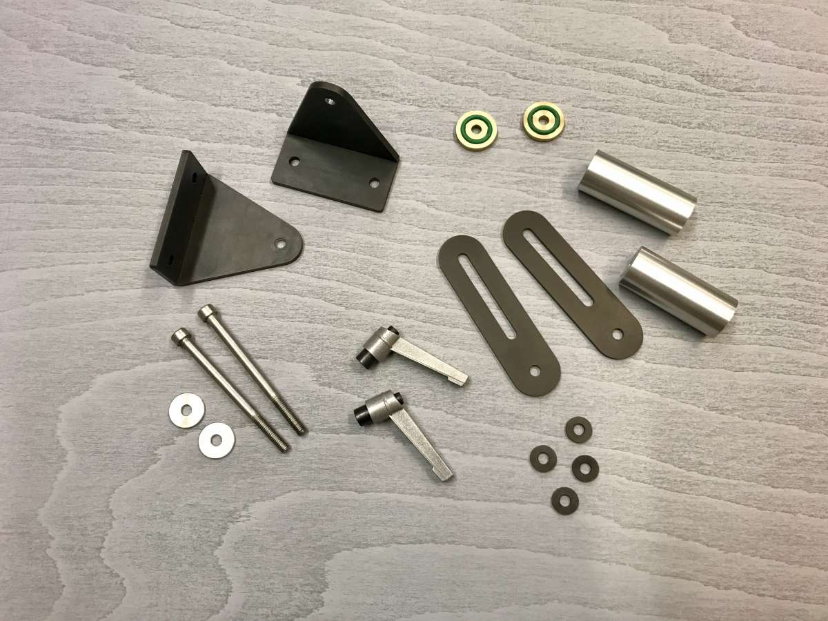
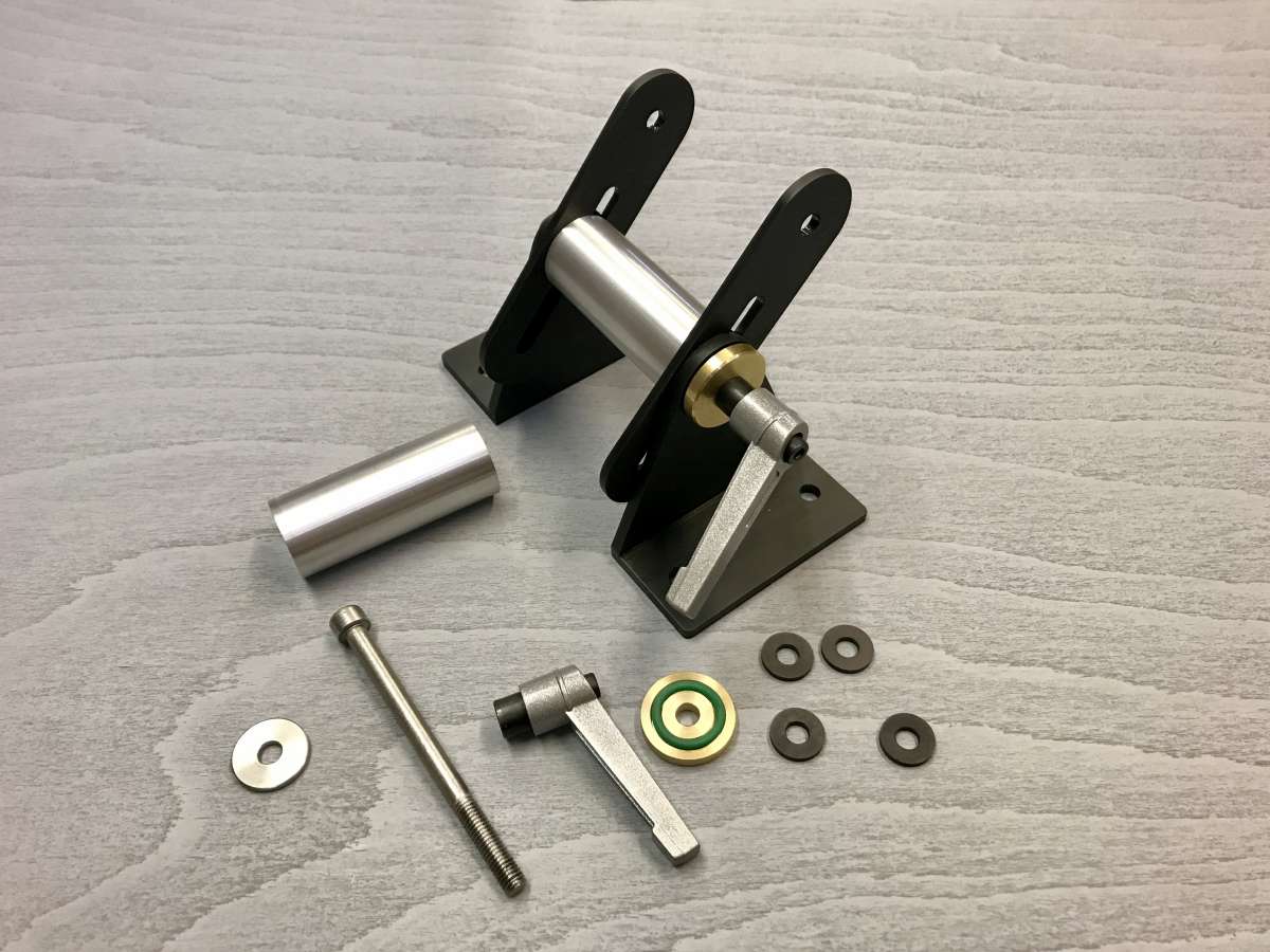
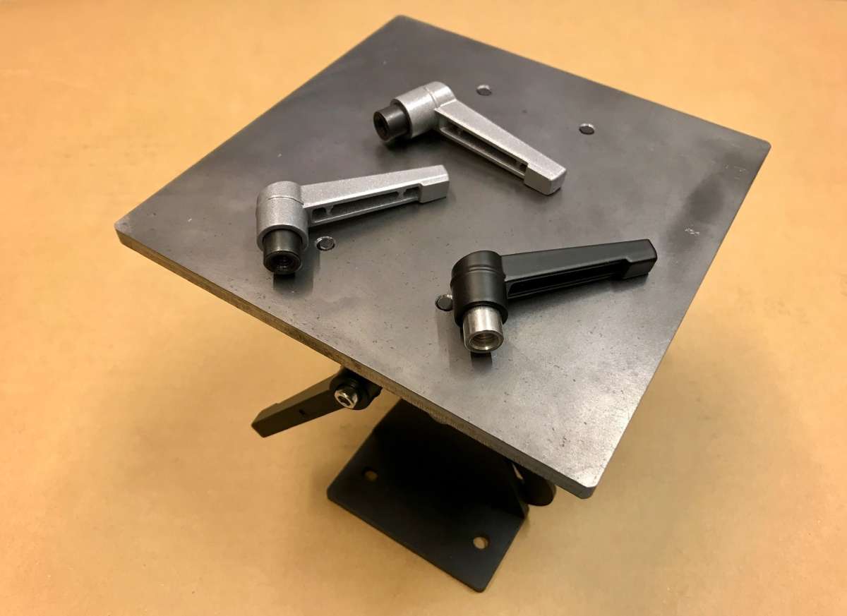
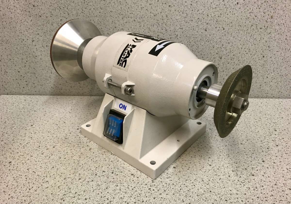
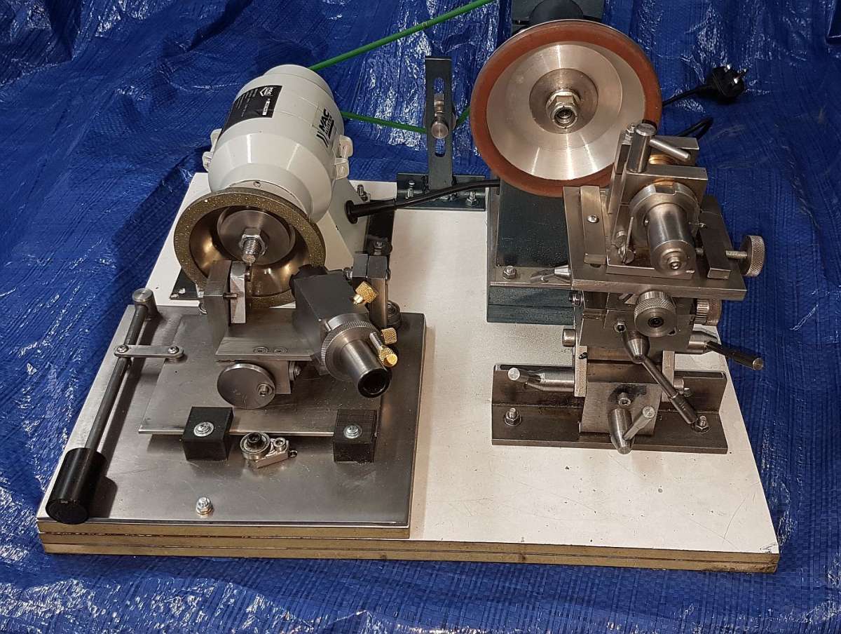
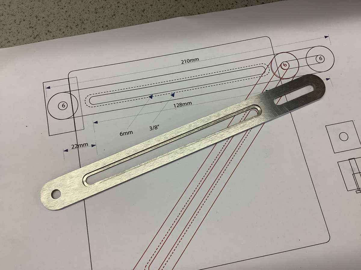
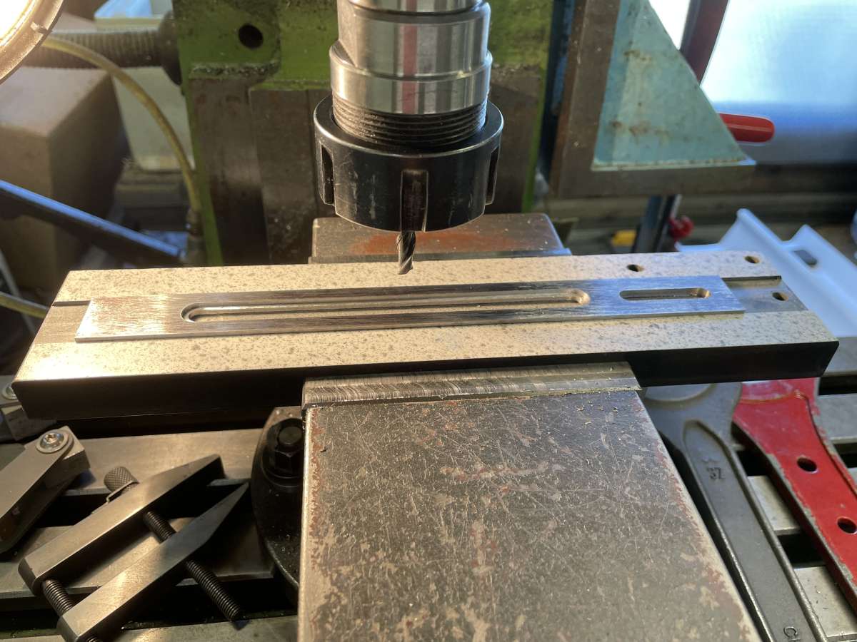
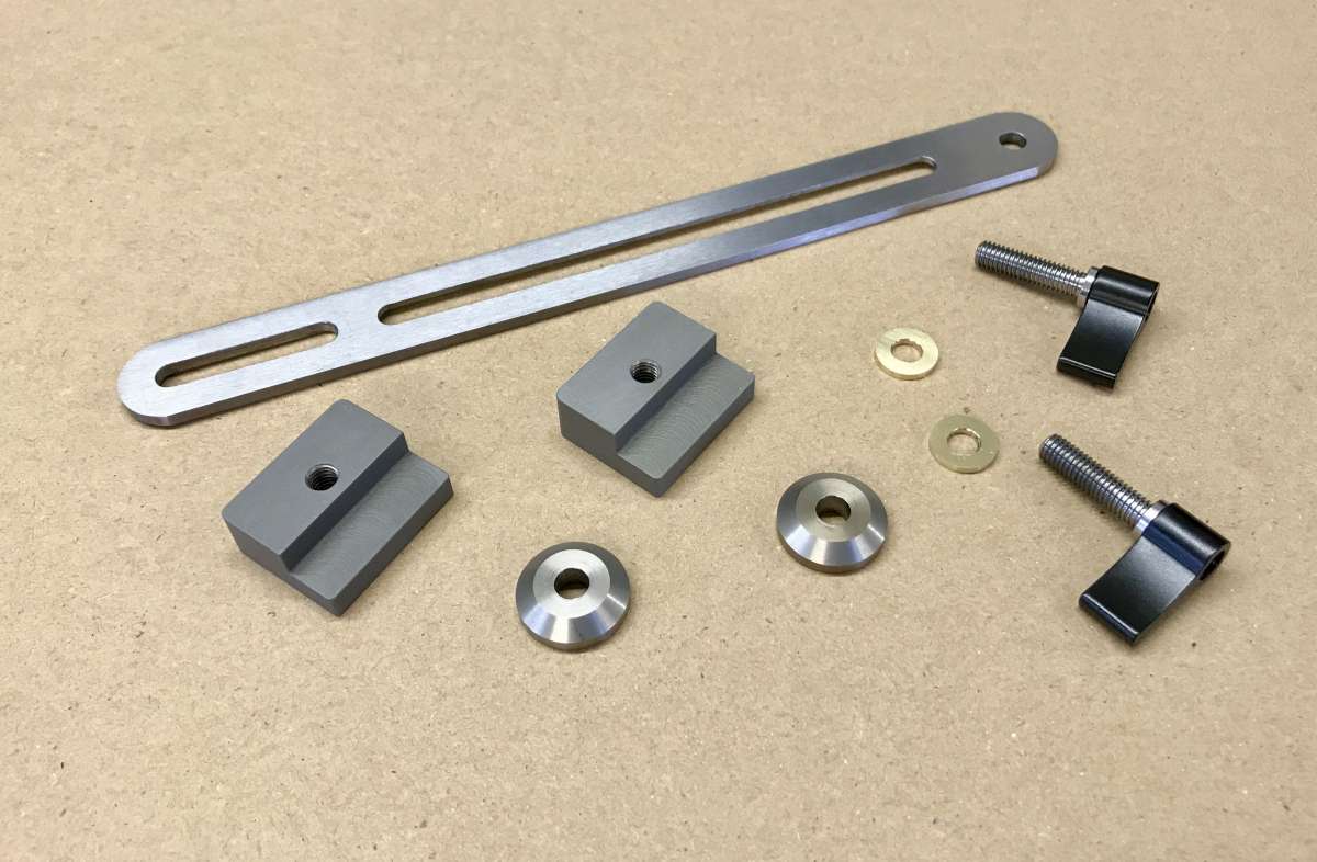
Grinding Rest

Advert

Grinding Rest

Home Forums Workshop Tools and Tooling Grinding Rest

Viewing 25 posts - 1 through 25 (of 41 total)
  • Author
    Posts
  • #737386
    Vic
    Participant
      @vic

      My current project was progressing quite nicely but unfortunately an eBay supplier hasn’t shipped the material I need for the top brackets. Once I get a refund I’ll try another supplier.

      IMG_9226IMG_9228

      Advert
      #737414
      Mark Rand
      Participant
        @markrand96270

        Painted or blued? If so which process?

        As the years go on, the offcuts collection builds to the point where one can make a modest ocean liner out of the bits lying about the shed. 🙂

        #737417
        Nick Wheeler
        Participant
          @nickwheeler
          On Mark Rand Said:

          Painted or blued? If so which process?

          As the years go on, the offcuts collection builds to the point where one can make a modest ocean liner out of the bits lying about the shed. 🙂

          More like a weird looking dinghy once you’ve discounted the scraps that are slightly too small for the part, or far too good for this project.

          #737429
          Vic
          Participant
            @vic
            On Mark Rand Said:

            Painted or blued? If so which process?

            As the years go on, the offcuts collection builds to the point where one can make a modest ocean liner out of the bits lying about the shed. 🙂

            Sand blasted first, then dipped in gun blue and oiled.

            #737531
            ega
            Participant
              @ega

              They look very nice.

              Should there be an acknowledgment of the source of the design?

              #737537
              Vic
              Participant
                @vic

                Yes, it’s based on the Acute rest. All of the components so far are different in *size though.

                *Why? Because I’ve been working either with materials to hand or easy to source. I decided to make the bottom brackets wider and with a thicker section because it was convenient, and may perhaps make the finished rest a little more stable? The side straps were made bigger because it required less stock removal. Some of the other components will also be bigger to accommodate a tool holder I’ve already made.

                Some materials can be quite good with square edges and a reasonable surface finish, and can pretty much be used as bought, apart from some shaping and drilling. Other supplies were bought over size and milled/turned down.

                #739518
                Vic
                Participant
                  @vic

                  Some context. I decided quite a number of years ago that I could do with a decent grinding rest. Some of those I looked at were rather small so I looked at ones like the Harold Hall rests. The advanced model looked to be more of an investment in time and materials than I wanted to spend. More recently I looked at the HH rests again together with the Acute and a few others online and on YouTube. I decided that the basic table of the Acute might be a good starting point and it had a nice size – 150mm x 150mm table.

                  I looked at some YouTube videos of the table together with some online build logs. I decided that an exact copy was not required but the basic substrate looked quite good. I was on a tight budget so working with raw materials seemed the logical option. I was going to just buy the plans but discovered the majority of the information required to start a build was freely available from build logs etc and the other dimensions were easy enough to work out.

                  I decide to use steel angle for some of the parts but this proved to be quite time consuming and the finish after machining to true it up left something to be desired. Aesthetics aside though the parts are ok mechanically. I chose to make them somewhat bigger than those in the plans with a 25% increase in thickness and a 10mm increase in the length for the feet. I also decided to increase the thickness of the table to 6mm. This gives a deeper thread for the mounting screws. If I were to do this again I might just buy some angle brackets as I’ve seen some on eBay that could, with some adjustments to the plan, be suitable. Failing that, solid stock would suffice.

                  I decided that having the plans may be useful for future reference but having bought a set I had to cancel the order as the vendor was away and unable to supply them for several weeks. If anyone else is planning a similar build then the plans look good and aren’t expensive but not absolutely necessary unless perhaps you want to build an exact copy. I’ve already made a tool holder that I’d like to use if I can so I’ll have to do some redesign anyway to use it.

                  looking online some of the reviews about the test aren’t too positive but there are always variables with a self build that can obviously affect accuracy and useability. There are also some small criticisms of the kit components and substitute materials have been used to make machining easier. I’m not overly impressed with the decision to use cap bolts as pivots as locking the assembly could be an issue. The instructions (ignored by some YouTuber’s) to drill two holes slightly under size is not a particularly good solution in my view. If, in spite of my following the instructions, the unit doesn’t lock easily and positively I may use 6mm threaded rod and a knob as well as a locking lever.

                  I need to source some more materials and produce some simple drawings before I can continue the build. It can though already be used as a simple adjustable rest which I didn’t have before.


                  #739568
                  derek hall 1
                  Participant
                    @derekhall1

                    I built the Harold Hall simple grinding rest design, and although it sort of worked, there was a lot of faffing about to set up angles with templates, magnetic clamps etc. I did not bother with the slot/endmill attachment, as I was dissappointed with the results I was getting from the attachment.

                    It was a bit of a waste of my time to build it to be honest.

                    Cannot comment on the advanced version, but seen some criticism of both designs (simple and advanced). The advanced version looks to be a lot of work that still has limitations.

                    A lot depends on what you want to grind/sharpen and how accurate it needs to be…

                    #739576
                    Vic
                    Participant
                      @vic

                      The HH simple rest looked a bit flimsy. The advanced looked over complicated. Both of them have rather small tables. As you say, much depends on what you want to sharpen. Ease of use will no doubt play a part in determining that for me.

                      One of the features I noticed about the HH rests is the guide slots in the table. A nice idea but perhaps not as flexible as the guide fence on the Acute rest.

                      I quite liked the rest in this video but some of the elements were even more complex than the HH advanced. Check out the other videos in the series if it’s of interest.

                      #739672
                      Vic
                      Participant
                        @vic

                        A couple more bits arrived today.  The table needs some small locking levers. I ordered a two pack of the silver ones on Amazon but also placed an order for three of the black ones from Aliexpress. These have stainless M6 fittings. They are all female and I need one male so I’ll Loctite a socket set screw into one of them.

                        IMG_9234

                        This is the grinder I’m hoping to use. They cost between £22 and £25 in most places. The type has featured in a number of online builds so I expect it should be fine. It’s currently fitted with a 100mm resin Diamond cup wheel on one end and a 75mm electroplated Diamond disc on the other.  I’m hoping to get a CBN wheel at some point.

                        IMG_9235

                        #739952
                        martin haysom
                        Participant
                          @martinhaysom48469

                          i used one of those grinders on my H H tool rest build. check the cycle time is suited for your use they get hot very quick. an old one that came from the same shop 40 years will run for hours and only ever gets slightly warm [ i got distracted and left it running]

                          #739962
                          Vic
                          Participant
                            @vic

                            These grinders are tiny. About half the weight of a similar looking one I’ve had for over 30 years. The new one is only going to be used for light work and it’s diminutive size and weight will be a definite advantage.

                            When I need to remove large amounts of material I use 60g on my belt grinder.

                            Edit: Not my setup, just something I saw online using the same grinder. I’ve seen several others.

                            IMG_0403

                            #741221
                            Vic
                            Participant
                              @vic

                              I was very lucky today. I drew up the fence with the changes I wanted and had time to make a start today. The only suitable sacrificial material I had to hand was a small piece of compressed paper/resin bench top. I was going to clamp both parts to the mill table but decided instead to clamp it in the vice. It then occurred that rather than clocking the part I could just cut a shallow rebate for it instead.

                              To reduce the amount of machining I chose to use some 20mm x 3mm ground flat stock. As I got close to the size of rebate required for it, it was clear something wasn’t quite right. Measuring the GFS showed that it was over size at 20.15mm. I wouldn’t have noticed this if I’d just clocked it and the resultant slots in it would have been off.

                              This was the setup after removing the clamps, and the finished part.

                              IMG_1242IMG_3017


                              #741603
                              Vic
                              Participant
                                @vic

                                Next job is a couple of clamping elements for the fence. The plans call for two completely different clamping elements. One of them is round and the other might best be described as an orange segment shape?! 😆  I’ve no idea why this is the case. I suppose if you’re supplying a laser cut kit of parts you can have any shape you like? Not so practical though if you’re working from plans. There may actually be a good reason but I’ve decided to take the risk and make something a little easier. First impressions are though that they seem to clamp very well. Once again size was fairly arbitrary, dependent on available stock. I’ve also elected to use different size fasteners than those listed. I got into the habit years ago of trying to limit the number of different threads on projects if possible. It had practical reasons at the time. This project calls for M3, M4, M5 and M6 threads. I’m expecting to use just M4 and M6 as I don’t see any advantage in using the others. I’m particularly impressed with the little M6 “Flag” style aluminium locking levers I ordered from Aliexpress. I’ll also be using an M4 version for the fence block.

                                IMG_9303

                                IMG_9304

                                #741604
                                Vic
                                Participant
                                  @vic

                                  Once again I’ve changed the size (and material) of the next component on my list, the T nut for the fence. This part should have a 5mm spigot with a 4mm thread in it. I decided the wall thickness was a bit on the thin side so I cut a 6mm slot in the fence so I could increase the spigot accordingly. Material will probably be Brass so it slides nicely in the fence rebate. I’m undecided on the stop block that sits above the T nut. Size can be anything I like (as usual on this project 😆 ) but I’m unsure of whether to make it in mild steel or aluminium alloy?

                                  #742377
                                  Vic
                                  Participant
                                    @vic

                                    I mentioned earlier that I wasn’t happy with the concept of using a long cap head socket screw for the pivots. I came across some nice looking M6 plastic wing nuts with brass inserts so I bought a couple. They seem to work well but I’ll have to see how it goes when I’m actually using the rest. They are small enough that they don’t foul any other components.

                                    IMG_1361

                                    #743652
                                    Vic
                                    Participant
                                      @vic

                                      The next part I’m making is the stop block. It looks like this. I’ve been contemplating alloy or mild steel for this part. Both would be ok but I need some stainless steel rod for a job so I could nick a bit off the end for this part. I hate stuff going rusty. I’ve not machined 303 stainless before. I’m hoping it mills pretty well?

                                      IMG_1418

                                      #743683
                                      ega
                                      Participant
                                        @ega

                                        Vic

                                        Don’t the plastic wing nuts negate the adjustability of the Bristol handles? My standard build works fine. I agree the under size hole sounds a bit agricultural, though.

                                        #743728
                                        Vic
                                        Participant
                                          @vic

                                          I’m not sure what you mean but once the locking lever is tight you can adjust it to any position required. As mentioned, if it does become an issue I can go back to the bolts and maybe use stud lock or something?
                                          I have seen other solutions that I’m not so keen on:

                                          IMG_0824

                                          #743927
                                          Vic
                                          Participant
                                            @vic

                                            On the latest Blondihacks build she says the bolts do tend to loosen and she’ll probably replace them with hex bolts and *weld a stop. In fairness I’m not sure if she took notice of the instructions saying to drill the brackets slightly undersize for the bolts? I did, but then decided to use slightly longer bolts, and you guessed it, they were fractionally smaller.

                                            * I don’t have a welder so I’d have to do something else if my little wing knobs don’t work.

                                            IMG_1496

                                            Video:

                                            https://youtu.be/YiQoHcsvV2A?si=ydIrsYHhMJ-j2Fti

                                            #744000
                                            ega
                                            Participant
                                              @ega

                                              I suspect that if mine began to slip I would resort to keeping a hex key handy.

                                              #744144
                                              Howard Lewis
                                              Participant
                                                @howardlewis46836

                                                Glad that you are increasing sizes if the material is available. That can only improve rigidity, which is what you want to grind accurately.

                                                Looks good!

                                                But can’t see the point of having Bristol levers in conjunction with a wing nut.

                                                The picture with ball ended levers shows why Bristol levers are so useful, to avoid fouls.

                                                A M6 thread can apply a large clamping force, so unlikely that anything would move much under the loads imposed by grinding.

                                                Howard

                                                #744532
                                                Vic
                                                Participant
                                                  @vic
                                                  On Howard Lewis Said:


                                                  A M6 thread can apply a large clamping force, so unlikely that anything would move much under the loads imposed by grinding.

                                                  Howard

                                                  The problem seems to be that the bolt is not captive. I’m a way away from using mine yet but Quinn in her video mentioned it loosened in use.

                                                  Too hot in the shop but I did a little job, a knob for an adjuster. Once again I chose to use a larger size. M4 instead of M3. M3 is handy in that one revolution = .5mm but the knob isn’t graduated so I went with M4.

                                                  Now, should I sand blast it the same as the other, smaller knob in the picture?

                                                  IMG_1575

                                                  #746913
                                                  Vic
                                                  Participant
                                                    @vic

                                                    I confess the project has stalled temporarily. I’ve had other more pressing jobs to do in the workshop plus house maintenance – jet washing the facia, soffits and gutters etc. I wasn’t sure how far I was going to take this build anyway but until I have time to restart, at least I have a decent grinding rest which I didn’t have before. I just need to fabricate some guards for the wheels. On one of the websites I’ve been getting a lot of my ideas from I noticed that the majority of builders haven’t bothered fitting guards but I’d like to contain the dust for more efficient extraction if I can. The table adjustment didn’t work as well as I hoped when I set up for this shot. The bolts or threaded rod, really needs to be firmly attached on one side of the table. I’m not sure how to achieve this yet but I’ll work something out. Its solid enough as it is but I can get it better.

                                                    IMG_1785

                                                    #746916
                                                    Vic
                                                    Participant
                                                      @vic

                                                      Of the few builders that did fit a guard on the website I mentioned, I found this solution quite inventive! I must remember to take a tape measure with me the next time I go to Sainsbury’s! 😂

                                                      If you’re of a sensitive disposition please don’t view the following picture! I don’t want anyone going apoplectic again. 😆 Yes I know there are exposed terminals and the motor has openings. It’s not my grinder and I’m not suggesting anyone else do this. I’m hoping the owner resolved these issues before using it. 😉

                                                      IMG_0489

                                                    Viewing 25 posts - 1 through 25 (of 41 total)
                                                    • Please log in to reply to this topic. Registering is free and easy using the links on the menu at the top of this page.

                                                    Advert

                                                    Latest Replies

                                                    Viewing 25 topics - 1 through 25 (of 25 total)
                                                    Viewing 25 topics - 1 through 25 (of 25 total)

                                                    View full reply list.

                                                    Advert