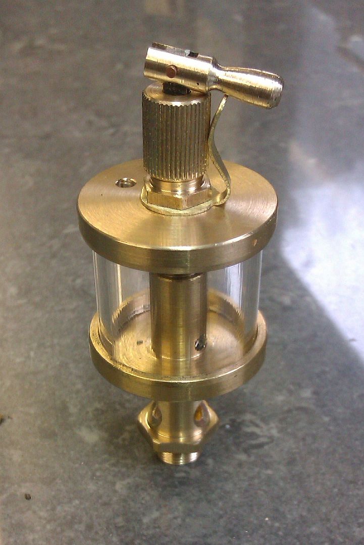
Glass Drip-oiler Design / Manufacture Advice
Glass Drip-oiler Design / Manufacture Advice
- This topic has 17 replies, 9 voices, and was last updated 24 August 2022 at 12:45 by
 Andy_G.


- Please log in to reply to this topic. Registering is free and easy using the links on the menu at the top of this page.
Latest Replies
-
- Topic
- Voices
- Last Post
-
-
Dodgy car parts a new low
Started by:
jon hill 3
in: The Tea Room
- 2
-
26 April 2025 at 00:45
howardb
-
Scam email
Started by:
Ian McVickers
in: General Questions
- 6
-
26 April 2025 at 00:43
halfnut
-
Poor Experience with Auction Site Seller
Started by:
Chris Crew
in: The Tea Room
- 10
-
25 April 2025 at 23:58
Paul Mills 4
-
VFD on single phase to control speed?
Started by:
beeza650
in: Beginners questions
- 5
-
25 April 2025 at 21:54
Ian P
-
leftover gear oil uses?
Started by:
jon hill 3
in: Beginners questions
- 2
-
25 April 2025 at 21:51
Howard Lewis
-
Tensile Strength Machineability
Started by:
kevian64
in: Beginners questions
- 12
-
25 April 2025 at 21:43
Howard Lewis
-
battery charger
Started by:
duncan webster 1
in: Electronics in the Workshop
- 14
-
25 April 2025 at 21:18
Trevor Howley
-
Drummond round bed
Started by:
old mart
in: Manual machine tools
- 2
-
25 April 2025 at 21:16
Bazyle
-
Lady Stephanie
Started by:
Steve Huckins
in: General Questions
- 5
-
25 April 2025 at 20:28
alan ord 2
-
Bending EN24t
Started by:
vintagengineer
in: Workshop Techniques
- 1
-
25 April 2025 at 20:27
vintagengineer
-
Arduino controlled stepper motor for Mill X-axis drive
1
2
Started by:
nevillet
in: CNC machines, Home builds, Conversions, ELS, automation, software, etc tools
- 12
-
25 April 2025 at 20:22
SillyOldDuffer
-
Coolant Hose Kit
Started by:
Me.
in: General Questions
- 5
-
25 April 2025 at 20:04
DC31k
-
1920s Cradle Mic Antique Brass Sleeve
Started by:
paulc1
in: Help and Assistance! (Offered or Wanted)
- 6
-
25 April 2025 at 19:42
bernard towers
-
3D printer choices
1
2
Started by:
Matt Harrington
in: 3D Printers and 3D Printing
- 13
-
25 April 2025 at 18:51
Michael Gilligan
-
Power hacksaw – powerful banging when running
Started by:
ell81
in: Beginners questions
- 6
-
25 April 2025 at 18:07
Diogenes
-
Gas Engine Needle Valve
Started by:
Chris V
in: General Questions
- 7
-
25 April 2025 at 16:46
Howard Lewis
-
Hello from Sunny Skegness
Started by:
kevian64
in: Introduce Yourself – New members start here!
- 8
-
25 April 2025 at 16:28
Howard Lewis
-
1920s Cradle Mic Antique Brass Sleeve
Started by:
paulc1
in: Help and Assistance! (Offered or Wanted)
- 2
-
25 April 2025 at 15:01
JasonB
-
Fitting DRO to Myford VME mill.
Started by:
Martyn Cozens
in: Manual machine tools
- 4
-
25 April 2025 at 14:56
SteveP
-
Low Current Power Bank
Started by:
Alan Wood 4
in: Electronics in the Workshop
- 6
-
25 April 2025 at 11:32
Michael Gilligan
-
Mechanical lubricator
Started by:
Garry Coles
in: General Questions
- 1
-
25 April 2025 at 09:56
Garry Coles
-
Broken casting – Best repair?
Started by:
John McCulla
in: Workshop Techniques
- 8
-
25 April 2025 at 09:43
Clive Foster
-
How To Make A Pressure Gauge Syphon?
Started by:
MEinThailand
in: CAD – Technical drawing & design
- 4
-
25 April 2025 at 09:37
JasonB
-
original benz
Started by:
tom hardy
in: General Questions
- 4
-
25 April 2025 at 09:21
JasonB
-
Building Bernard Tekippe’s Precision Regulator
1
2
Started by:
Chris Raynerd 2
in: Clocks and Scientific Instruments
- 11
-
25 April 2025 at 06:25
Michael Gilligan
-
Dodgy car parts a new low


