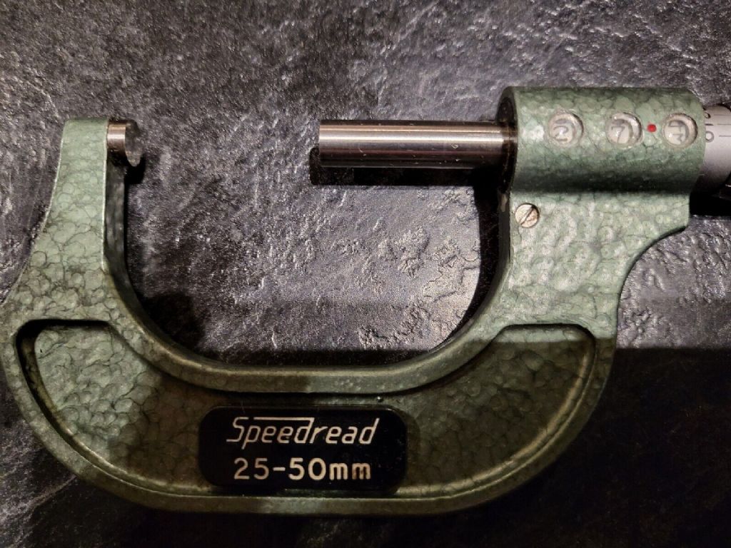
For completeness in case anyone searches for this in the future.
A Few Notes on Re-indexing a GKN-Shardlow 25-50mm Speedread Micrometer.
N.B. is isn’t an official procedure, and very much trial an error, with lots of the latter.
Please read in conjunction with the US patent for a micrometer from 1956 by Davenport.
**LINK**
A recent purchase of a good used example of this micrometer arrived with the direct reading numeric display out of sync with both the spindle and adjacent digits.
I believe Screw No.60 on the original patent diagram vibrated loose whilst the parcel was in the post
This led to an eccentric spindle, Part No.52 moving and allowing the small gear No.46 to disengage.
Unfortunately, unlike the original from 1916, this spindle is made of plastic, and also seems to have an eccentric pivot allowing an adjustment of the gears’ engagement.
Screw No 60 is the one just below and to the left of the first digit display window.
Disassembly (partial)
First I needed to partially disassemble the instrument, but fortunately I didn’t need to dismantle the gearbox or display itself.
The thimble is held on a taper at the end of the main spindle No.14 but just removing the end screw only releases the knurled adjusting collar.
N.B don’t lose the ratchet spring, and note it’s orientation before removing.
I’ve no idea how you are supposed to release the thimble from the taper without a special tool, but this worked for me; unscrew the thimble as far as it will go and wind it back in very slightly to avoid straining anything.
This exposed the collar used to compensate for thread wear, nut note that’s it’s the plain black ring with the C spanner hole, rather than the nut No.10 on which it’s mounted. I used the end of a 12” steel ruler in the gap as a lever, and the thimble pinged off without too much effort, though a mini hot air gun might help if it’s tight.
Wind the main spindle half in towards the 25mm end, and remove the nut No10, complete with the thread wear compensation ring; I loosened the ring as well so I had a better feel for what was happening. You might need to adjust the spindle in one direction or the other as the nut comes out of the main bore.
The main spindle No.14 will slide out complete with nut No10 Put the nut to one side, but note that the outer thread on it appears to be coarser than the one on the main spindle.
I think that the spindle thread might be multi-start, as when you screw the nut back in later, the spindle moves outwards.
Note the collar No34 on the spindle No.44 with the lug No. 30 and look down the bore for the groove in tube which it engages to turn the gearbox/display.
I now re-inserted the spindle, which is a sliding fit and used that to turn the inner tube/sleeve to line up the numbers on the display wheels. Gently tightening screw No60, in conjunction with rotating the plastic grub screw, locked the eccentric spindle No 52, and allowed a smooth drive to the display wheels. (The plastic screw is effectively No 54 on the patent, but slightly different in this production version)
Re-assembly to follow in the next post
Bill
 peak4.


