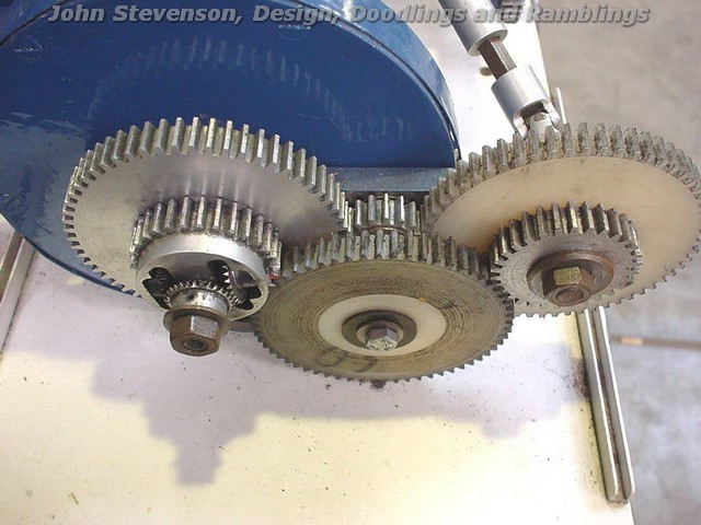
Hi Gustav, I've found some emails from 2003 to a chap called Michael Durkin where we tried to work out the hobber workings and some of the numbers around it. He kindly dug out some of the following pictures for me which he took at the Harrogate show. He also gave me the following explanation of how the differential worked. I'll have a deeper look for the spreadsheet as well, but with the picture and the description it should hopefully be enough to make your own differential. I'll try and dig out the calculations as well as that will get you to a point where you can cut the primes from non-prime gear sets.
"…I have figured out the differential. I noticed that the gear being cut has 36 teeth, so I tried a teeth counting exercise on the photos and tried to add everything up to arrive at 36 teeth on the blank.
I did so in this manner (you need to look at the photos at the same time!):-
Input from the motor drives the big gear behind the one with the differential, (I think they are on co-axial spindles, but not coupled), this has 60 teeth.
I think this gear is coupled to one of the differential wheels, the rear one, facing the one visible on the hob drive shaft. It also drives an idler (don't care about teeth on this) which you can just see 4 teeth of, and then onto a 60 tooth Acetal gear. This latter drives the worm and wheel, which seems to be a 36 tooth job.
The 60 tooth Acetal gear is coupled to a 30 tooth Aluminium gear and via another (Acetal 60 tooth) idler, drives the 30 tooth gear which also forms the differential cage.
I did the "mind game" involved with this differential and if the rear gear is driven at, for example, 100 rpm c.w., then this would drive the visible differential gear at 100 rpm a.c.w. if the cage was static. With the fitted gears, the cage is also driven at 100 rpm c.w., which would drive the visible gear at 200 rpm c.w. if the rear gear were static. The differential acts as a summer and the final speed of the visible gear (and the hob) is the sum of the two resultant input motions, 100 rpm c.w.
Of course, by playing with the ratios of the train between the big gear and the differential cage, you can play with the speed of the hob and the speed of the worm.
The worm acts as a 36 to 1 reducer and would have an input of 100 rpm, so the blank would rotate at 100/36 rpm. This is exactly right for the gear we look to be cutting.
I set this up in an Excel spreadsheet and played with the available change gears in a Myford set (maybe 2 sets for some ratios). It will generate lots of different outputs. If you change the worm gear, this adds even more.
I intend to analyse it further, because I think some interesting possibilities arise. This is because the differential is used to sum two speeds and end up with a third speed which can be prime. For example, if you input 200 rpm and 500 rpm (actually 250 rpm multiplied by 2 in the differential) you get 300 rpm…."
The above quoted bit was from Michael Durkin, following is the images that he used to go with the description above. More soon when I dig out the spreadsheets… Regards, Duncan.


Duncan Munro.


 Then there was that optical one on ebay for a song.


