Gear hobber (mechanical)

Advert

Gear hobber (mechanical)

Home Forums General Questions Gear hobber (mechanical)

Viewing 25 posts - 26 through 50 (of 83 total)
  • Author
    Posts
  • #226558
    Ajohnw
    Participant
      @ajohnw51620

      Sorry about that Gustav. I replied in the way I did because I am well aware of the work involved in producing the hobbing machine having wondered myself when the articles it's based on first appeared.

      John

      Advert
      #226684
      Michael Gilligan
      Participant
        @michaelgilligan61133
        Posted by Bazyle on 23/02/2016 13:45:36:

        It would be nice to know who designed the modifications if not Tom Jacobs to give credit where it is due.

        The maths is going to be fun. wink

        .

        Bazyle,

        Thank you for the concise "how it works'

        I think the notes and software linked on this page may be of interest.

        "reading between the lines" I think he is implying that the 'differential gear' is a standard part of production hobbing machines … so maybe Mr Jacobs modelled it from some full-scale prototype. [?]

        MichaelG.

        #226695
        Ajohnw
        Participant
          @ajohnw51620

          A couple of links that might help, or confuse further as googling differential hobbing brings up several areas

          **LINK**

          **LINK**

          John

          #226696
          Michael Gilligan
          Participant
            @michaelgilligan61133
            Posted by Ajohnw on 24/02/2016 11:21:06:

            googling differential hobbing brings up several areas

            .

            It sure does, John … mostly to do with cutting helical gears crying 2

            Gustav's original question was related to prime number spur-gears, and I thought the Duncanamps link that I posted might be pointing us in the right direction … but I remain hopelessly lost.

            For my own simple needs, it's probably best to concentrate on non-hobbing methods !!

            MichaelG.

            .

            Edit: See the closing lines of 10.3.15 here

            Edited By Michael Gilligan on 24/02/2016 11:41:25

            #226700
            Michael Gilligan
            Participant
              @michaelgilligan61133

              Wow … this is clever:

              **LINK**

              But, not what Gustav is looking for.

              MichaelG.

              Edited By Michael Gilligan on 24/02/2016 11:51:58

              #226717
              Ajohnw
              Participant
                @ajohnw51620

                It seems that the same sort of arrangement can be used to produce primes so that info may be around.

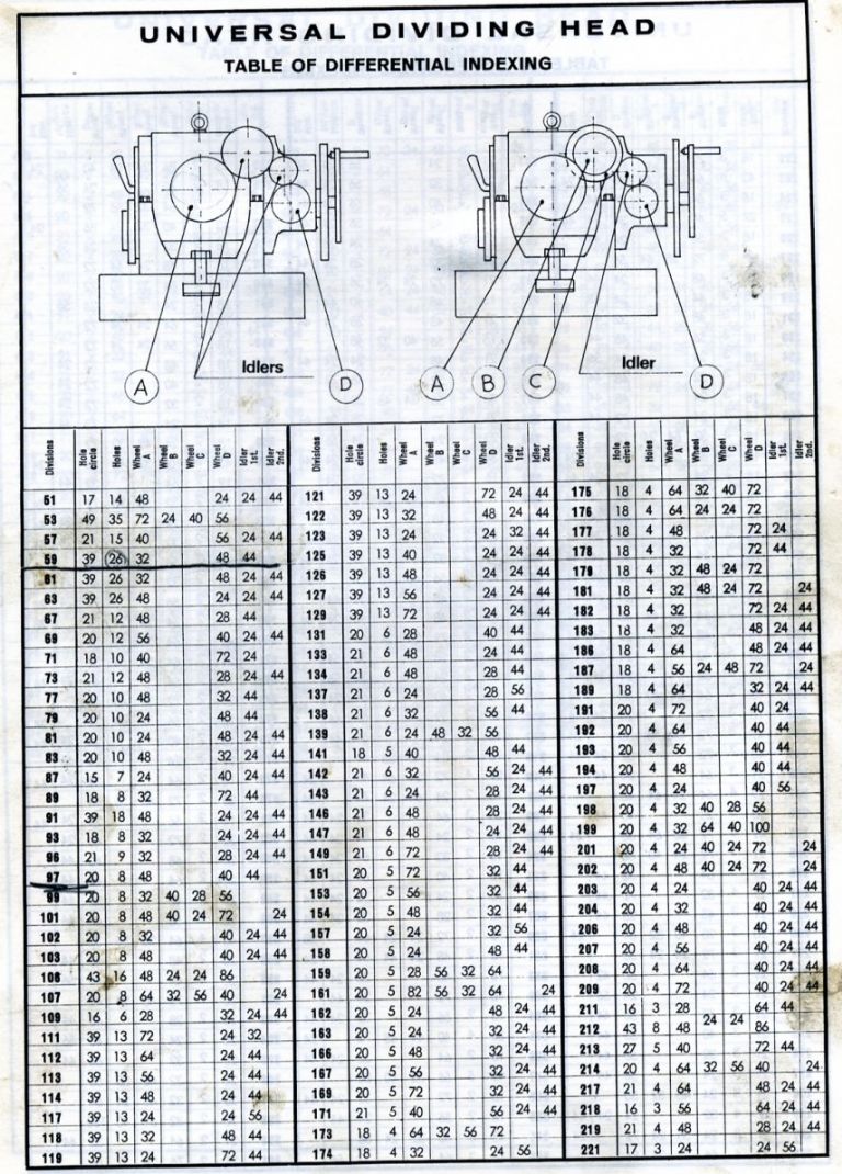
                That looks like and Enco, manual on the web. This is the table of primes they provide in it

                encodifdividing.jpg

                I'm pretty sure that I have seen an arrangement where the gearing is behind the plate rather than how this one and others are arranged.

                John

                #226724
                Engine Builder
                Participant
                  @enginebuilder

                  I have been following this thread with interest.

                  Can anyone state the formula for calculating the ratio of hob speed to number of gear teeth required.

                  I have cut worm gears using the free hob method but cannot see anywhere the details for hobbing with a proper hobbing tool.

                  #226736
                  Michael Gilligan
                  Participant
                    @michaelgilligan61133

                    Can't help you, Engine Builder … but I'm bumping this, in hope.

                    MichaelG.

                    .

                    P.S. This differential gear looks a bargain [if only we knew how to use it]

                    #226737
                    Gustav Thiesen
                    Participant
                      @gustavthiesen53240

                      To Engine Builder:

                      I'm not able to give you a formula. The mechanical way to do this is based on two arms:

                      1. you have a gear blank and the cutting hob

                      2. you have a dividing gear connected with a worm

                      The two are connected by an idler gear. If the dividing gear has 40 teeth, the cutting hob will also cut 40 teeth. If you want to have a 60 teeth gear, you must replace the simple idler gear by compound approach with two gears which gives a translation of 1,5. I hope you can understand what I mean, I have learned English more than fifty years ago.

                      #226743
                      Roderick Jenkins
                      Participant
                        @roderickjenkins93242

                        The simple answer, as I understand it, is that the hob rotates N times for each rotation of the blank, where N is the number of teeth to be cut. **LINK**

                        HTH,

                        Rod

                        #226747
                        Michael Gilligan
                        Participant
                          @michaelgilligan61133

                          Good link, Rod

                          … and the external PDF linked at the foot of that page is excellent.

                          MichaelG.

                          #226750
                          Bazyle
                          Participant
                            @bazyle

                            Correction to my earlier post. The 'very big gear' is probably directly keyed to the hob shaft not the sleeve. Makes more mechanical sense but doesn't change the operation of the device.

                            Slight clarification of Gustav's statement "If the dividing gear has 40 teeth, " that is the worm you see driving the blank. So formula is (desired number of teeth)/worm = (ratio of change gears on the banjo) You can use the link MG gave to calculate ratios.

                            Is anyone else thinking about the calculations for the differential which seems a bit less straight forward than differential dividing (which doesn't incorporate a differential and should be called 'difference dividing&#39?

                            It seems to me there are 2 gear train ratios, A and B both incorporating a common worm to complicate things that must satisfy the differential equation (Target gear) = 2A-B and probably A-B < 10 to stop the diff from spinning like crazy. The equations have to be exact not the usual 'near enough' to a few seconds of arc as for simple dividing tricks and metric thread calculations.

                            #226785
                            Engine Builder
                            Participant
                              @enginebuilder

                              OK as I see then, with a single start hob, the hob rotates one revolution for each tooth in the wheel being cut.

                              For a 2 start hob the hob rotates the number of teeth x 2, ie twice the speed.

                              Am I reading this correctly?

                              #226798
                              Ajohnw
                              Participant
                                @ajohnw51620

                                The aspect I find odd about home built hobbing machine is why apart from the challenge. My initial interest was down to the cost of gear cutters, not that hobs were cheap really but one does all. Hobs do appear to be cheaper now but the usual cutters can be too. In practical terms as some of the books mention for home use often a reduced set is more than adequate.

                                I'm curious. The home built one still has to fed etc by hand so I don't see the advantage over the Thomas approach for being able to cut prime tooth counts. Another plate could be used instead of a dial if time is important. A 127T gear would need nearly 19 turns per tooth with his set up. It divides into the low arc second range.

                                John

                                #226823
                                Gustav Thiesen
                                Participant
                                  @gustavthiesen53240

                                  To Engine Builder:

                                  If use a 40 teeth gear as index gear the hob will cut 40 teeth in the blank with one revolution. This is because of the coupling by the idler gear. If I change the idler gear by two gears on the same stud, which will deliver a translation of 1,5 you will get 60 teeth by one revolution. But these teeth are not complete, it will start with little notches which will be greater by feeding and get deeper by repeating passes.

                                  #227051
                                  Duncan Munro
                                  Participant
                                    @duncanmunro42894

                                    Hello there, I think this is the first time I've posted on here and is definitely the first day of my retirement so don't beat me up cheeky

                                    I've received an email from Gustav asking about the CES hobber and the differential gears and he has pointed me to this thread. When I get back home tonight I will dig out a spreadsheet I did some years ago in conjunction with a chap who had sight of a Jacobs hobber with differential gear. That will maybe help with his question in some way and provide some numbers to show how the primes ratios are formed from normal non-prime gearsets.

                                    Also some great replies on the thread on different ways to do things, and thinking outside of the box. If the 127T gear is for metric cutting on an imperial lathe it may be possible get some really good approximations using standard gears that can exceed the cutting accuracy of the machine without going to primes.

                                    As I'm getting incredibly lazy as I get older, rather than try and concoct some fancy solution to cut a gear I need but will only use once or twice, the 3D printer often gets a workout.

                                    I've attached some pictures, hope they show up. There's a couple of shots of a spare 60T gear on the Myford ML7 printed in ABS and a 127T gear for the same printed in PLA. I'll post again tonight when I've tracked the spreadsheet for the differential down.

                                    Regards,
                                    Duncan

                                    60T ABS gear

                                    60T ABS gear (close)

                                    127T PLA gear

                                    #227068
                                    Michael Gilligan
                                    Participant
                                      @michaelgilligan61133

                                      Welcome, Duncan !!

                                      MichaelG.

                                      #227105
                                      Gustav Thiesen
                                      Participant
                                        @gustavthiesen53240

                                        Many thanks Duncan!

                                        My special aim is not to make a 127 teeth gear. This is only one of the possibilities. My main target is to build up a hobbing machine, which should be able to cut prime number gears to. One reason for this is, that I have made a dividing head last year. Because it should also manage prime numbers, i made a compound dividing head. But when it was finished i saw that the handling was prone to errors. So I have transformed the construction to a differential dividing head. I had to cut 12 gears for this. I made them by poor mans hobbing method. To facilitate and to get better results I want to make this machine.

                                        #227113
                                        Bazyle
                                        Participant
                                          @bazyle

                                          John, the hobber does have an auto feed option if you look at the gears behind the worm driving the blank.

                                          Duncan, Great to see a practical ME use of printing. Of course a printer is a lot of trouble and expense to make so perhaps on a par with a hobber. But lots of whirling gears – got to be a winner.

                                          Had a look at the gear trains for making 127 and one option is 125 & 126, but for 126 you need a 63 prime. So you can make a 63 using 60 and 57 – oh dear another prime and so it goes on.

                                          #227231
                                          Bazyle
                                          Participant
                                            @bazyle

                                            Looking around the professional gear hobbers it appears they often don't have a differential. Instead they may knock up a quick prime as required on a dividing head then use it to give the exact ratio. They are of course into mass production so worth the effort.
                                            Their next option is to find a close, very close, approximation perhaps using 6 or 8 change gears to get an error with 7 or 8 zeros after the decimal point. This will give a slight progressive 'creep' out of sync. However this can be compensated by moving the hob ever so slightly along its axis using another set of change gears.
                                            Even with a differential it may not be spot on. The errors in the two trains can be arranged with one + and one – to partly cancel out.

                                            It is much easier with computers now but in the past you could get tables with eg 14000 ratios from gear sets listed.

                                            #227234
                                            John Haine
                                            Participant
                                              @johnhaine32865

                                              Umm… 9×7=63?

                                              Posted by Bazyle on 26/02/2016 17:39:50:

                                              John, the hobber does have an auto feed option if you look at the gears behind the worm driving the blank.

                                              Duncan, Great to see a practical ME use of printing. Of course a printer is a lot of trouble and expense to make so perhaps on a par with a hobber. But lots of whirling gears – got to be a winner.

                                              Had a look at the gear trains for making 127 and one option is 125 & 126, but for 126 you need a 63 prime. So you can make a 63 using 60 and 57 – oh dear another prime and so it goes on.

                                              #227240
                                              Bazyle
                                              Participant
                                                @bazyle

                                                blush

                                                #227249
                                                Ajohnw
                                                Participant
                                                  @ajohnw51620

                                                  smiley I seem to recollect that on Myfords the 63T means no need for the 127. Pitches with very very tiny errors.

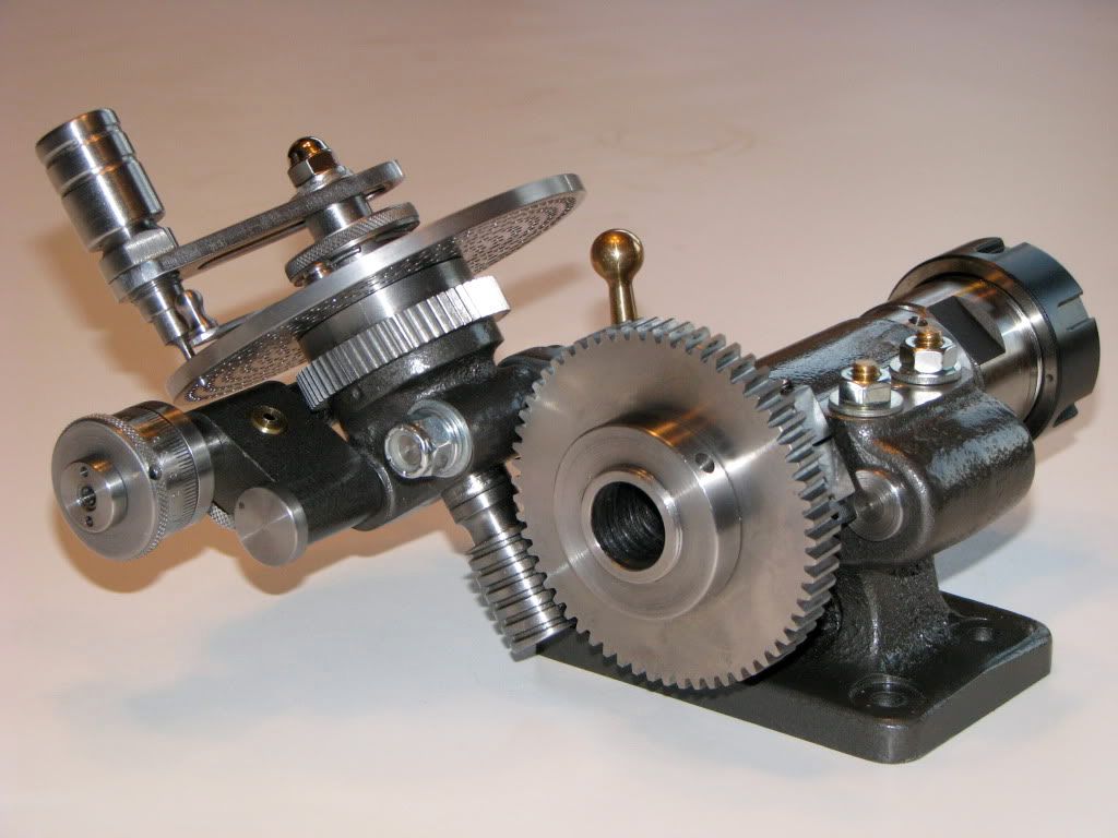
                                                  More for others that might be reading the thread. This is G Thomas's solution

                                                  As is often the case with these sort of designs all can be made on a Myford but the worms and wheels are usually bought. His BIG thick book goes through making it pretty thoroughly. Some people would buy the plates too. It's interesting to note that who ever made this one may have stuck to a long plain hole through the spindle of a size that also accepts the collet chuck. The short bar at the side is for a centre. One could be made based around a suitable small tailstock or fabricated.

                                                  My one by Dore or Westbury has a 2 morse socket and a myford spindle nose on it. Fine but if I want to use the hole I need something with 2 morse on it – a pain to make. A plain diameter mandrel is easy.

                                                  John

                                                  Edited By Ajohnw on 27/02/2016 15:48:44

                                                  #227252
                                                  Ajohnw
                                                  Participant
                                                    @ajohnw51620

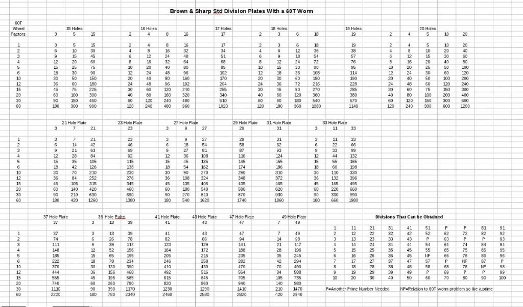
                                                    63 teeth isn't a problem with the plates Brown and Sharp came up with which gives these with 60T worm wheel. They were intended for 40T. I would have thought any design of plate would need the same base primes.

                                                    divisionsbandstandardplates.jpeg

                                                    I mentioned B&S because I noticed some Vertex stuff with parts I could use that also had plates but I wondered why they had departed from the usual hole counts so gave them a miss. I think the Cincinati design had yet more holes. Dore or Westbury went for fewer holes and no 63.

                                                    John

                                                    #227258
                                                    John Haine
                                                    Participant
                                                      @johnhaine32865

                                                      Since the question of the accuracy of digital dividing came up earlier in this thread I thought that I would see if I could measure how well my Ward / Myford divider does.

                                                      img_0554.jpg

                                                      The only way I have to measure angles conveniently is a Wixey gauge, so first I bolted an angle plate to my VH6 rotary table, set vertical on the mill table, and rotated the VH6 by various amounts, initially in 1 degree, then 10, then 45 degree increments. During this the mill drive was running as a little bit of vibration seems to make the Wixey behave better – I think it may have a very small amount of stiction.

                                                      The Wixey indication was never more than 0.1 degree out, and happily came back to zero after a complete rotation.

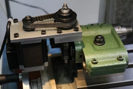
                                                      Then I set up the digital DH on the table, with a 4J holding a steel plate horizontal to take the Wixey, and repeated the measurements – with exactly the same results. Setting the DH up for 127 divisions, the angle readings agreed exactly with theory for each division at least to the resolution of the angle gauge (which is only 0.1 degree of course). My controller is set up for 4x microstepping, or 48000 steps per rev with the 60:1 worm drive in the Myford DH. Minimum theoretical angular resolution is 0.0075 degrees (with all the caveats about microstepping).

                                                      I don't think I'm going to worry about the accuracy of digital dividing for what I do.

                                                    Viewing 25 posts - 26 through 50 (of 83 total)
                                                    • Please log in to reply to this topic. Registering is free and easy using the links on the menu at the top of this page.

                                                    Advert

                                                    Latest Replies

                                                    Home Forums General Questions Topics

                                                    Viewing 25 topics - 1 through 25 (of 25 total)
                                                    Viewing 25 topics - 1 through 25 (of 25 total)

                                                    View full reply list.

                                                    Advert

                                                    Newsletter Sign-up