Thanks for the dimension confirmation, Jason. I obviously didn't look hard enough. I wasn't even sure that I was looking at the correct engine! I'll have a look after lunch which cutters I've got.
Unfortunately I've only got cutter sets for MOD 1 and MOD 1.5, so can't help after all. A quick draw-up in cad indicates a centre to centre distance of a shade more than that indicated by the dimensions on the frame drawing, as suggested by Jason.
If the original drawings are Imperial, it may be better to use DP gears if possible to avoid changing gear centres.
Jason has already told us by how much the centres need to alter when swapping between 32 DP and 0.8 MOD. It was 0.009". Even if you do nothing at all, it just means they wil run with a little more backlash. As most engines only run in one direction, this is not too much of an issue. If you do not want to change centres, you just turn up blanks that are 4 1/2 thou bigger on diameter, keep calm and carry on.
I've decided it's not appropriate to outline the mathematical basis of gears in what is essentially a practical thread.The only thing I will add is don't get your hopes up about Tracy Tools or Home and Workshop. When I was looking for a range of 5 and 6DP involute cutters for the gears on my traction engines they never seemed to have anything in stock. I was able to buy a job lot of cutters on Ebay, from the US, that covered all the spur gear tooth counts I needed, except one. For that I bought a new cutter from Victornet in the US.
Just to throw another option into the works if you do go down the 0.8MOD route or even if you stick with the original DP. Many of these full size open crank engines mounted the cam gear on an eccentric stud which allows for any one of many small errors that could creep in during manufacture of not only the gear but the frames also to be adjusted out by simply rotating the eccentric until a suitable running fit is found. Several of the hit & miss engines that I have made replicate this feature.
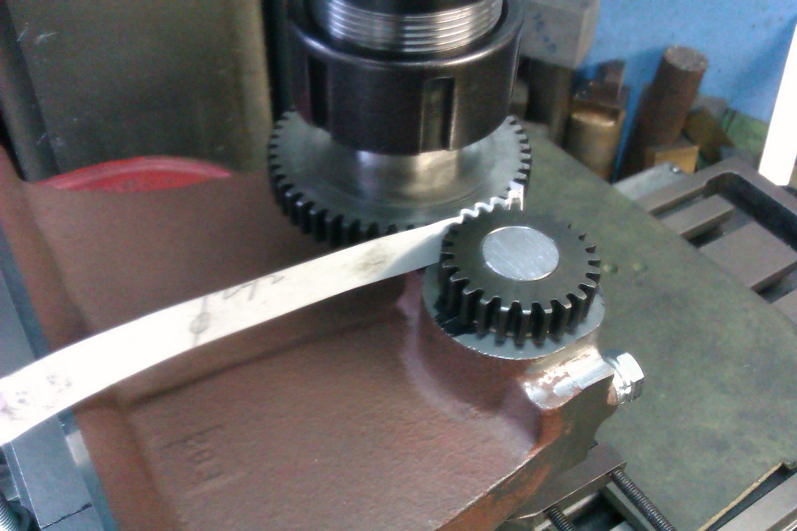
The other option that I mentioned earlier is depthing the gears where the two are placed in mesh with a strip of something thin between them to give slight backlash and the hole position taken from the actual ctrs of the gears. In this case I would keep the 0.290 dimension and allow any difference to be taken up in the 1.090" vertical direction as you can allow for any change simply you turning the adjustable tappet screw on the opposite end of the rocket shaft.
Here is one being done. Locate ctr of crankshaft bearing hole and zero DRO or handwheels. Pop in a temporary shaft and slip the smaller gear onto that. Out a bit of 1/4" dia material into your mill collet and the larger gear onto that. Move 0.290 in x and then adjust Y until the gears turn with the strip of paper between. Note the dro/handwheel reading and or lock the ways then remove gear, spot drill, drill reaming size and ream 1/4"
If you don't have a mill substitute a pointed bit of hardened 1/4" silver steel as a transfer punch for the larger gear to fit onto.
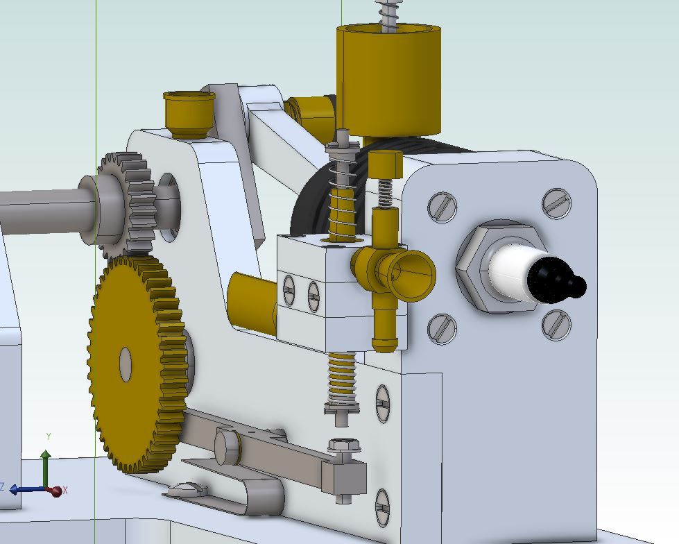
Drawing of the engine for anyone following along, you can just see the cam behind the larger gear. Cam pivot is 1.090" below the crankshaft and 0.290" towards the viewer. Diagonal of those two is the PCD of 1.128" which is 3thou over the PCD of 1.128" giving a bit of backlash to save binding.
Have a look at my video for making gear cutters and gears. You probably need an hour to make your first gear cutter on the mill using a vice and a cone drill or centre drill and and 2 hours to make the gear. I am sure you will do your next gear cutter and gear in half that time.
Thanks for the offer of lending me a arbor and cutters John. As previously said, I will buy the two gears for now and try to find a '3 to go with my #5 for future use. I will still probably buy the set of 0.8 mod as well as they will come in usefull for future projects.
Thanks for taking the time to show the photos Jason, They are very interesting.