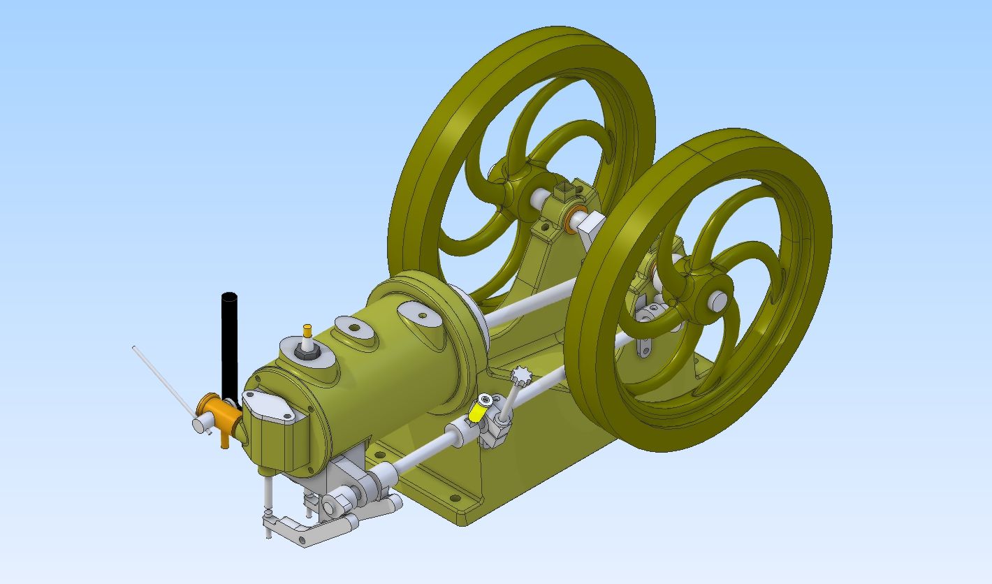
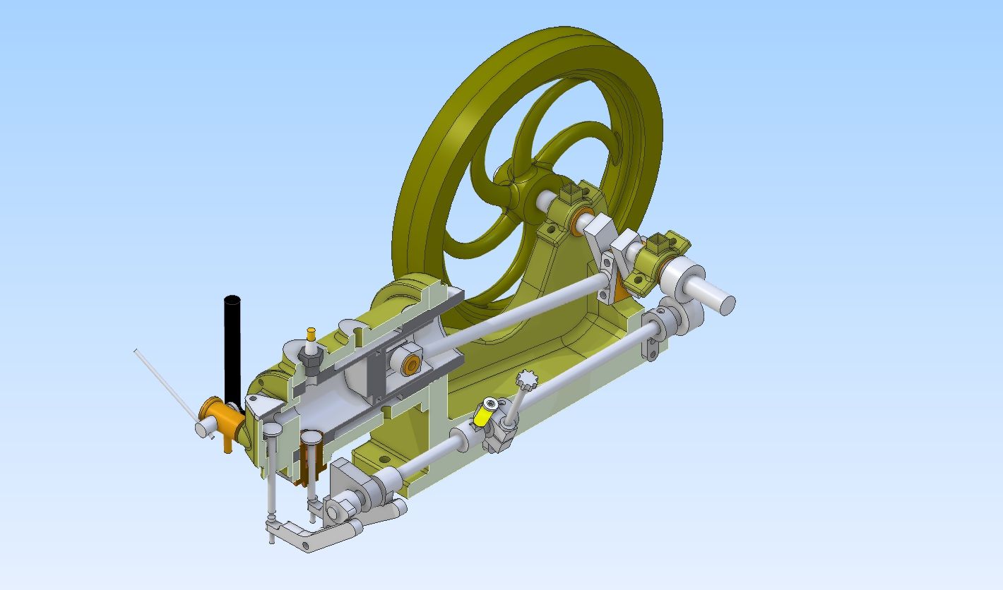
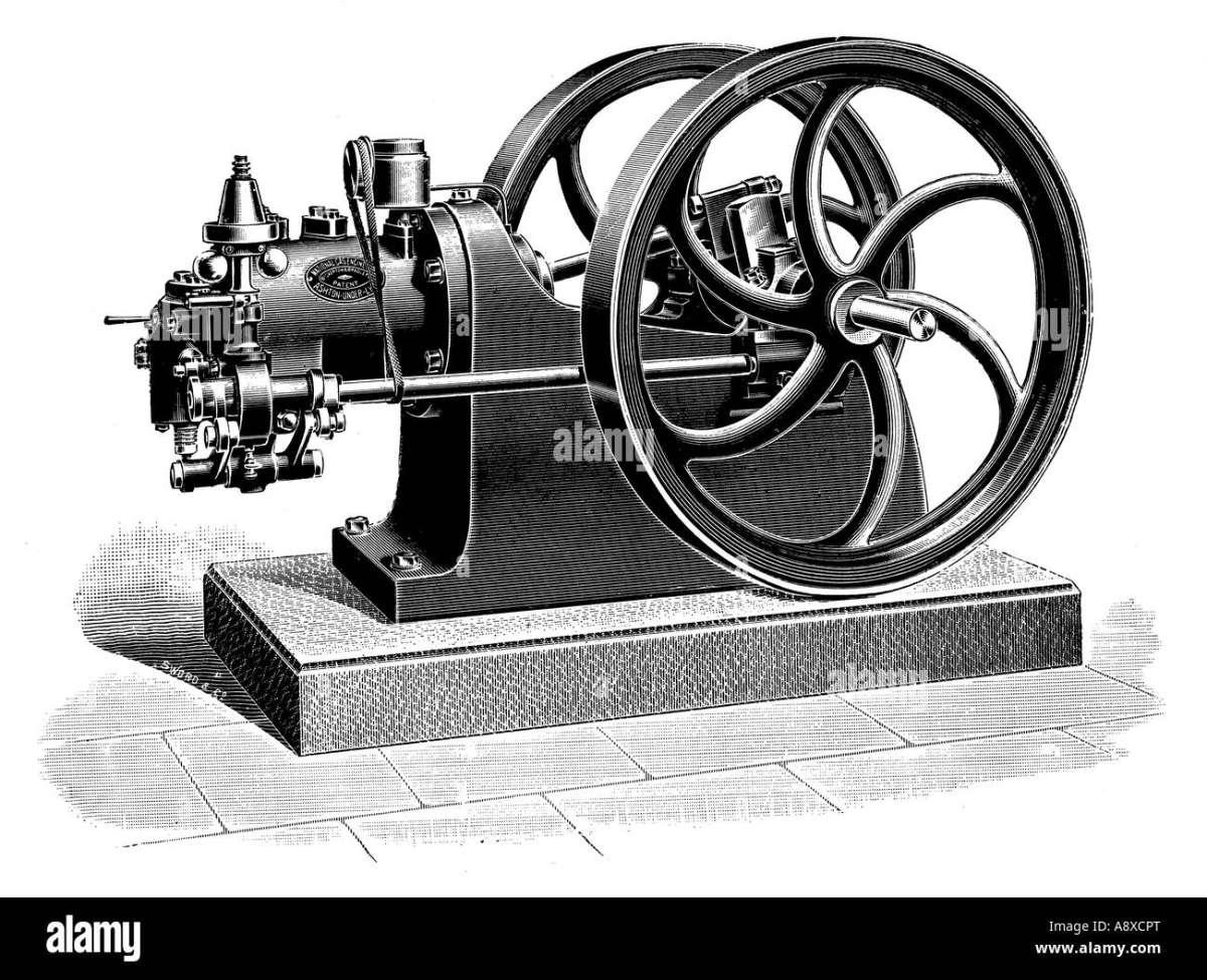
Gassie – national Gas Engine
Gassie – national Gas Engine
- This topic has 16 replies, 4 voices, and was last updated 23 May 2024 at 21:04 by
 Diogenes.
- Please log in to reply to this topic. Registering is free and easy using the links on the menu at the top of this page.
Latest Replies
-
- Topic
- Voices
- Last Post
-
-
Measuring a double Vee lathe bed Vee position
Started by:
Kim Garnett
in: General Questions
- 2
-
16 July 2025 at 16:22
Pete Rimmer
-
Drawings for constructing a Rolling Road
Started by:
Greensands
in: Help and Assistance! (Offered or Wanted)
- 6
-
16 July 2025 at 16:19
noel shelley
-
Silver steel crankshaft
1
2
Started by:
teamricky
in: Stationary engines
- 9
-
16 July 2025 at 16:14
JasonB
-
Herbert B drill information?
Started by:
Andrew Tinsley
in: Workshop Tools and Tooling
- 1
-
16 July 2025 at 14:23
Andrew Tinsley
-
How many spokes do I really need?
Started by:
Fulmen
in: Related Hobbies including Vehicle Restoration
- 7
-
16 July 2025 at 13:22
Vic
-
TurboCAD – Alibre File Transfers.
1
2
Started by:
Nigel Graham 2
in: CAD – Technical drawing & design
- 12
-
16 July 2025 at 13:14
JasonB
-
Electronic leadscrew pitching error
Started by:
paulg 1
in: Introduce Yourself – New members start here!
- 4
-
16 July 2025 at 12:19
JasonB
-
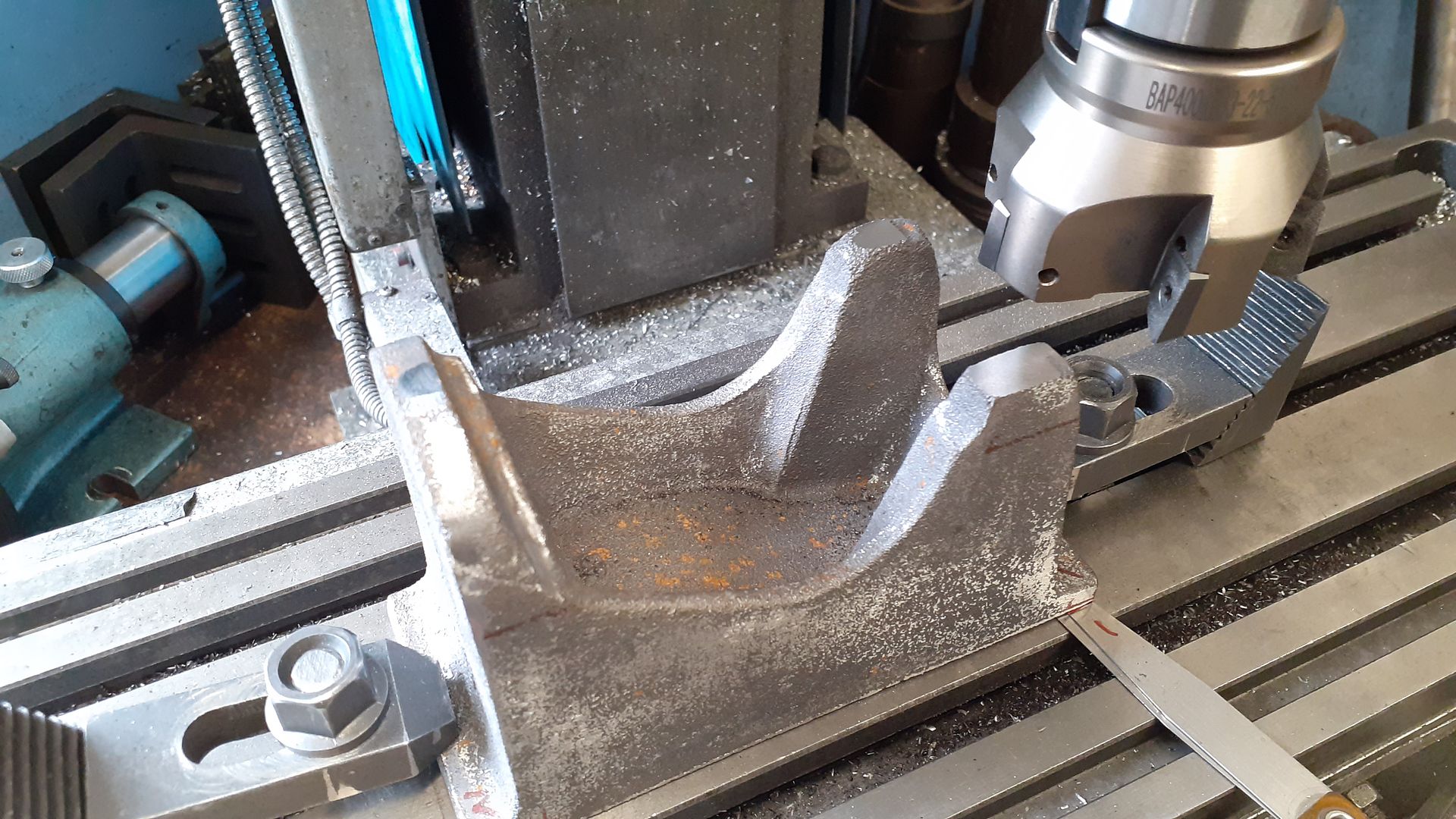
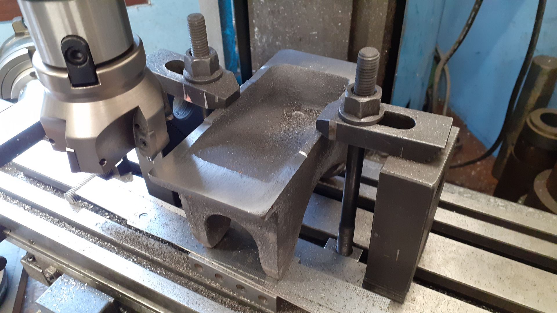
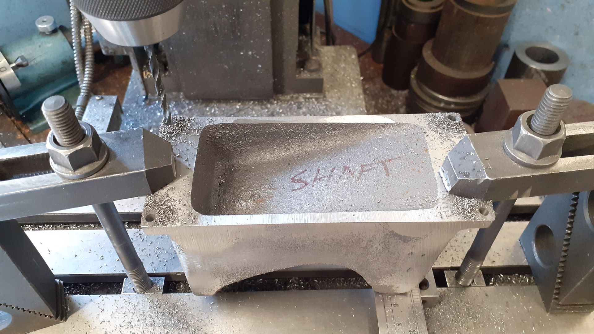
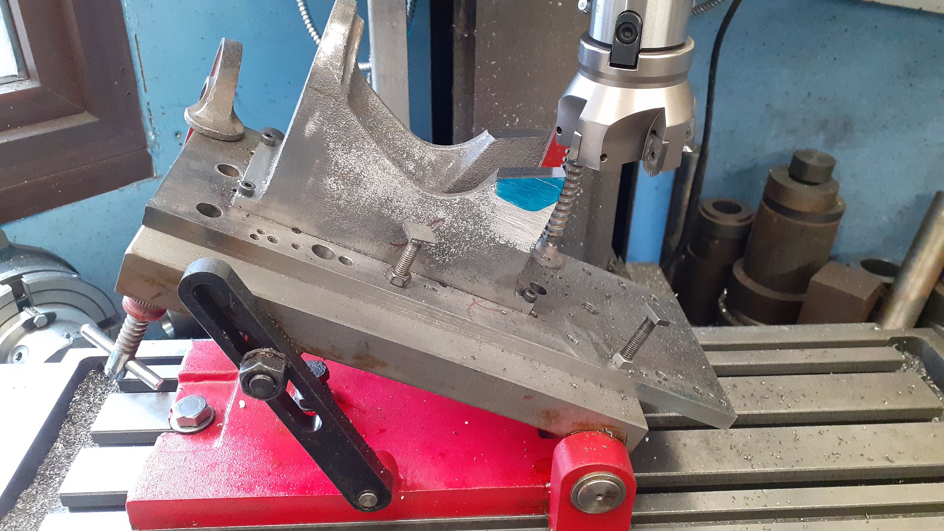
Advice to machine stationary engine base plate
Started by:
Greg H
in: General Questions
- 2
-
16 July 2025 at 12:13
Greg H
-
Boiler Design – issue 4765
1
2
…
8
9
Started by:
Charles Lamont
in: Model Engineer & Workshop
- 27
-
16 July 2025 at 10:22
noel shelley
-
I’m Under Pressure
1
2
Started by:
howardb
in: Related Hobbies including Vehicle Restoration
- 18
-
16 July 2025 at 10:21
Michael Gilligan
-
motor and switch wiring Myford ML7
Started by:
1957jmh
in: Workshop Tools and Tooling
- 7
-
16 July 2025 at 09:07
Les Jones 1
-
What Did You Do Today 2025
1
2
…
7
8
Started by:
JasonB
in: The Tea Room
- 33
-
16 July 2025 at 06:39
Diogenes
-
Suds tray sealant
Started by:
Dave S
in: General Questions
- 7
-
16 July 2025 at 01:31
cogdobbler
-
Error-Message of the day
Started by:
Michael Gilligan
in: The Tea Room
- 8
-
15 July 2025 at 20:42
Robert Atkinson 2
-
Sat nag
1
2
Started by:
duncan webster 1
in: The Tea Room
- 23
-
15 July 2025 at 20:02
Andy Stopford
-
Farm Boy
1
2
…
4
5
Started by:
Dalboy
in: I/C Engines
- 15
-
15 July 2025 at 19:52
Dalboy
-
“swedish iron”
Started by:
moonman
in: Materials
- 15
-
15 July 2025 at 16:52
Dave Wootton
-
Old plastic handled screwdrivers
Started by:
Dave Halford
in: Workshop Tools and Tooling
- 13
-
15 July 2025 at 14:49
Georgineer
-
Another Day … Another ScumBag
1
2
Started by:
Michael Gilligan
in: The Tea Room
- 15
-
15 July 2025 at 10:50
Graham Meek
-
Adjustable spanner thread direction
Started by:
jimmy b
in: Workshop Tools and Tooling
- 9
-
15 July 2025 at 08:25
Nicholas Farr
-
Screw cutting 1.25mm pitch on a Colchester Student.
Started by:
Kevin Nicholls
in: Manual machine tools
- 7
-
15 July 2025 at 06:53
larry phelan 1
-
Volt/amp meter
1
2
Started by:
duncan webster 1
in: Electronics in the Workshop
- 15
-
15 July 2025 at 06:15
Michael Gilligan
-
Variable DC power supply?
Started by:
Andrew Tinsley
in: Electronics in the Workshop
- 4
-
14 July 2025 at 17:27
Andrew Tinsley
-
Indicators – vehicle
Started by:
Speedy Builder5
in: Electronics in the Workshop
- 4
-
14 July 2025 at 06:02
Speedy Builder5
-
buying machine tools from aliexpress experiences?
Started by:
Jake Middleton-Metcalfe
in: Manual machine tools
- 16
-
14 July 2025 at 02:13
Neil Lickfold
-
Measuring a double Vee lathe bed Vee position
Latest Issue

Newsletter Sign-up
Latest Replies
- Measuring a double Vee lathe bed Vee position
- Drawings for constructing a Rolling Road
- Silver steel crankshaft
- Herbert B drill information?
- How many spokes do I really need?
- TurboCAD – Alibre File Transfers.
- Electronic leadscrew pitching error
- Advice to machine stationary engine base plate
- Boiler Design – issue 4765
- I’m Under Pressure

