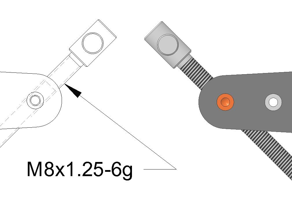
Fusion 360 Whitworth Threads
Fusion 360 Whitworth Threads
- This topic has 21 replies, 13 voices, and was last updated 30 August 2024 at 10:16 by
 John Doe 2.
Viewing 22 posts - 1 through 22 (of 22 total)
Viewing 22 posts - 1 through 22 (of 22 total)
- Please log in to reply to this topic. Registering is free and easy using the links on the menu at the top of this page.
Latest Replies
Viewing 25 topics - 1 through 25 (of 25 total)
-
- Topic
- Voices
- Last Post
Viewing 25 topics - 1 through 25 (of 25 total)
Latest Issue
Newsletter Sign-up
Latest Replies
- Easiest/cheapest source of R8 socket
- Even the Dealer Didn’t Know!
- How many spokes do I really need?
- Model Engine running just off a naked flame
- Please direct me to where I can find an engineer to do some bespoke work
- What Did You Do Today 2025
- Herbert B drill information?
- Which lubricator do I need
- Backplate studs
- William Hazeldine … Proving Machine


