Fusee Turning and Groove Cutting on my MYFORD

Advert

Fusee Turning and Groove Cutting on my MYFORD

Home Forums Clocks and Scientific Instruments Fusee Turning and Groove Cutting on my MYFORD

Viewing 17 posts - 1 through 17 (of 17 total)
  • Author
    Posts
  • #357092
    Noel Rieusset
    Participant
      @noelrieusset48142

      Having never turned a Fusee for a clock previously, I wanted to look into it before I made any attempts.

      I noted the two methods used by John wilding, and did not like them as I wanted to use a chain for drive not a twine etc. Therefore I needed a precise method of cutting the groove for the chain, maintaining constant depth.

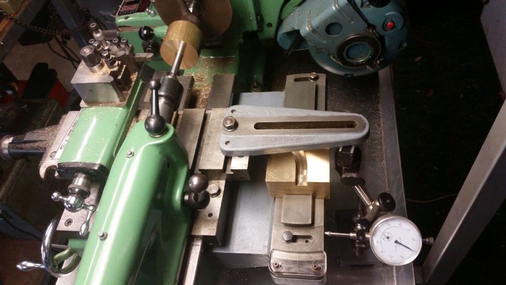
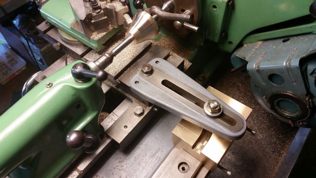
      I decided to adapt my taper turning attachment, replacing the sliding guide block with a fixed but adjustable radius cutting guide.

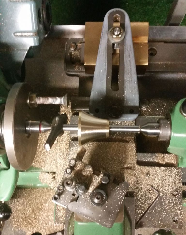
      I was very happy with the result, here are some photos to show what I did.

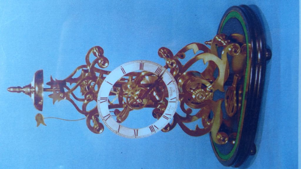
      1 Showing popular clock designed by John wilding

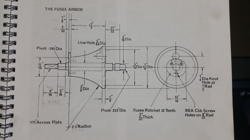
      2 The dimensions of the fusee from the book by John wilding.

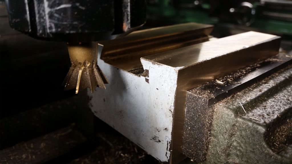
      3 Cutting the dovetail to mount the block onto the taper turning attachment.

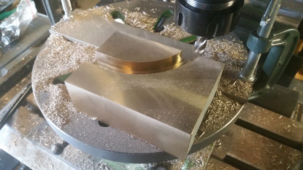
      4 Cutting the radius for the roller guide.

      5 Setting the attachment with the dial indicator.

      6 Showing the first few cuts of the fusee

      7 A overhead look of the cutting process.

      I have not cut the thread as yet because I have a fusee chain of 54” long, but I do not think it is long enough, I still have to find out the actual length, so if you have made one I would like to know please.

      elegant scroll frame skeleton clock j wilding.jpg

      elegant scroll frame skeleton clock fusee details.jpg

      fusee turning a cutting dovetail for guide.jpg

      fusee turning b cutting radius guide.jpg

      fusee turning c squaring copying slide to bed.jpg

      fusee turning d cutting radius.jpg

      Advert
      #3797
      Noel Rieusset
      Participant
        @noelrieusset48142

        Turning a Fusee Accurately

        #357096
        Roderick Jenkins
        Participant
          @roderickjenkins93242

          Noel,

          That's very neat. I shall file that use of the taper attachment away for future use.

          Thanks for sharing.

          Rod

          #357098
          Noel Rieusset
          Participant
            @noelrieusset48142

            Photo from above, now right side up….wink 2

            fusee turning d first cuts of radius.jpg

            #357102
            Noel Rieusset
            Participant
              @noelrieusset48142

              Overhead view of turning process

              overhead view of radius cutting.jpg

              #357106
              KWIL
              Participant
                @kwil

                How are you going to cut the groove?

                #357113
                Neil Wyatt
                Moderator
                  @neilwyatt

                  That's very neat and ingenious.

                  Neil

                  #357120
                  Anonymous

                    Neat implementation of what is essentially a simplified mechanical version of the hydraulic copy units found on industrial lathes. thumbs up

                    Of course what one really needs is a Myford Mini-Kop, anyone ever seen one?

                    I would imagine that the groove would be cut by normal screwcutting methods, but with the cross slide following the template. That's how I plan to make the BSP tapered threads on the blow down plugs for my traction engine boilers.

                    Andrew

                    #357179
                    Noel Rieusset
                    Participant
                      @noelrieusset48142
                      Posted by KWIL on 10/06/2018 13:04:11:

                      How are you going to cut the groove?

                      Hello,

                      I will be cutting the groove the same way as anyone would cut a thread.

                      I usually turn the spindle by hand keeping the leadscrew engaged.

                      Turning the radius I used the power feed, and the finish is perfect.

                      As I said above I am going to use a chain to drive the fusee, however at this stage I do not know its length,

                      so still have to order the chain, until I do I cant cut the groove until I know the width of the chain.

                      #357198
                      Marcus Bowman
                      Participant
                        @marcusbowman28936

                        How about using a milling spindle mounted horizontally on centre height, and a ball end mill. That way, you should be able to use your taper cutting method and template and achieve constant depth while 'screwcutting' using a spindle-mounted handle to turn the spindle and gearing slowly enough to suit the end mill.

                        Marcus

                        #357200
                        Noel Rieusset
                        Participant
                          @noelrieusset48142
                          Posted by Marcus Bowman on 10/06/2018 23:05:15:

                          How about using a milling spindle mounted horizontally on centre height, and a ball end mill. That way, you should be able to use your taper cutting method and template and achieve constant depth while 'screwcutting' using a spindle-mounted handle to turn the spindle and gearing slowly enough to suit the end mill.

                          Marcus

                          Hello Marcus,

                          I guess I could do that, however I do not think I would have enough room on the cross slide, as I am holding between centers and have the tail stock close.

                          The chain groove is approx. 0.050" wide, so I think a single point tool would do the trick, I can produce one easy on my tool & cutter grinder, less chatter possibility also.

                          #357204
                          Sam Stones
                          Participant
                            @samstones42903

                            Hi Noel,

                            Although I’ve only built one clock, there are clever people who contribute here that will offer you a great deal of help.

                            However, I can’t resist mentioning that the 2” radius nominated for the fusee  does not compensate for the variation in spring output (Mr Wilding’s shows 2.2” radius). If you are looking for good timekeeping, you may have to carry out some torsion test beforehand.

                            You can see from my crude graph(s) at the bottom of this page the sort of variability which resulted.

                            **LINK**

                            By the way, I used a similar cam approach on my ML7, by way of parts from the taper turning attachment.

                            On the same page of photographs, you can see that I first used fishing line (yellow). It broke after three years, so I replaced it with twisted steel.

                            A chain would look even better.

                            If you are a contributor to Model Engineer, I wrote a seven-part article about building John Stevens’ skeleton clock.

                            It commenced with #4526 dated 22nd Jan 2016.

                            Good luck,

                            Sam

                            Edited By Sam Stones on 11/06/2018 01:28:05

                            #357207
                            Noel Rieusset
                            Participant
                              @noelrieusset48142
                              Posted by Sam Stones on 11/06/2018 01:25:01:

                              Hi Noel,

                              Although I’ve only built one clock, there are clever people who contribute here that will offer you a great deal of help.

                              However, I can’t resist mentioning that the 2” radius nominated for the fusee does not compensate for the variation in spring output (Mr Wilding’s shows 2.2” radius). If you are looking for good timekeeping, you may have to carry out some torsion test beforehand.

                              Hello Sam,

                              Thank you for your comments.

                              I do realize the radius of the fusee is not perfect.

                              My future intentions are.

                              I am waiting on a book which will give me the ability to calculate fusee curves.

                              I will then produce the curve and cut it into my guide with a CNC. Then I will be able to produce the exact curve.

                              Thank you for the link and information, I will have a look with interest.

                              Cheers

                              Noel

                              #357209
                              Noel Rieusset
                              Participant
                                @noelrieusset48142

                                Hi Sam,

                                I just had a look at your Clock, very nice.

                                Thank you for the posting, I thing it will be my next clock.

                                I will check to see if the book is still available.

                                Thank you

                                Noel

                                #357210
                                Sam Stones
                                Participant
                                  @samstones42903

                                  Hi Noel,

                                  Those were quick replieslaugh.

                                  I'm only too pleased to help where I can. Especially having so much help from others on this site.

                                  John Stevens' skeleton clock article commenced in Model Engineer in Jan '72 and ran for five editions. I started cutting brass for it in about '73.

                                  However, I haven't seen his article in book form.

                                  Regards,

                                  Sam

                                  #357376
                                  Noel Rieusset
                                  Participant
                                    @noelrieusset48142

                                    Any curve can be cut with this method.

                                    With a fusee this is my first try, and I know the radius is only an average of the correct curve.

                                    With this method, the true curve of the fusee (Or any other curve) can be calculated.

                                    The pattern can then can be reproduced with the aid of a CNC machine, put on to a lathe (Myford)

                                    and cut exactly the way the calculations show.

                                    Cheers

                                    Noel

                                    #357391
                                    Journeyman
                                    Participant
                                      @journeyman

                                      Nice job Noel. I wonder if the pattern can be 3D printed? Much easier and probably quicker than CNC. Even PLA would probably be hard enough and stiff enough for a limited number of runs especially if glued to a metal backplate. Nylon would likely be better but slightly more difficult to print.

                                      John

                                    Viewing 17 posts - 1 through 17 (of 17 total)
                                    • Please log in to reply to this topic. Registering is free and easy using the links on the menu at the top of this page.

                                    Advert

                                    Latest Replies

                                    Viewing 25 topics - 1 through 25 (of 25 total)
                                    Viewing 25 topics - 1 through 25 (of 25 total)

                                    View full reply list.

                                    Advert

                                    Newsletter Sign-up