Further Adventures with the Sieg KX3 & KX1

Advert

Further Adventures with the Sieg KX3 & KX1

Viewing 25 posts - 176 through 200 (of 383 total)
  • Author
    Posts
  • #464144
    Sarah F
    Participant
      @sarahf
      Posted by JasonB on 12/04/2020 10:10:52:

      Sarah, going by what Adam (Son of the late John Stevenson) said both mine and Ian's are connected by USB so our speeds are controlled differently to your earlier parallel port machine which is why I have nothing on the spindle screen and would think Ian's would be the same though he only showed the X axis..

      Hi Jason,

      I think Adam said the timing was controlled differently, but are the Steps Per, Velocity and Acceleration still adjustable from the Motor Tuning screen? I've been doing a lot of reading on line but not found enough out unfortunately.

      I've got a friend getting me some aluminium offcuts from work which will be very useful for mounting bit to 😊

      Regards,

      Sarah

      Advert
      #464147
      Adam Stevenson
      Participant
        @adamstevenson91624

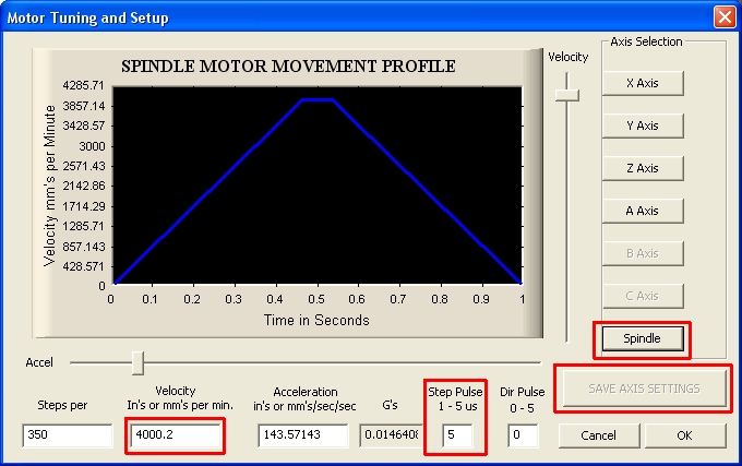
        Hi Sarah, if you have a parallel (25 pin D connection) Then the pulse will matter as it is common on all motors, USB have in B type and us an internal timer to control the pulse.

        The SIEG needs about 5us step pulse for the spindle to drive the motor tacho controller, the Axis motor drivers will run on a smaller step pulse but as they are all the dame value setting it to 5us will be fine. Some computers even needed 6 or 7 depending on the motherboards.

        Below is the spindle tuning picture from the old web site for support, so are what the machines are set at and the one you need to change shown using the formula.

        (Required Vel) = [Required RPM] X [current Vel] / [Measured RPM]

        So if you are setting the speed to 1,000 and getting 1,234 RPM with the default 4,000 Vel you set it to 3241.49 Vel
        3241.49 = 1000 * 4000 / 1234

        #464153
        Adam Stevenson
        Participant
          @adamstevenson91624

          #464182
          Sarah F
          Participant
            @sarahf

            Hi Adam,

            What effect does varying the Steps per value? I can understand it's use with stepper motors, but not with a brushless motor.

            Regards,

            Sarah

            #464202
            Adam Stevenson
            Participant
              @adamstevenson91624

              It was found to be 350 for best results, the velocity is the one important for the spindle. Lots of testing was done with these machines and each one from Arceuro was calibrated to allow a quicker setup by the users.

              The actual values are regardless it is the ratio between them that matters. Think that for each 360º the computer sends steps, it is not just how many steps are sent but how fast the amount are sent too. But we are not sending steps but a Voltage that the controller uses to drive the motor at a set speed, they is also a in-built tacho that will increase or decrease the current to keep the speed constance. So at the end it is not the number of steps sent per revolution but the rate at which they are sent. So we pick a nice number and then how fast we send them and balance the ratio between them, in this case 350 x 4,000 or 35 x 40,000 or 3,500 x 400. The computer will have limits so we picked the mid ground that most PC's would work with.

              Edited By Adam Stevenson on 12/04/2020 13:16:52

              #464204
              Ian Johnson 1
              Participant
                @ianjohnson1

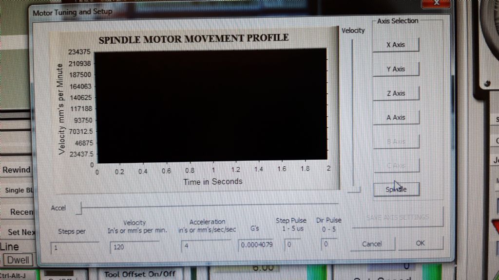
                Hi Sarah I just realised that I gave you the Z axis motor info not the spindle motor info duh!

                So here is my spindle motor info for my KX1

                Steps per = 1

                Velocity = 120

                Acceleration = 4

                G's = 0.0004079

                Steps pulse = 0

                Dir pulse = 0

                Same caveats apply, they work okay on my machine and I am useless on computer stuff!

                20200412_131254.jpg

                #464231
                Sarah F
                Participant
                  @sarahf

                  Hi Adam,

                  Thank you so much for your help 😊 I'll spend a bit of time tomorrow putting in your values and fine tuning to get the Spindle rpm matching rpm requested. I understand whay you said about ratios of Step per and Velocity, but still can't rationalise the big variance in the different machine's values, however as long as it works 😊

                  Still waiting for the new 6mm cutters, I've got 4 flute cutters, but I'll be patient and wait. Many project's to do lincluding trying to machine some 2mm carbon fibre sheet.

                  Thanks again,

                  Sarah

                  #464234
                  Former Member
                  Participant
                    @formermember32069

                    [This posting has been removed]

                    #464372
                    Sarah F
                    Participant
                      @sarahf
                      Posted by Adam Stevenson on 12/04/2020 13:13:25:

                      It was found to be 350 for best results, the velocity is the one important for the spindle. Lots of testing was done with these machines and each one from Arceuro was calibrated to allow a quicker setup by the users.

                      The actual values are regardless it is the ratio between them that matters. Think that for each 360º the computer sends steps, it is not just how many steps are sent but how fast the amount are sent too. But we are not sending steps but a Voltage that the controller uses to drive the motor at a set speed, they is also a in-built tacho that will increase or decrease the current to keep the speed constance. So at the end it is not the number of steps sent per revolution but the rate at which they are sent. So we pick a nice number and then how fast we send them and balance the ratio between them, in this case 350 x 4,000 or 35 x 40,000 or 3,500 x 400. The computer will have limits so we picked the mid ground that most PC's would work with.

                      Edited By Adam Stevenson on 12/04/2020 13:16:52

                      Hi Adam, I now understand what you meant about the ratios of Step per and Velocity.

                      Your 'Step per' multiplied by 'Velocity' figures are approximately double those of mine. I put your Step per x Velocity in to my machine and the sure enough the rpm doubled! A requested 2000rpm shot up to over 4000rpm! So presumably I can either have my 100 x 6000 or modify yours to 350 x 2000 (plus a bit of twaekage). Is there any practical difference between the two?

                      The X, Y and Z axis seem fine at 5us Step Pulse, they just sound a bit different.

                      Thanks for your help and patience.

                      Sarah


                      Edited By Sarah on 13/04/2020 12:40:40

                      #464383
                      Adam Stevenson
                      Participant
                        @adamstevenson91624

                        You can use 100×6000 or 350×2000, it is the ratio that matters but once you pick a Step per keep that and the formula is simpler as you don't need to track two changing values like the X, Y, Z and A need.

                        (Required Vel) = [Screen RPM] X [current Vel] / [Measured RPM]

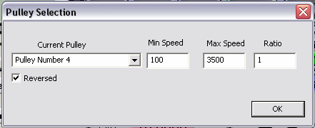
                        Once you get the 5,000 max done then you can change the pulley to 7000 max, I suggest not to put a high number as 7,000 is all you want and setting it to 100,000 max could then sending a 70,000 speed that can cause a massive load.

                        #464422
                        Sarah F
                        Participant
                          @sarahf

                          Hi Adam

                          All done 😊

                          Thanks again for your help. Spindle speeds are quite close to demanded speeds and I've spent the afternoon practicing some bits in foam before I cut in aluminium.

                          Regards,

                          Sarah

                          #464439
                          Sarah F
                          Participant
                            @sarahf

                            Hi Barrie,

                            Thanks for your post on milling carbon fibre, I've sent you a message with a few questions.

                            Regards,

                            Sarah

                            #464853
                            JasonB
                            Moderator
                              @jasonb

                              Hi Nick. yes I'm getting to like it, still won't be getting rid of the manual machines but the CNC does open up the options available and enable some projects that may not have seen the light of day be brought forwards.

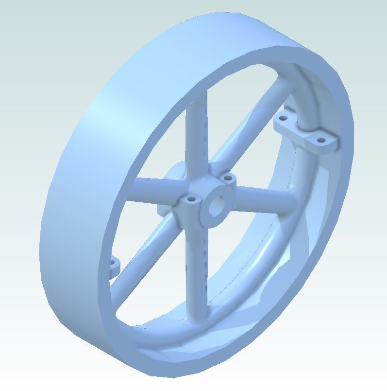
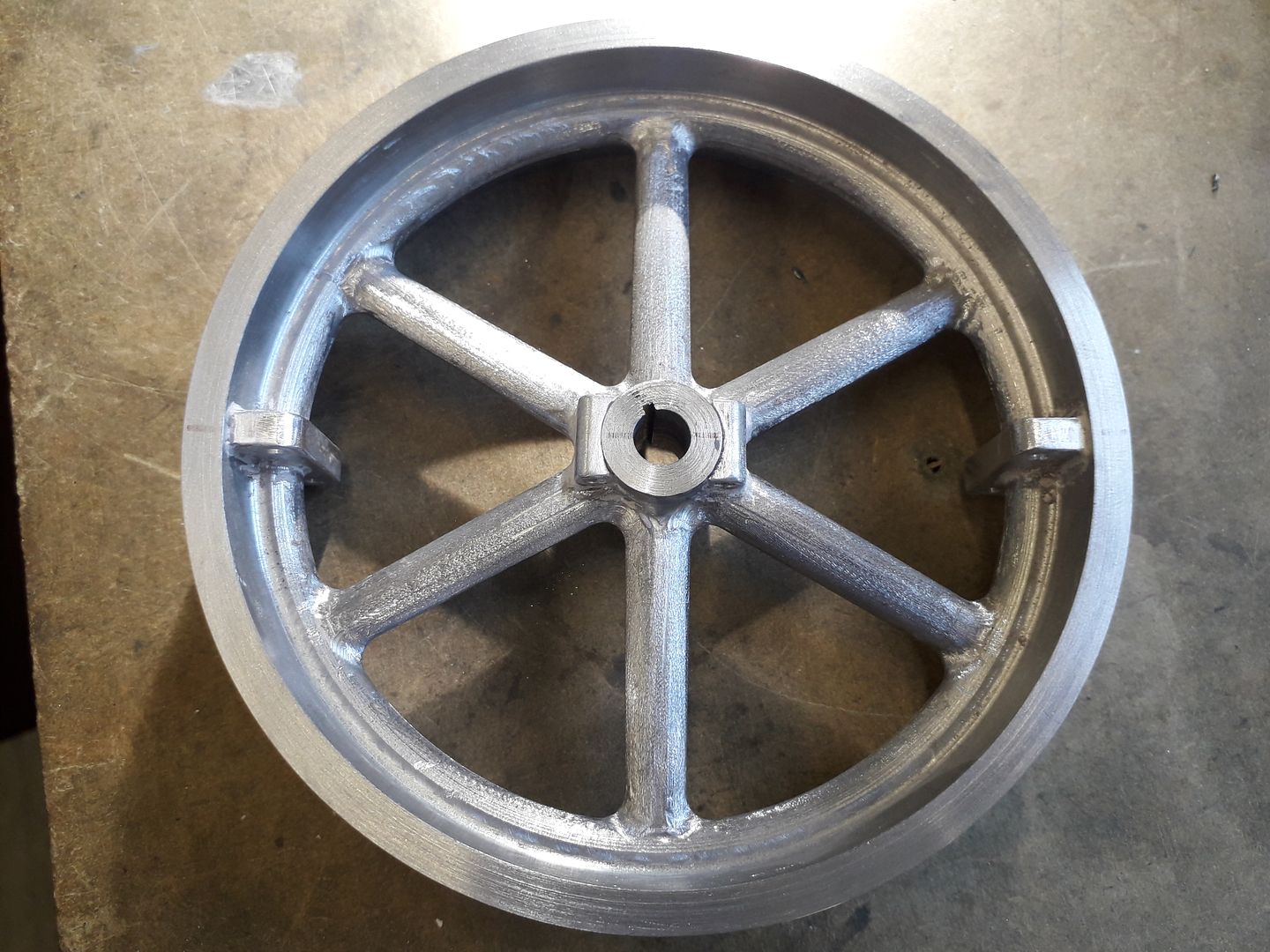
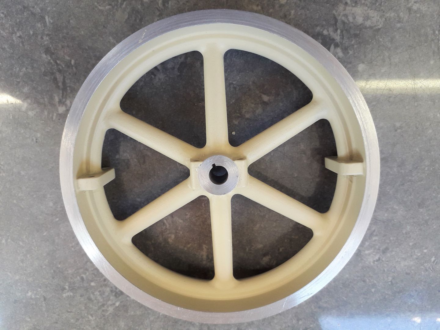
                              For the current engine that I'm working on I wanted a flywheel with quite a wide but thin rim and oval spokes tapering in width and thickness .

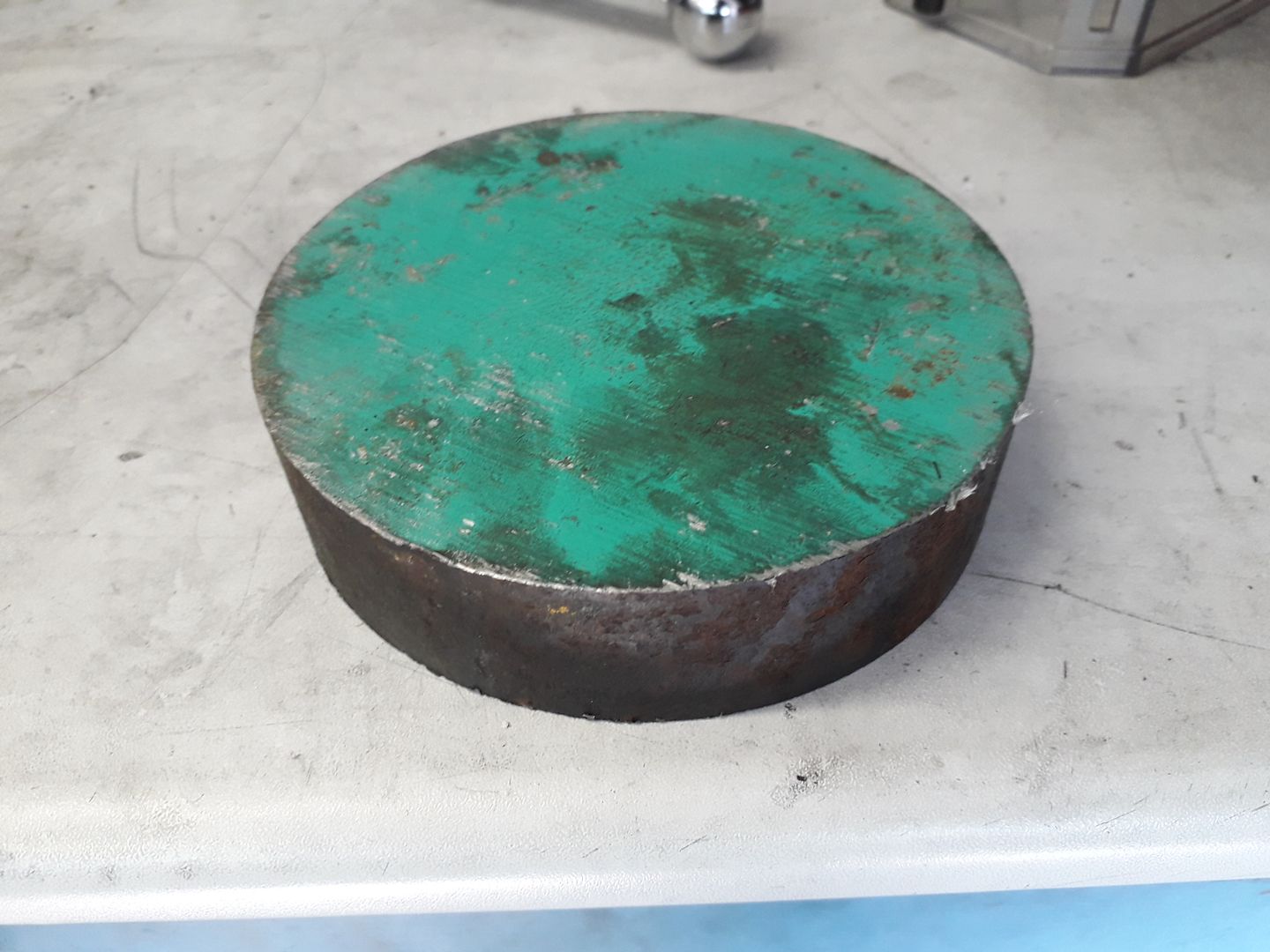
                              I have often used cast flywheels from other models but could not find anything to suit. Fabrication was an option but by the time I had sourced some thick wall tube, a disc to cut the spokes from and added something to beef up the hub area it worked out cheaper to go for the solid option so I ordered a 30mm length of 130mm diameter EN3 steel.

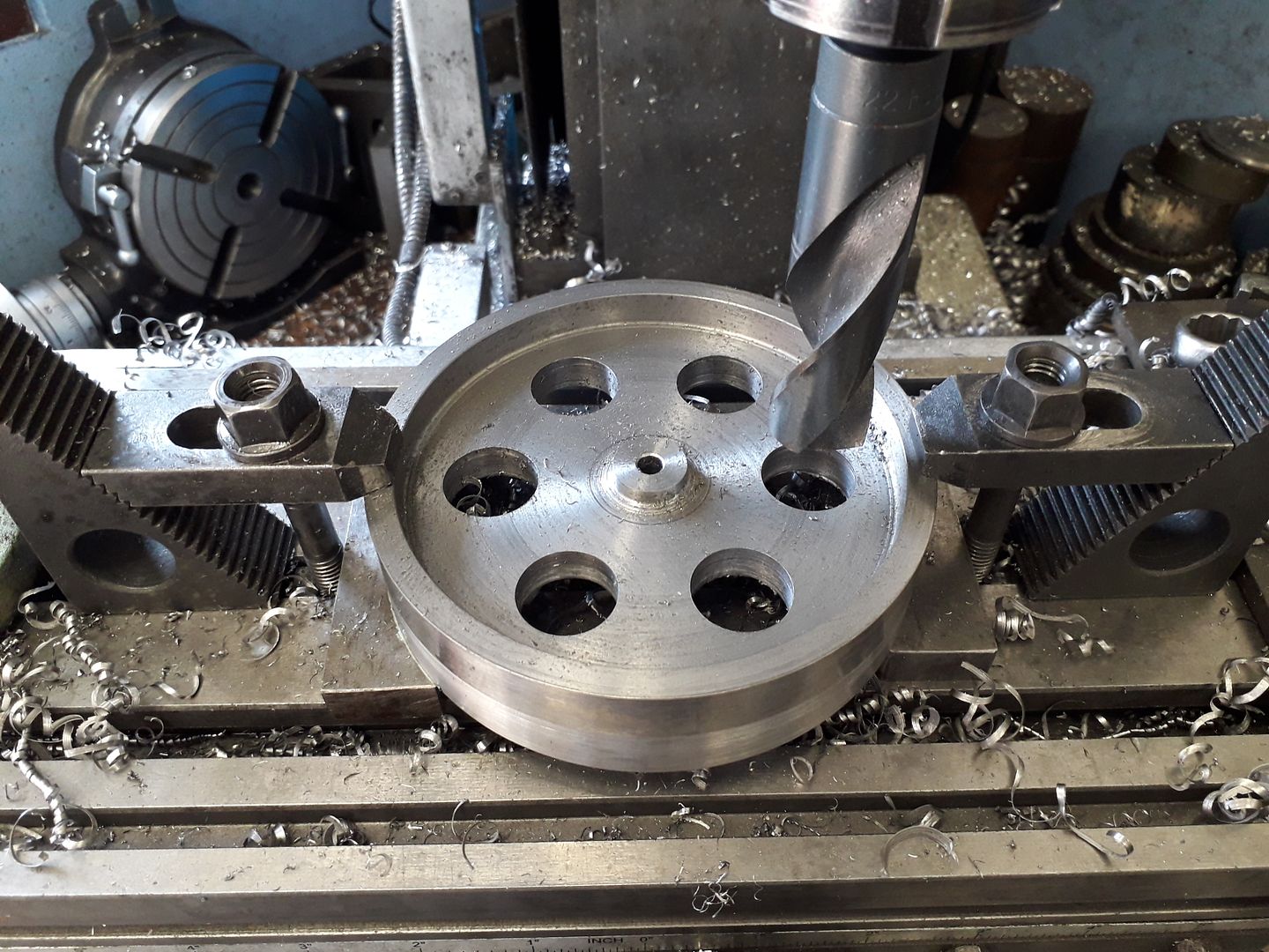
                              I decided to rough it out on the lathe and manual mill leaving material on all surfaces.

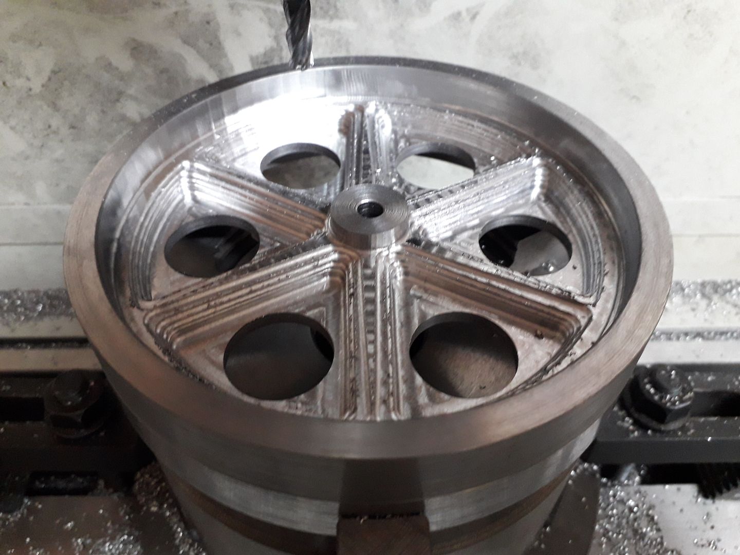
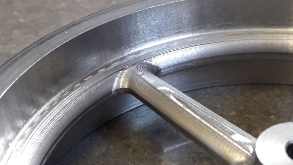
                              i did a dummy clearing program to mimic what I had done on the manual machines so that the CNC would not try and remove the metal again and then a clearing program was run starting at the height of the "disc" with a 1mm stepdown that left a finish like this

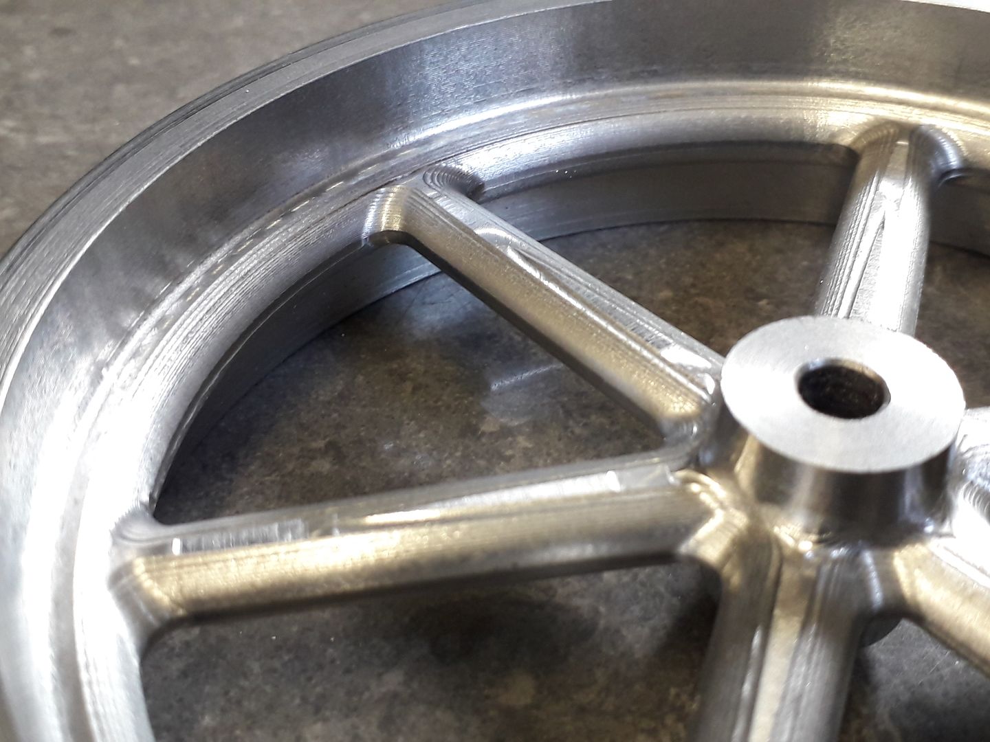
                              Then a finishing ramp with 0.2mm stepdown to give the draft angle to the inside of the rim and hub and then carry on down further to shape the spokes with a 6mm dia R1 tool

                              It then just needed a bit of fettling with the Dremel to blend the 0.2mm steps and I also added the bits to make it look like a 2 part flywheel.

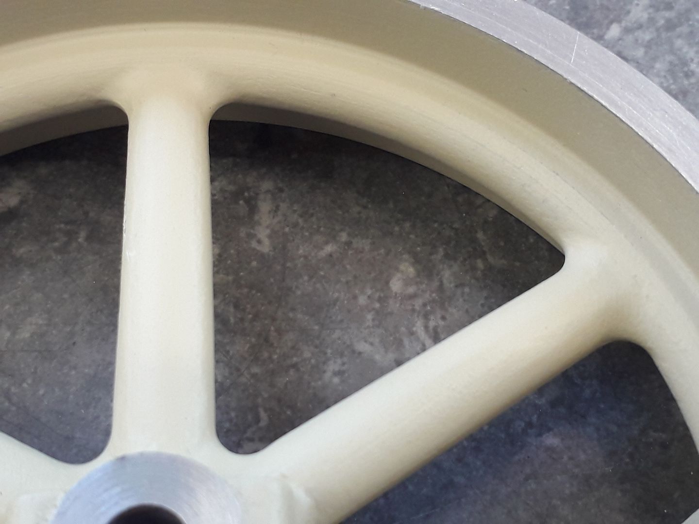
                              A couple of coats of filler/primer and it's ready for colour.

                              Looks like I won't be needing many castings in the future.

                              #464876
                              Ian Johnson 1
                              Participant
                                @ianjohnson1

                                That turned out very nice Jason how long did it take to machine?

                                And like you say who needs castings when you have a cnc?

                                Ian

                                #464881
                                Andrew Evans
                                Participant
                                  @andrewevans67134

                                  That looks great Jason – lovely job. Did you have any issue with the milling cutter going blunt part way through? Andy

                                  #464894
                                  Andrew Johnston
                                  Participant
                                    @andrewjohnston13878

                                    Looking good. thumbs up

                                    I might make one change. Using a 6mm ballnose cutter instead of a radius tip cutter would have given a better finish for a given stepdown, especially on the more vertical surfaces. Ideally one would vary the stepdown according to the slope of the work. Does Fusion360 have a command for scallop height rather than stepdown?

                                    Andrew

                                    #464909
                                    JasonB
                                    Moderator
                                      @jasonb

                                      That's interesting Andrew as it was the more horizontal surfaces that showed the 0.2mm stepdown most with the finish getting better the more vertical the surface became, this image should come up larger if clicked and shows that near the tops of the spokes the step was most obvious

                                      02 step.jpg

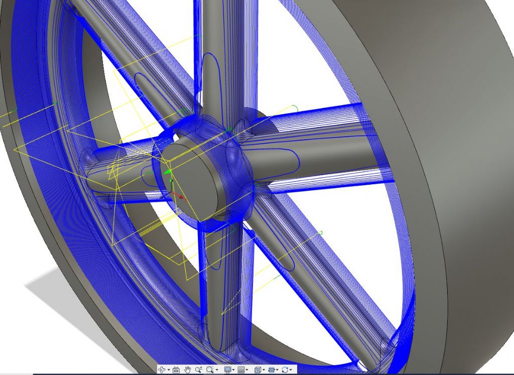
                                      One consequence of using the RAMP path is that the tool just drops 0.2 mm over the "loop" be that once around the inside of the rim or once around each triangular cutout without any other options. You can see below how the tool made very few passes (blue line is path of tool) over the top edge of the spoke resulting in that long triangle that can be seen in the photo above.. I could have divided the job up into say three heights and set a finer stepdown for that area at the top of the spokes and maybe more than 0.2mm for the first inside of the rim as that is almost vertical (3deg draft angle)

                                      ramp.jpg

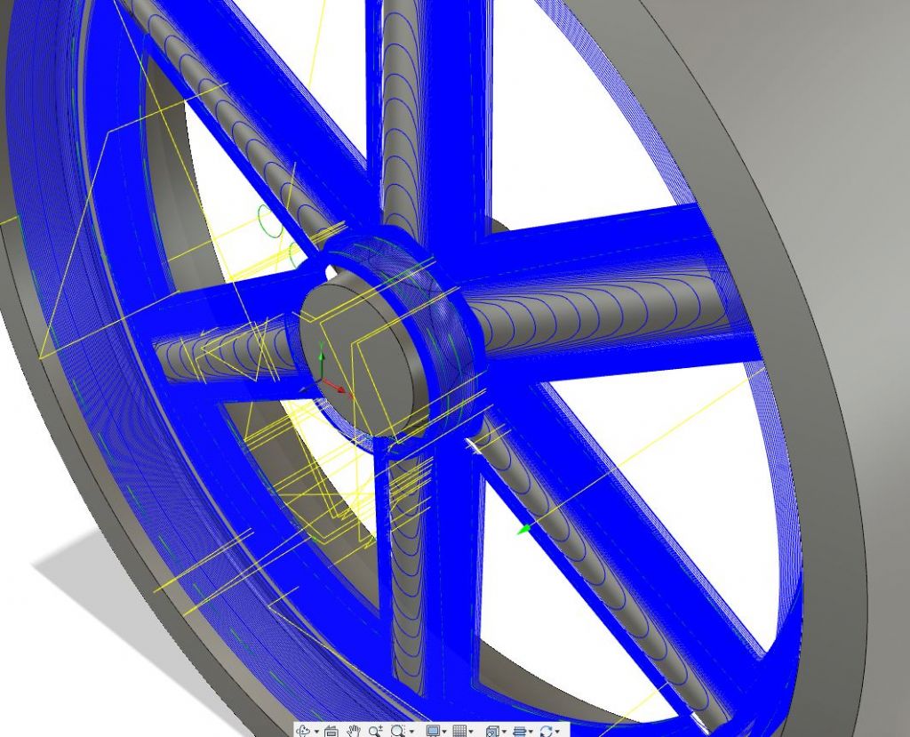
                                      Had I used the contour option where the tool moves around at one height then steps down then that has the facility to "detect shallow areas" and gives the option to set a different stepdown for those, as far as I can see there is not "distance between cuts". The pic below shows the greater number of passes over the shallow tops of the spokes when detection is enabled and set at 0.05mm stepdown. Only downside is it takes a lot longer to run and certainly longer than it took to Dremel the surface. Add to that the need to adjust feed for the slow moving middle of the ball nose cutter and it would be even longer I suppose if it was to be a bare metal surface then that would be the way to go but as it is supposed to be a painted "casting" then a bit of irregular hand finishing suits more.

                                      shallow.jpg

                                      #464921
                                      Former Member
                                      Participant
                                        @formermember32069

                                        [This posting has been removed]

                                        #464942
                                        blowlamp
                                        Participant
                                          @blowlamp

                                          In Fusion 360, Steep & Shallow toolpath strategy seems to give good results for this kind of job.

                                          Martin.

                                          #464962
                                          JasonB
                                          Moderator
                                            @jasonb

                                            Barrie, Martin

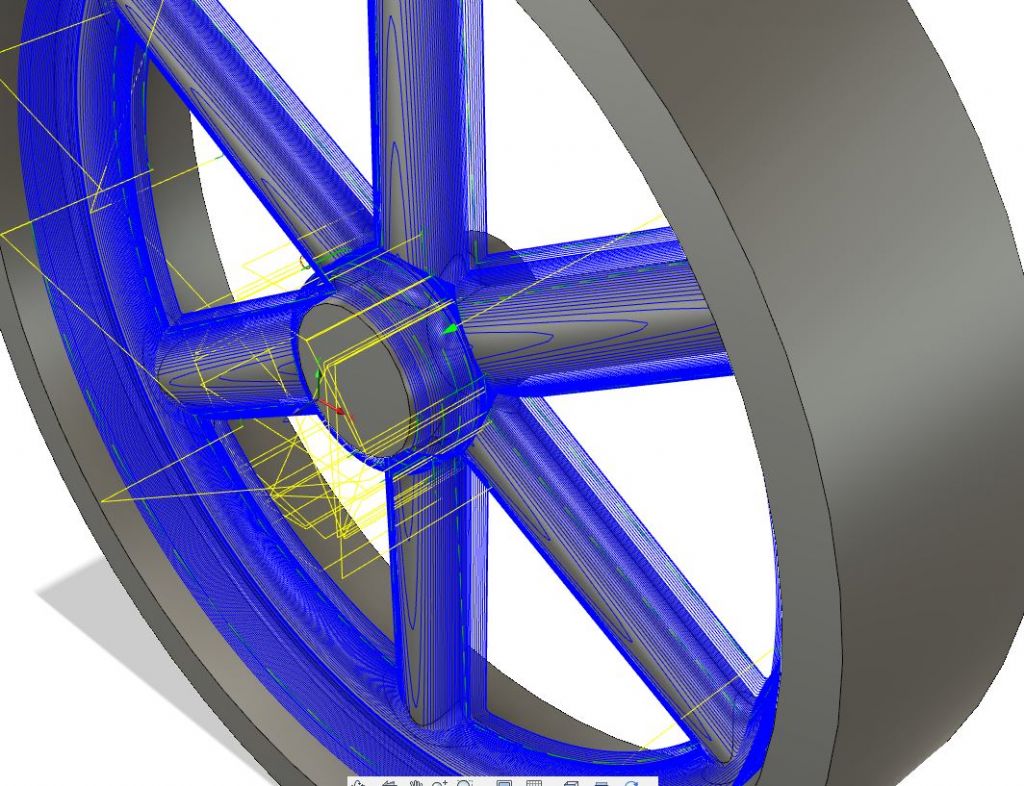
                                            Yes looking again there is the option to set a max stepover, pic below shows the effect of setting that at the same value as the stepdown which gives the path shown below which is somewhere between the two examples I posted above.

                                            step over max.jpg

                                            Fusion does have so many features that it takes a while to find them all, not helped by only using the CAM for a couple of items per month, with more use I'm sure I will become more familiar with it and not choose the Ramp option for parts like this well certainly not the spokes as it was ideal for the inner edge of the rim.

                                            Muzzer who now posts on MEM also mentioned about using a 3D model of the roughed out part as the stock which would have been useful as I could have set the six holes as entry points as it was I just used a steep ramp angle and large dia to save time as the tool ramped down into the metal it thought was there.

                                            #464971
                                            Ron Laden
                                            Participant
                                              @ronladen17547

                                              That is impressive Jason especially looking at the close up of the finished spokes, you would never know that wasnt a casting. I learnt something to, didnt know that there are two part flywheels.

                                              #464975
                                              JasonB
                                              Moderator
                                                @jasonb

                                                You would Ron, it's better than a lot of castingsdevil

                                                #465081
                                                Sarah F
                                                Participant
                                                  @sarahf

                                                  Very impressive Jason 😊

                                                  #465100
                                                  JasonB
                                                  Moderator
                                                    @jasonb

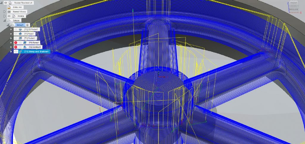
                                                    Well I think I may be getting somewhere now, Fusion suggests that the contour and ramp options which I was using are best suited to vertical or near vertical surfaces which probably explains why my horizontal ones were not ideal. I have found another option that they call "steep & shallow" which allows you to set stepover on horizontal surfaces and stepdown on vertical as well as "scallop" that Andrew mentioned.

                                                    Quickly entered in the same tool and 0.2mm values the results give a different tool path which sees the tool running along the length of the spokes much like Barrie said he would use and the simulator shows that leaving a much better finish, time is a bit longer but I could likely up the distance on the near vertical faces to compensate and would also gain a bit of time back with less Dremel work. I'll be trying this on the next suitable part. Pic of the revised toolpath.

                                                    steep n shallow.jpg

                                                    #465182
                                                    Andrew Johnston
                                                    Participant
                                                      @andrewjohnston13878
                                                      Posted by Ron Laden on 16/04/2020 08:40:12:

                                                      I learnt something to, didnt know that there are two part flywheels.

                                                      Quite common with larger flywheels, for a number of reasons:

                                                      The size of pattern and mould needed

                                                      The capacity of the foundry to melt and pour cast iron

                                                      Transportation of the flywheel to the customer. Moving something 30 feet long and 15 feet high is one thing. A 30 foot diameter part is a whole different ball game. Even with modern transport it'd be a challenge; there aren't many road bridges with a 30 foot high clearance!

                                                      Andrew

                                                    Viewing 25 posts - 176 through 200 (of 383 total)
                                                    • Please log in to reply to this topic. Registering is free and easy using the links on the menu at the top of this page.

                                                    Advert

                                                    Latest Replies

                                                    Viewing 25 topics - 1 through 25 (of 25 total)
                                                    Viewing 25 topics - 1 through 25 (of 25 total)

                                                    View full reply list.

                                                    Advert