Further Adventures with the Sieg KX3 & KX1

Advert

Further Adventures with the Sieg KX3 & KX1

Viewing 25 posts - 126 through 150 (of 383 total)
  • Author
    Posts
  • #430469
    Ian Johnson 1
    Participant
      @ianjohnson1

      CNC making a tricky little bracket easy peasy. And I'm getting to like the Fusion adaptive tool paths, I didn't understand how they worked at first. My Vectric Vcarve takes more normal cuts.

      Advert
      #430485
      JasonB
      Moderator
        @jasonb

        Yes the adaptive paths are quite good and should mean the table has to move about less particularly if cutting in both directions (thanks Andrew) . There are some odd moves it throws in that you think whey did it do it that way.

        I also need to look at tolerances for these cuts as when using the adaptive to rough out it likes to go back and take very fine cuts in some places like corners which is not really needed when roughing, I think it is trying to get all the material left to within the specified thickness which on the above was 0.5mm when anywhere between 0.4 and 0.6 would not be a problem and reduce run time..

        Edited By JasonB on 26/09/2019 08:04:01

        #430506
        Old School
        Participant
          @oldschool

          I have drawn up some wheel hubs, some of the hub is by adaptive tool paths but the the bearing housing is a conventional hole, I have set the tolerance for that at 0.01mm it's going to be interesting to see how the KX1 gets on. Cut a couple of spare blanks. They are going to be the front wheels of an old timer British tether car from 1954 an Ian Moore No 12.

          #430507
          JasonB
          Moderator
            @jasonb

            Let us know how it goes. Although you can set a tolerance there are things like backlash compensation and whether your cutter is on size as well as any run out on the spindle/holder/collet combination to take into account.

            May be worth doing a trial run or at least having the hole as a separate code and start a little under required size then you can adjust and run the code again without removing the work.

            #430519
            Andrew Johnston
            Participant
              @andrewjohnston13878

              As well as the issues mentioned by Jason there is also the matter of how good the software is at fitting a series of straight lines into a circular movement and how well the machine follows them. In my experience an interpolated hole can be anything from 0.02mm to 0.1mm out of round depensing upon size, material, and feedrate. I think Tormach did a video some years ago on hole accuracy and concluded that if you need an accurate, and round hole, use a boring head.

              Andrew

              #430520
              Andrew Johnston
              Participant
                @andrewjohnston13878
                Posted by JasonB on 26/09/2019 08:03:33:

                I also need to look at tolerances for these cuts as when using the adaptive to rough out it likes to go back and take very fine cuts in some places like corners which is not really needed when roughing, I think it is trying to get all the material left to within the specified thickness which on the above was 0.5mm when anywhere between 0.4 and 0.6 would not be a problem and reduce run time.

                For roughing I might leave 0.5-1mm of stock and use a tolerance of 0.2-0.5mm. Even so my CAM software sometimes seems to faff around in places with teeny cuts.

                Andrew

                #443188
                JasonB
                Moderator
                  @jasonb

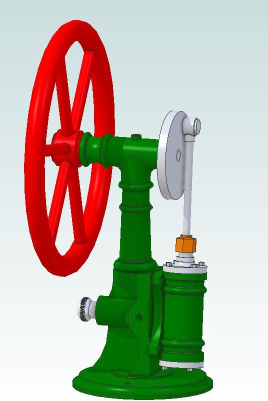
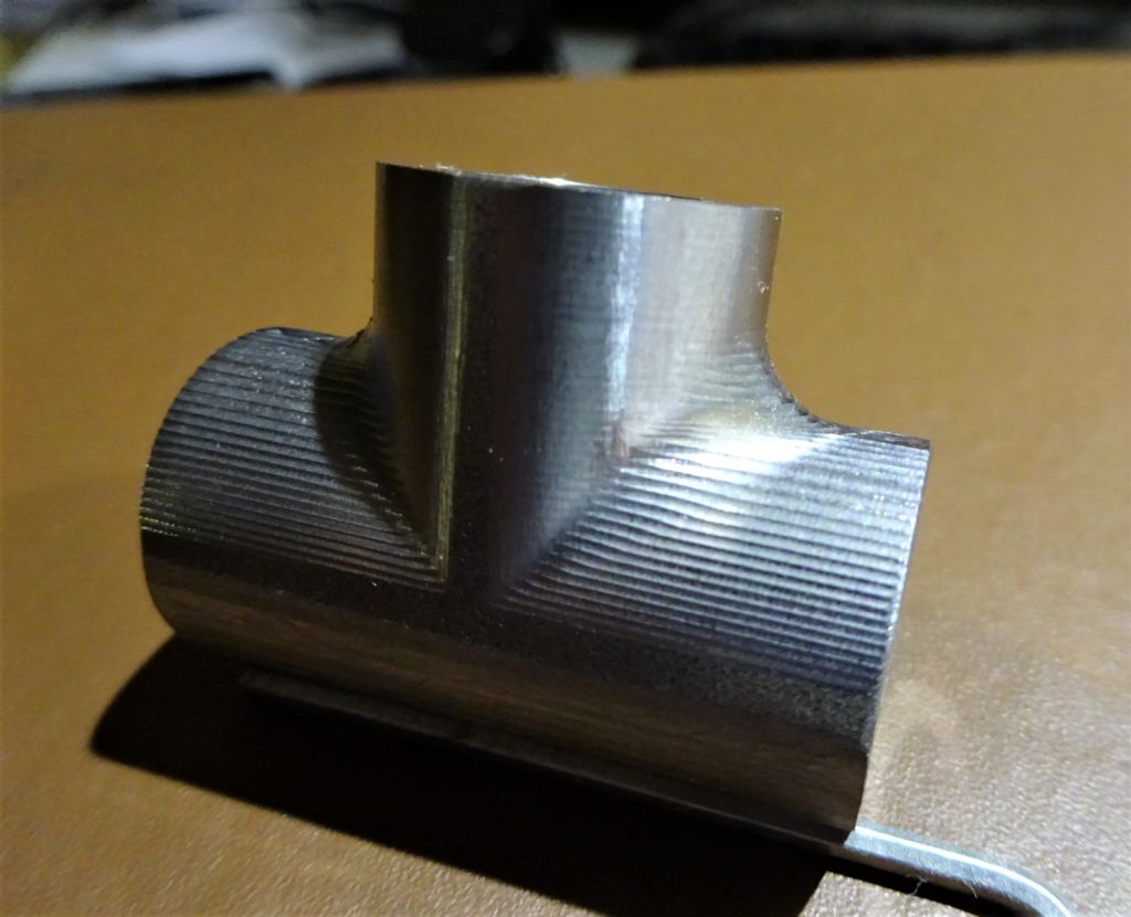
                  I wanted a "tee" shaped part similar to a plumbing tee where the 3 branches flow into each other rather than an abrupt junction for the top of the column of the engine I'm making at the moment.

                  3d.jpg

                  I could have done a simple cope joint and added the fillets with JBWeld or actually welded it and ground back the welds but thought as I have got the CNC that I may as well use it.

                  The bit of 40×20 flat steel bar was machined to overall size and the holes put in on the manual mill then over to the KX-3 to do the shaping. Just two paths, firstly a clearing one with a 3-flute carbide cutter then the final contour with a 4-flute 1mm corner radius cutter. quite pleased with how it turned out, just a tickle with files and or Dremel to blend in the cuts as I on;y went with 0.5mm stepdown.

                  dsc03888.jpg

                  #443256
                  Ron Laden
                  Participant
                    @ronladen17547

                    Nice work Jason, just a thought and I probably havnt thought this through enough but would using a ball nose cutter on the final cuts leave a smoother surface finish needing less hand finishing, with it been CNC I wonder if it would but maybe not.

                    #443264
                    JasonB
                    Moderator
                      @jasonb

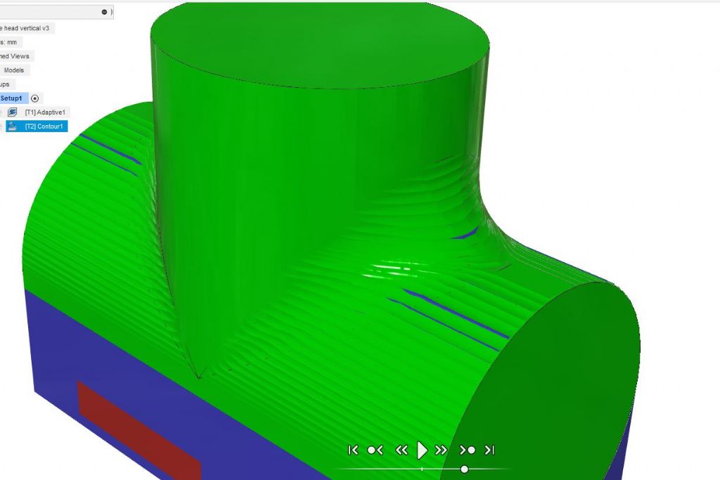
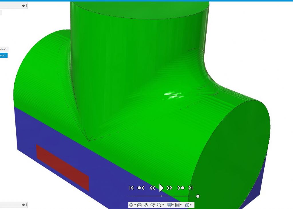
                      Hi Ron, Yes generally the larger the radius of teh cutter the smoother the finish will be but there are other things to consider.

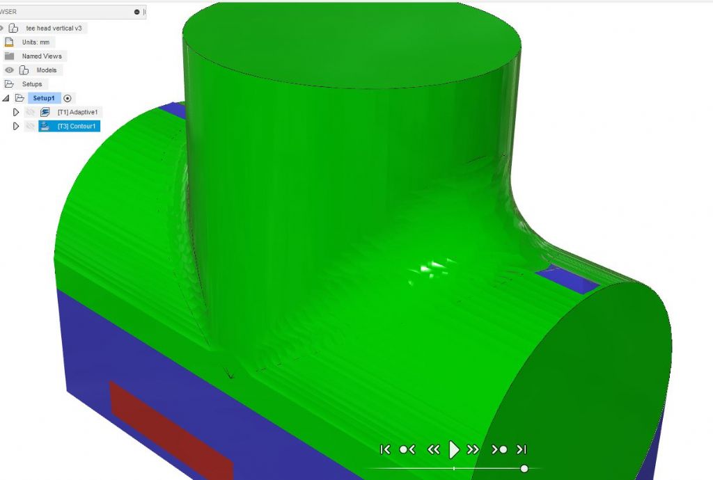
                      Firstly this shows the part enlarged in the CAM program as I cut it with the 6mm dia 1mm corner radius cutter, the couple of odd blue bits are in excess of 0.1mm of finished size, all the green is withing 0.1mm of finished size so not really that rough at least in my book and as I want to simulate a casting a bit of variance when hand finished will be a bonus.

                      r1 0.1.jpg

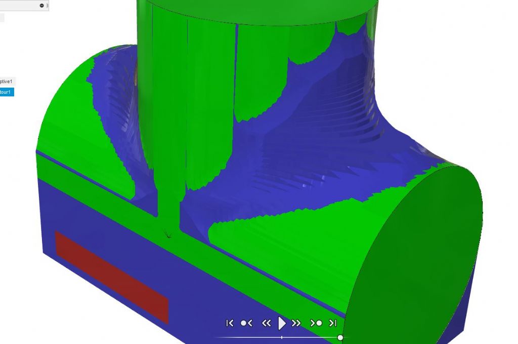
                      One simple way I could get it smoother is to reduce the step down between cuts, I did it at 0.5mm stepdown but this pic shows it done at 0.25mm stepdown, blue has gone and the green surfac elooks smoother but it would take twice as long to machine

                      r1 0.25 step.jpg

                      If I now run it with a 6mm ball nose cutter the green surface is even smoother but there are two isssues. Firstly on the more horizontal surfaces where the middle of the cutter is doing the work the cutting edges are not moving very fast so feeds may need to be slower and secondly as a lot of ball nose cutters are 2 flute then if the chip load is to be kept the same you would need to feed at half the speed so again twice as long to machine though I do have some 4-flute ball ended cutters that would be able to be fed as fast. Ignore the blue bit as I did not fully alter the CAM to suit the ball ended cutter but green is even smoother.

                      r1 01.jpg

                      Though you do have to be careful how large a radius you go for as it may not be small enough to get into the corners and to machine down as far as I have you would have more of the cutter below the widest point of the work so less to hold in the vice, this is with a 20mm ball nose which leaves a lot in the corners and the blue line along the edge is where I can't get to without hitting the vice

                      r10.jpg

                      So lots of factors to think about and that also depend on the cutters you have and how long the machine will be tied up which affects commercial users more than us hobby users

                      #443295
                      Ron Laden
                      Participant
                        @ronladen17547

                        Thanks Jason, quite a few factors there that I didnt consider.

                        #443524
                        JasonB
                        Moderator
                          @jasonb

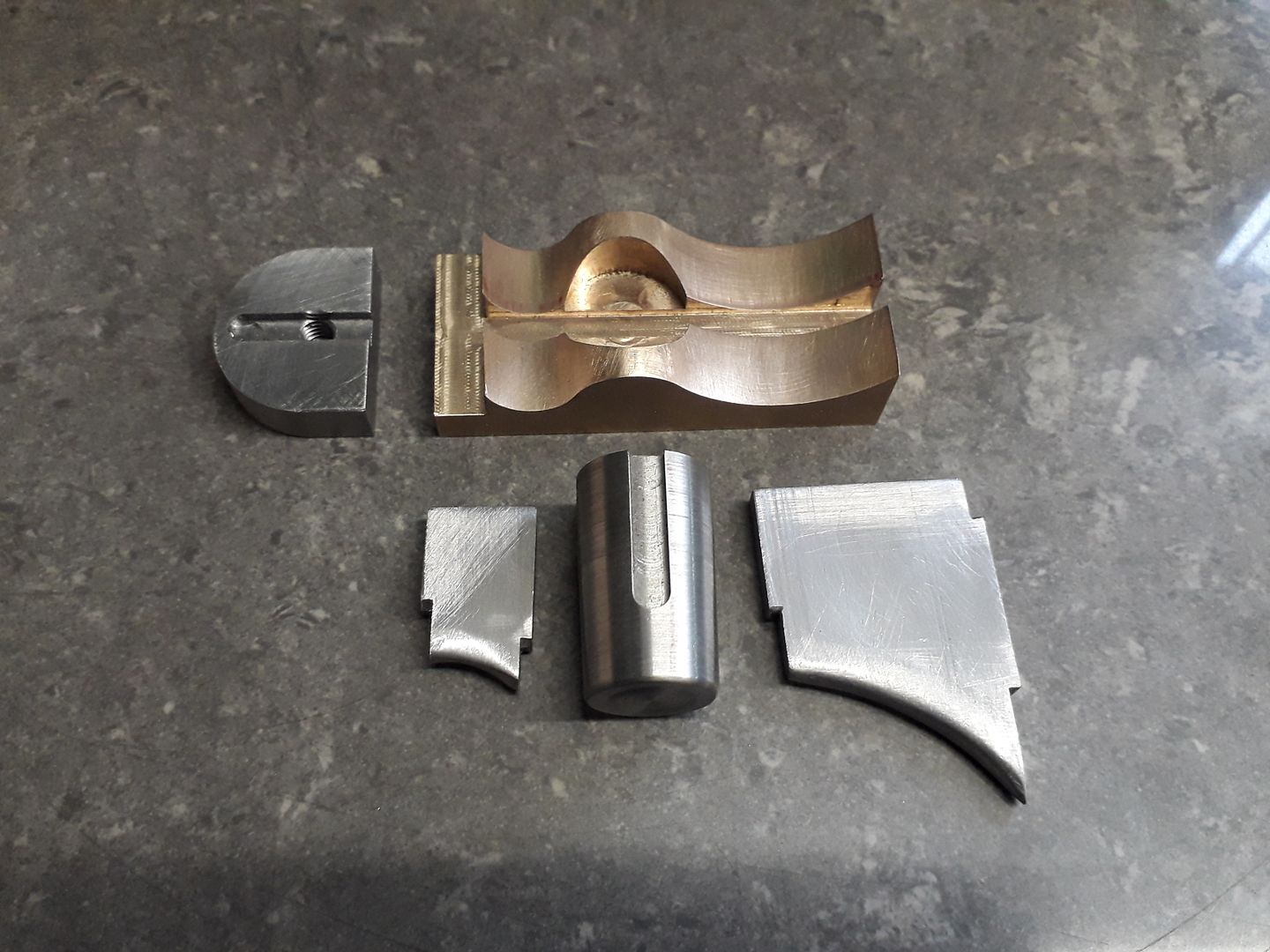
                          Another part for the same engine, this time the valve block at the base of the column cut from a block of bronze. Final contour done with a 6mm 4-flute ball nose cutter for Ron.

                          #443567
                          Ron Laden
                          Participant
                            @ronladen17547

                            That's quite some shape Jason, looks to have gone well. The ball nose seems to have finished off nicely, any issues in using it?

                            #443575
                            JasonB
                            Moderator
                              @jasonb

                              No it was cutting very well though you may be able to see that the CAM program stops it short of going right to the bottoms of the two "U" shapes so the very end was not being used.

                              It's all soldered up now and ready for final machining today.

                              #443581
                              Michael Gilligan
                              Participant
                                @michaelgilligan61133

                                Very impressive, Jason

                                The reflections of the tool in the surface of the workpiece, especially so surprise

                                MichaelG.

                                #443641
                                JasonB
                                Moderator
                                  @jasonb

                                  Thank's michael, I was happy how all three tools cut with very little sign of any burrs which are always an indication of a blunt tool particularly on bronze. The straight ones had done previous work but the ball ended one was new which also helped.

                                  Seems a pity to have to take a file to it and then discolour it by silver soldering but needs must and as it will get painted anyway I'm happy.

                                  Rest of teh bits to be soldered

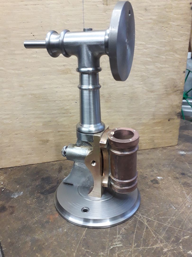
                                  And after final machining of the fabricated "casting" with the rest of the engine to date, you can also see the "tee" at the top that I showed a couple of days ago.

                                  Edited By JasonB on 28/12/2019 18:27:20

                                  #443702
                                  Ron Laden
                                  Participant
                                    @ronladen17547

                                    Nice work Jason, certainly looking like it all came from castings.

                                    #455421
                                    JasonB
                                    Moderator
                                      @jasonb

                                      I wanted an oval shaped base for a small model so decided to use a bit of Corian. I cut a rectangle a little over the desired 80mm x 60mm and drilled the holes for mounting the engine which were then used to hold the part onto a block of aluminium that could easily be held in a vice and allow the edge of the tool to be used without risk to the jaws.

                                      Profile is with a 10mm 4-flute carbide cutter running at 5000rpm and feed rate of 450mm/min, full 12mm height and 2mm per roughing pass with a 1mm to finish.

                                      The moulded edge wa sdone using a router but at a slow 5000rpm and the same 450mm/min feed, I would usually be running this at 20,000rpm plus in a router but it gave a good finish at that feed rate.

                                      Only downside is the confetti that is attracted to any surfaceangry

                                      #455449
                                      Ron Laden
                                      Participant
                                        @ronladen17547

                                        There are two things I like about it Jason, it's not wood and it's not round. Nothing wrong with a round wooden base of course but I think it good to see something a bit different now and then.

                                        You have mentioned Corian before I will have to see if I can find someone local and get some offcuts.

                                        #455452
                                        John Haine
                                        Participant
                                          @johnhaine32865

                                          Corian is lovely stuff to machine, even at low speeds – also fine with normal milling cutters. Local guy round here does Corian kitchen & bathroom surfaces, has a skip full of stuff too small for his uses but plenty big enough for many ME bits.

                                          #455453
                                          JasonB
                                          Moderator
                                            @jasonb

                                            Ron, I have shown it being used in several builds, couple more engine bases including one early in this thread, Basis for an old style knife switch and several times as an insulator for ignition parts. As John says it is nice to machine but can be a bit brittle and snap if you use it for the wrong part.

                                            You may also like this which is neither wood or round. wink 2

                                            #455455
                                            Joseph Noci 1
                                            Participant
                                              @josephnoci1

                                              Hopefully not to far of topic – does go on about Corian though…

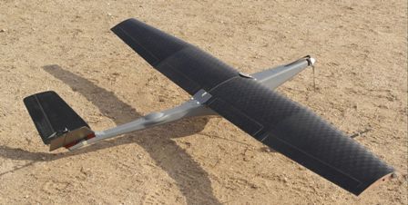
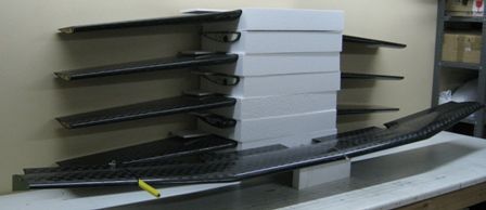
                                              I use Corian for moulds for the wings and fuselage of the small UAV below – Corian is fantastic for this. Holds a very fine edge very well in machining, and imparts that same fine edge to the composite in the mold. Corian also polishes up very well, and will leave a glossy finish on the molded product. Molds were made on a large CNC machine, for wings and fuselage. The Wing upper mold took 8 hours, the lower, 5 hours. Fuselage halves took 6 hours each. Wing has 3meter span.  The molds are rigid, no bend of flop to them, and very stable under temp – we bake the mold with internal composite parts at 90degC for 2 hours – the molds hold the shape very well. Really an amazing material. The molds for this plane are at the workshop and I find I have no photos of them! – I will get photos at some point if anyone is interested.

                                              Joe

                                              SurVoyeur MK11.jpg


                                              obl_rear_2005.jpg


                                              wing.jpg

                                              wing sets 2.jpg


                                              Edited By Joseph Noci 1 on 05/03/2020 07:14:23

                                              #455526
                                              Ron Laden
                                              Participant
                                                @ronladen17547

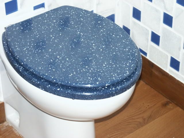
                                                Will have to get some, I can think of a few uses for it but no I wont be making a toilet seat though it does look good.

                                                I think I remember a curved lid which you made for a box, that was impressive also.

                                                Ron

                                                #463305
                                                JasonB
                                                Moderator
                                                  @jasonb

                                                  The current lockdown has allowed me to spend a bit more time on the darkside

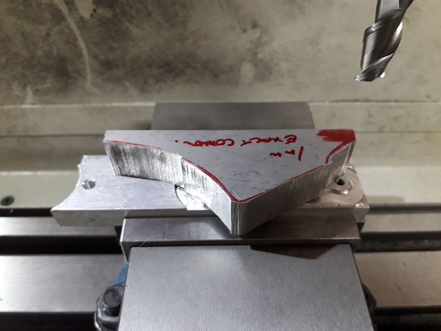
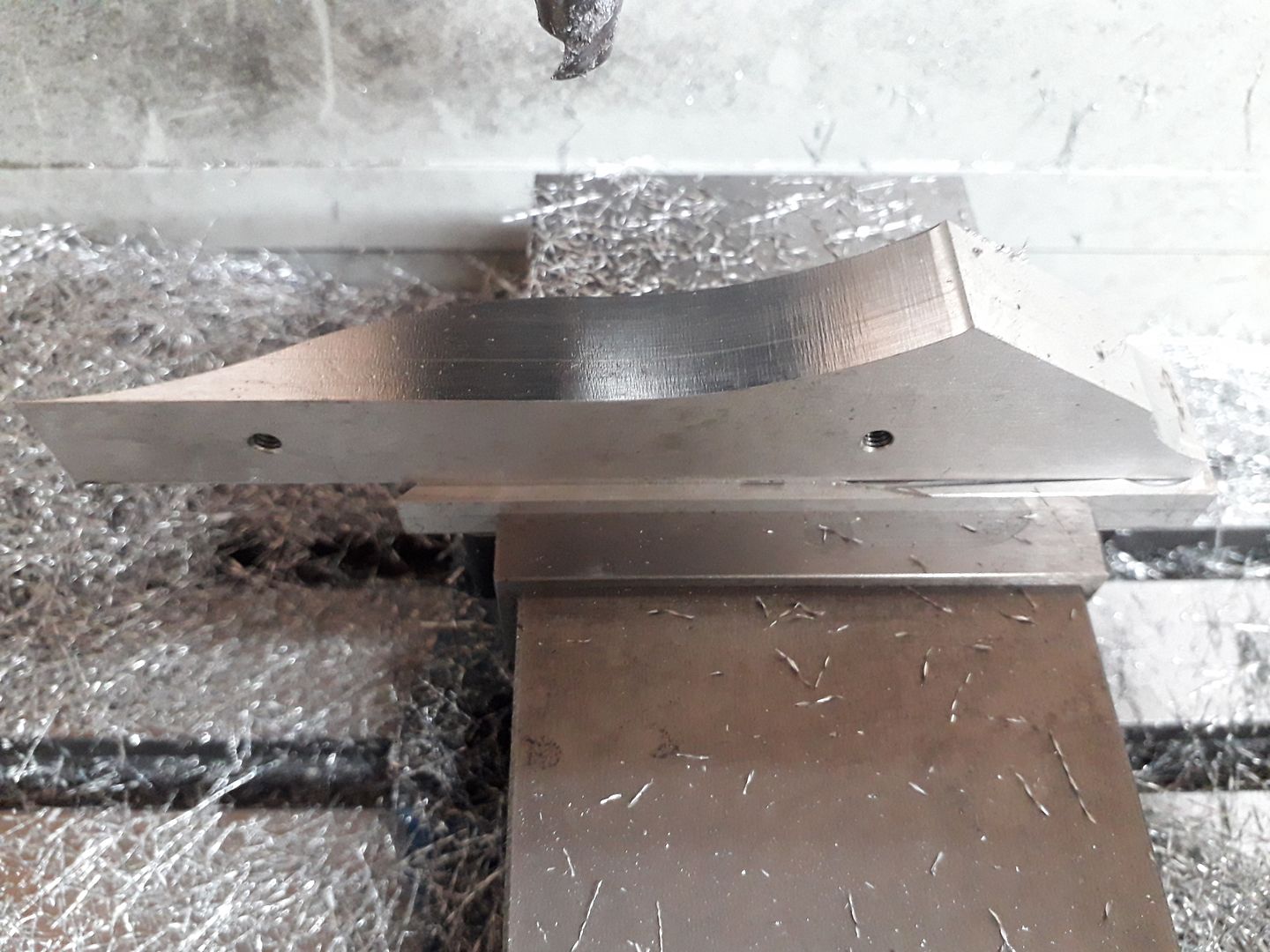
                                                  I was not going to bother videoing this but with the other thread about profile cuts thought I would. I did two tool paths in F360, one a roughing contour leaving 2.5mm stock all round and then the final contour taken at the full 16mm depth of the material in 0.5mm depths with a 0.25mm finish past & a spring pass which was not really needed. However I actually did the roughing on the vertical bandsaw to a Sharpie line drawn around a paper template so only needed to run the second path.

                                                  This shows the smaller of the two parts which is tapped and screwed to some scrap being held in the vice so the tool can extend just below the bottom of the work.

                                                  This is the larger part being milled with one of ARC's 10mm dia aluminium specific cutters running at 4000rpm and feed at 300mm/min. Quite pleased with the finish from what is a quiet well used cutter as you can see from my finger reflection if you skip to the end.

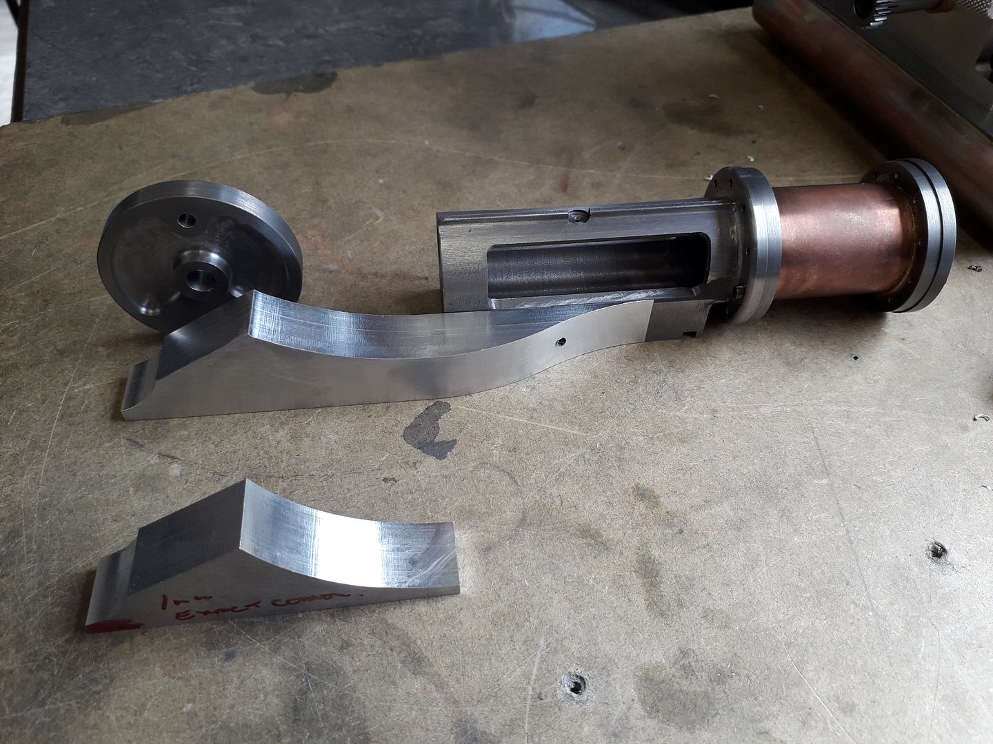
                                                  It was then mounted the right way up to mill the "S" shape on what will be the side.

                                                  Can you tell what it is yet?

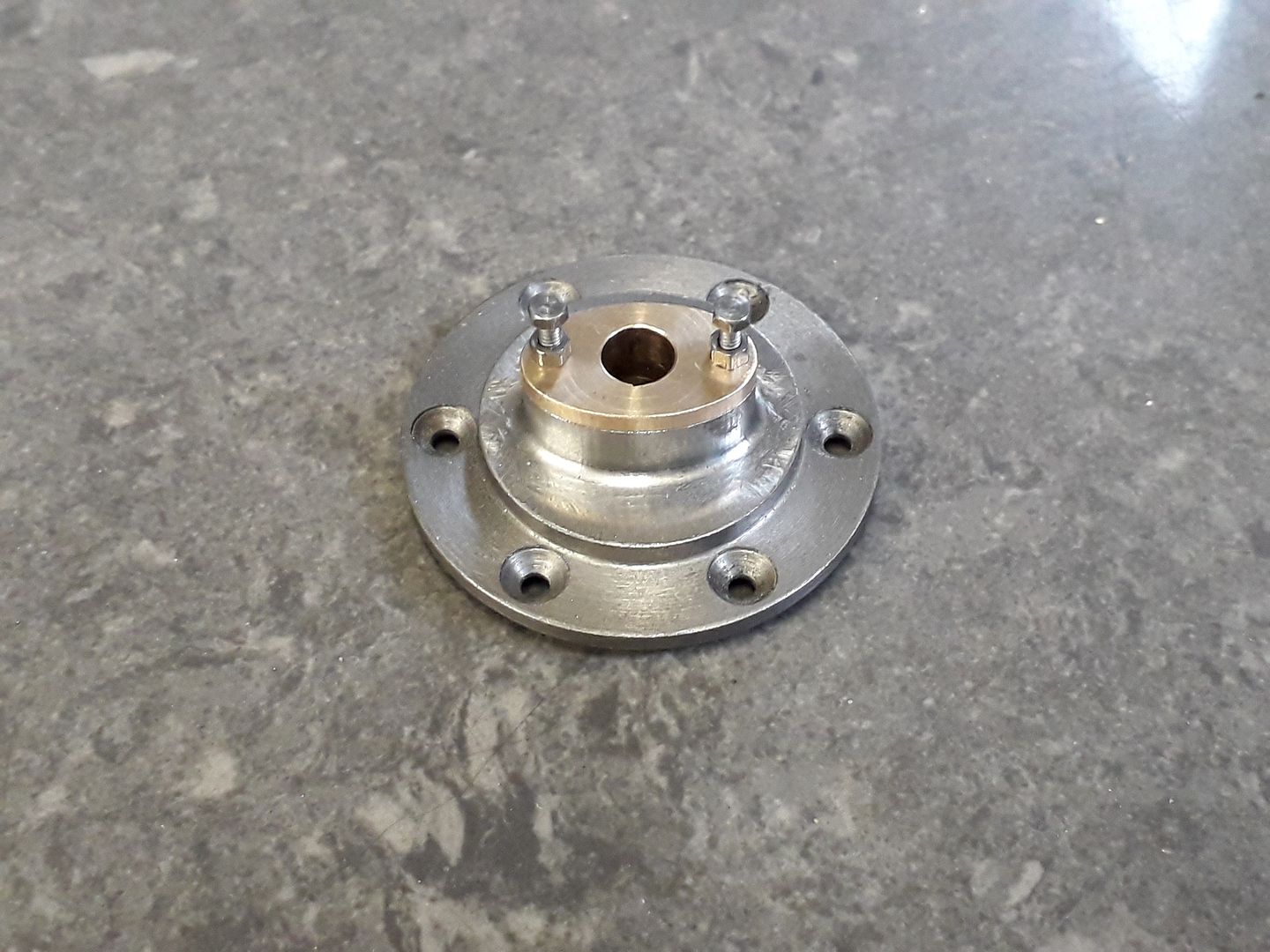
                                                  The crank disc in the photo above had the recesses either side done on the CNC as did the cylinder end cover and its boss which were both shaped at the same time.

                                                  J

                                                  #463427
                                                  Ron Laden
                                                  Participant
                                                    @ronladen17547

                                                    Nice work Jason, great finish on the aluminium. I have no idea what it is except there are some interesting shapes there especially the piece next to the cylinder

                                                    #463441
                                                    Baz
                                                    Participant
                                                      @baz89810

                                                      I know what it is! It’s Jason’s next build thread complete with drawings👍😄

                                                    Viewing 25 posts - 126 through 150 (of 383 total)
                                                    • Please log in to reply to this topic. Registering is free and easy using the links on the menu at the top of this page.

                                                    Advert

                                                    Latest Replies

                                                    Viewing 25 topics - 1 through 25 (of 25 total)
                                                    Viewing 25 topics - 1 through 25 (of 25 total)

                                                    View full reply list.

                                                    Advert