Further Adventures with the Sieg KX3 & KX1

Advert

Further Adventures with the Sieg KX3 & KX1

Viewing 25 posts - 51 through 75 (of 383 total)
  • Author
    Posts
  • #405910
    Ron Laden
    Participant
      @ronladen17547

      Jason, I dont want to detract from this thread but a couple of questions if I may. Does the Corian take paint ok and the adhesive type to be used with it.

      Ron

      Advert
      #405918
      JasonB
      Moderator
        @jasonb

        yes it paints OK, the bed plate of this engine has held it's paint Ok for a number of years.

        They make a specific colour matched epoxy adhesive for it but I have used superglue, JB Weld and various epoxys to stick it with and all seem to hold OK.


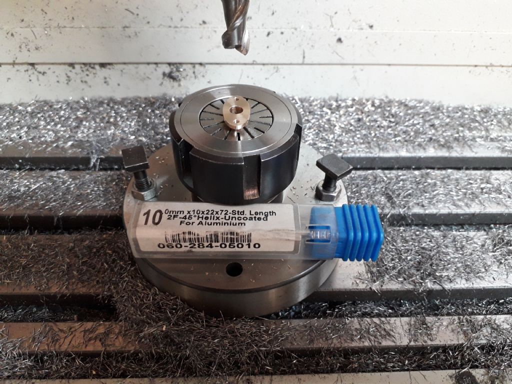
        Just something simple of the KX-3 today in the form of a truely elliptical gland flange and a couple of 2mm holes. I used one of ARC's aluminium specific cutters as the uncoated carbide works well in other non ferrous materials too. Had to be sure my heights were right as there was not a lot of clearance between the collet and the underside of the flange particularly when the drill broke through.

        20190421_143314.jpg

        Edited By JasonB on 21/04/2019 17:09:37

        #406329
        JasonB
        Moderator
          @jasonb

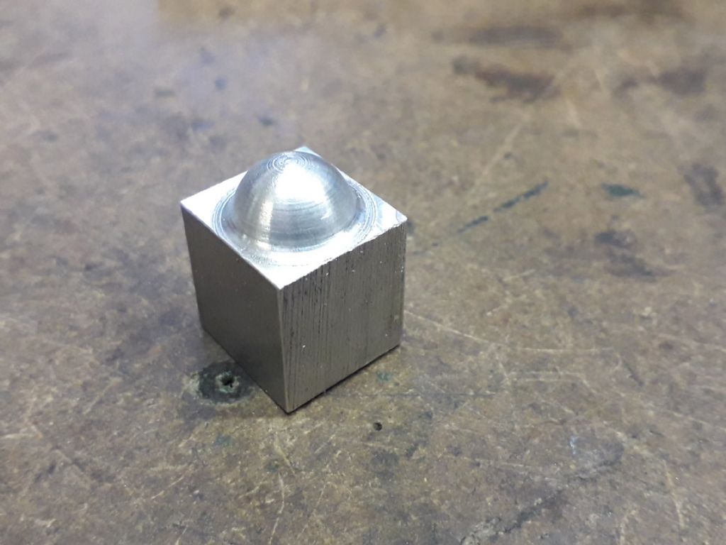
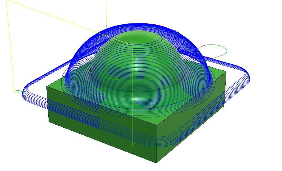
          Had a go a 3D machining this evening, just a simple dome but quite pleased with it for a first attempt. Did adaptive clearing to get rid of most of the waste, then finish machined the 4 flat areas at the top of the square with a 6mm 3-flute cutter before changing to a 1/8" HSS ball nose to refine the dome.

          Ball nose was a bit past its best so possibly explains the poor cuts towards the top and I did not spend long enough setting tool heights right so a bit overcut where the dome fillets out to the flat.

          20190424_193028.jpg

          #406334
          Andrew Johnston
          Participant
            @andrewjohnston13878

            Looking good! thumbs up

            The poor finish on the top is more likely to be due to slow cutting speed. I assume that the hemisphere was finished using a series of concentric paths, each one moving out and down slightly. At the top the cutter is only working on the centre, so the cutting speed is small (zero at the centre of the cutter). For a given feedrate the chip load is then large and the tool may be more rubbing than cutting. As one moves out and down the cutter starts cutting more on the side so the cutting speed goes up and the chip load goes down, giving a better finish.

            Depending upon the part geometry the issue can be overcome by tilting the part, or using a 5-axis CNC mill that adaptively tilts the tool so it's always cutting on the outer part of the ball. smile

            Andrew

            #406342
            Former Member
            Participant
              @formermember32069

              [This posting has been removed]

              #406357
              JasonB
              Moderator
                @jasonb

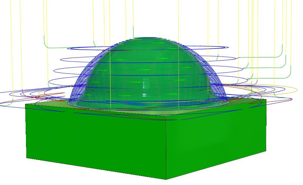
                Thank's Andrew, you assumed correctly that the contour was a series of circular cuts and as you say the middle of the cutter will not be doing much at the top pf the dime. I remember Murray's post about tilting the work which worked well, not having even 4th let alone 5th axis the other option that may be more affordable would be to invest in a radius corner cutter or "Bull Nose" as the Americans call them which would get the speed at the cutting edge up. I may simulate that as F360 has those cutters already in the tool library. Only downside I can see in using them is you can't get into tight internal corners in the X-Y plane.

                dome contour.jpg

                Barry, there are several options that I still need to get my head around depending on the orientation of the curves on the part where the path can be set to give a more suitable step over. I need to watch the video again and do a few more trials to see what works best.

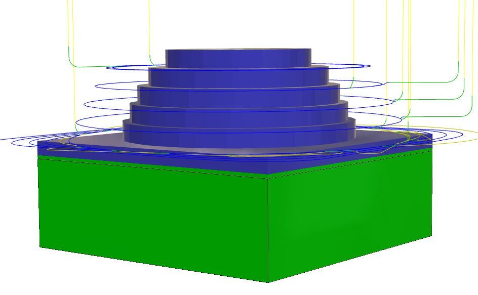
                For the clearing I used 0.5mm cuts and 1mm vertical steps, the final contour to the dome was done with 0.1mm steps. Purple is waste still to come off, set to leave 0.5mm which I assume its at teh thinnest points and that would be about 1.3 at its thickest.

                dome adaptive.jpg

                #406360
                Former Member
                Participant
                  @formermember32069

                  [This posting has been removed]

                  #406361
                  JasonB
                  Moderator
                    @jasonb

                    Thanks again Barrie, I do seem to remember from the videos that you can pick certain areas of the contour and specify different speeds, cutting directions etc which is something I will have to study more. I also need to find where to change stepdown to step over. Will also look to reduce the roughing steps.

                    I just changed the tool to a 6.0mm dia 1.0mm corner radius one and ran the simulation. At my max speed of 5000rpm it gives a surface speed of 95m/min which is the full 6mm dia so allowing for the 1mm radius the cutting speed when the very bottom of the tool is being used at the top of the dome would be around 63m/min at 4mm diameter which is quite an improvement on the near zero speed of the 3mm round nose tool. I also has the bonus of being able to finish the flat areas in the corners and would not be too bad to do the initial roughing as well so no need to change tooling.

                    Blue line shows path of ctr of the tool which is now further from the finished surface so actual cutting speed is up.

                    dome bull nose.jpg

                    #407272
                    David Taylor
                    Participant
                      @davidtaylor63402

                      One thing I've learned the hard way is to look at the movements of the tool during the sim and in the toolpath. Some yellow lines (Fusion360 specific) can be easy to miss and a tool might go tearing straight through a stud or clamp in the middle of the stock when you didn't think it would because it was just cutting around the outside.

                      I usually make the clearance heights a bit low to save on head movements, but obviously it's called clearance for a reason! Plus of course you can model your studs and fixtures etc.

                      As for writing g-code I was also put off by all the articles that went though manually coding parts, not to mention the cost. But in 8 months I've not written a line of g-code, and only altered them a few times.

                      #417337
                      JasonB
                      Moderator
                        @jasonb

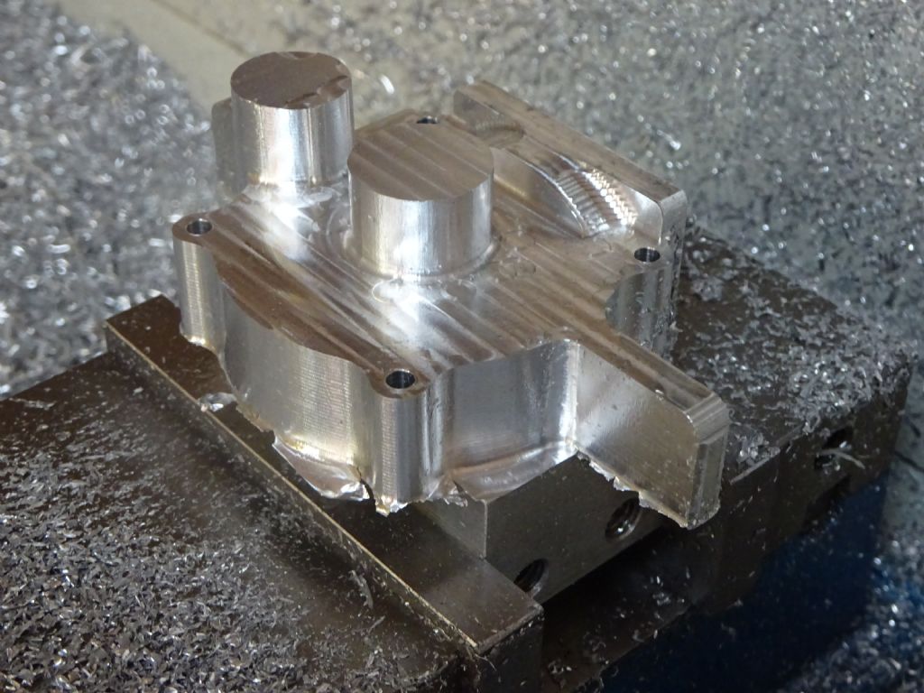
                        I've not had the need to do much on the KX3 over the last couple of months but thought I had better blow the dust off it and see if it (and me) could handle something a bit more complicated. I have been drawing up a 24mm bore single cylinder 4 stroke with side rods loosly based on a design published in Practical Mechanics in 1938 with the intention of CNC machining the two crankcase halves.

                        So with a piece of 1" 6082 T6 aluminium mounted onto a holding block I loaded up the code and let rip.

                        The first 3 clips in the video show the 3D adaptive clearing which was done using one of ARC's 6mm 2-flute aluminium specific HSS cutters, I was in two minds whether to use this as I had noticed a bit of chatter when using it in the manual mill in the past particularly as I wanted 27mm sticking out of the collet so that would not crash into the work but after a chat with Ketan a while back I decided to give it a go. 5000rpm, 8.5mm height of cut (1/3rd stock height) 1mm depth of cut, feed rate of 300mm per min giving achip load of 0.03mm which was just right and did not need altering. 0.5mm material left for finishing

                        4th clip is the same as above except height is reduced as the surface was between the two 8.5mm increments, this is where a tiny amount of chatter could be heard on the lighter loaded cutter.

                        Clips 5-7 are the 3D contour which was used as the sides of the crankcase all have draft angle rather than vertical sides. I used a 2-flute carbide 6mm cutter with 1.0mm corner radius. Again run at 5000rpm, with a 0.5mm stepdown and the DOC was the 0.5mm that was left, feed 400mm/min. In hindsight a 4 flute cutter would have been better as the amount of swarf was not great so the 2-flutes extra clearing capacity was not needed and then I could have fed faster.

                        Clip 8 Spotting the bolt holes with a 5mm HSS spotting drill at 5000rpm

                        Lastly drilling the 3mm holes with a Dormer A002 split point drill at 5000rpm and using a pecking cycle to clear the swarf.

                        dsc03700.jpg
                        The bit of flash around the bottom is due to me doing the CAM for 25mm stock but using 1" , there are a couple of things I will alter slightly for the other half but overall I'm quite pleased with how it turned out. particularly the tapered surfaces as I was expecting them to need more fettling but they are quite smooth and will just need a quick rub with emery before blasting the surface to get it to look like a casting.
                        #417340
                        Ron Laden
                        Participant
                          @ronladen17547

                          Well that saved some work Jason, looks good. How long did the programme take, is it a quick process, I can appreciate the more complex the longer the programming.

                          Ron


                          Edited By Ron Laden on 04/07/2019 19:37:16

                          #417346
                          JasonB
                          Moderator
                            @jasonb

                            About 1hr 41mins machine time plus the changing of tools. Seems a long time but still a lot faster than doing it on the manual mill. removed 44% of the original block though there is still more to be turned to swarf when the other side is hollowed out. Alibre says the block started out at 307g and the finished part will eventually weight 63g.

                            Just over 100,000 lines of G-code, thank God the CAM writes that for me.

                            Edited By JasonB on 04/07/2019 20:22:22

                            #417352
                            Neil Wyatt
                            Moderator
                              @neilwyatt

                              Excellent work Jason.

                              Sadly can't see myself getting up and running before September now

                              #417354
                              Andrew Johnston
                              Participant
                                @andrewjohnston13878

                                Looks good!

                                As always I might have done a few things differently, but who's to say I'm right or wrong. smile

                                I'm either going to have to upgrade my CAM program or start using Fusion360 so I can get going with adaptive toolpaths.

                                Andrew

                                #417381
                                JasonB
                                Moderator
                                  @jasonb

                                  Thanks for the interest chaps,

                                  Andrew I'm always interested in how the more experienced user would have gone about things. There are a couple of things that I will do differently when I do the other half such as see if I can do a finer stepdown on the curved portion under the head flange and also make sure I put the correct stock size in as the last minute change to slightly thicker and +1 mm all round left a few bits that should have been removed, the simulator did show this but I did not spot itblush

                                  If anyone is going to the Guildford Gala Weekend then I will be there tomorrow only and you can see this part in the flesh plus a few of my recent engines.

                                  #417400
                                  Ron Laden
                                  Participant
                                    @ronladen17547

                                    Jason, I see you used some cutting fluid for the drilling, fluid or coolant is obviously not required for the milling..?

                                    Its the 5000 rpm that always makes me wonder but I guess cutting aluminium with a 2 flute carbide Alu cutter there is no real benefit, it obviously works well enough dry.

                                    Ron

                                    #417407
                                    JasonB
                                    Moderator
                                      @jasonb

                                      It's what you can't see that matters. I have not got anything set up yet to clear the chips and/or lubricate.

                                      I am giving the occasional blast with the air gun to clear swarf and brushing on a little paraffin every so often . What I also found works quite well is to hold the brush just in front of the air gun and that clears the swarf and sprays the lubricant at the same time with reasonable size droplets so you don't get a mist. It is just that I can't do both of those and hold the camera at the same time.

                                      Looking at the cutting data from another maker of similar high helix uncoated 2-flute cutters designed for aluminium and non ferrous they give a speed of 7000rpm for a 6mm in aluminium so my 5000rpm max is as near as I can get. The same chart also gives data for a similar type of cut as 1xD high and 0.25 x D deep which equates to 6mm x 1.5mm which is a similar amount of metal removal to my 8.5 x 1. However where I did go quite a bit easier was with the feed rates due to the fact I was using a long series cutter and only have manual swarf clearance and lube so rather than feeding at 900mm/min suggested I went with 300mm/min.

                                      #418831
                                      JasonB
                                      Moderator
                                        @jasonb

                                        And then there were two

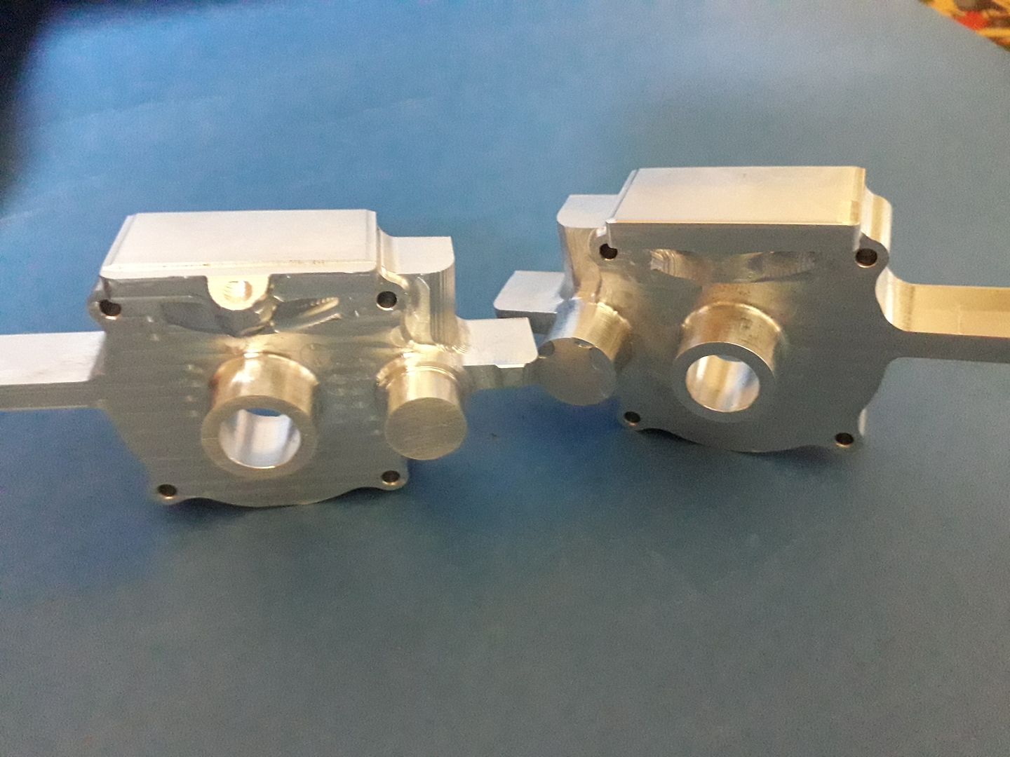
                                        Much the same setup as the other half with the addition of a contour cut to form the reduced diameter spigot on the cam shaft boss that will take the ignition contact so timing can be advanced/retarded. I also remembered that I bought a 4-flute radius corner cutter at the same time as the 2-flute and as it was not taking much off per pass there was no need to worry about swarf clearance so I used that and upped the feed to 500mm/min which cut the time a bit.

                                        #418936
                                        Ron Laden
                                        Participant
                                          @ronladen17547

                                          Looking good Jason, I bet that saved some time over doing them manual.

                                          #418942
                                          JasonB
                                          Moderator
                                            @jasonb

                                            Yes, having done a couple the manual way it is certainly quicker, whether it is a satisfying is debatable and certainly not so high on the willy waving scale.

                                            #418952
                                            Old School
                                            Participant
                                              @oldschool

                                              I am impressed with what you are managing to do with your machine. Must stop using the manual mill and get on with the using the KX1 got some Fusion 360 drawing done just need to get the g code done and cut metal.

                                              #419170
                                              Andrew Johnston
                                              Participant
                                                @andrewjohnston13878
                                                Posted by JasonB on 15/07/2019 07:39:17:

                                                Yes, having done a couple the manual way it is certainly quicker, whether it is a satisfying is debatable and certainly not so high on the willy waving scale.

                                                I'd argue that it's more satisfying and higher up on the willy waving scale. After all in order to produce the part one needs to create the design and be able to use 3D CAD. Then one needs to create the G-code and cutting schemes which requires a proper understanding of speeds and feeds versus depth and width of cut. Fixtures also need to be created that allow the part to be machined without getting in the way of the cutter or chuck.

                                                Andrew

                                                #419179
                                                JasonB
                                                Moderator
                                                  @jasonb

                                                  I suppose it depends on how you look at it,

                                                  For the manually machined engine crank cases I designed the parts and drew them up in 3D CAD so no difference there. Both design stages will take into account what you have available to make the part with and how you will use those items.

                                                  Granted you don't need to produce the G-code but you still need to plan a scheme or machining sequence for the type and order of the manual cuts. Also agree that to get the best out of the CNC machine you need to get feeds, speeds and type of cutting right especially as it is harder to alter things once you pres GO!

                                                  Fixtures were still needed to hold the parts as well as many setups on the lathe and mill so they could be manually machined. As for clashing I mentioned above that the tool needed to protrude a certain distance to prevent the collet hitting the work, this would be no different on the manual mill or making sure a boring bar is long enough on the lathe so you don't run the toolpost into the work though the manual methods may not result in such a big bang as it would if you got it wrong on the CNC

                                                  As for the waving scale there are a lot who would say doing something manually is a lot higher up the shaft than with CNC but may well have never actually tried it.

                                                  #419183
                                                  Baz
                                                  Participant
                                                    @baz89810

                                                    I have manual machines and also CNC mills and lathe, I don’t think it really matters how you make a part, the important thing is that you are making something.

                                                    #419188
                                                    John Haine
                                                    Participant
                                                      @johnhaine32865

                                                      There are things you can easily do with a CNC mill that are next to impossible manually. For example, for my current Synchronome-based clock project I have cut a pallet to a mathematically defined profile that gives a "raised cosine" impulse force waveform; and an equi-angular spiral cam. For both the coordinates were calculated and the g code generated in Excel.

                                                    Viewing 25 posts - 51 through 75 (of 383 total)
                                                    • Please log in to reply to this topic. Registering is free and easy using the links on the menu at the top of this page.

                                                    Advert

                                                    Latest Replies

                                                    Viewing 25 topics - 1 through 25 (of 25 total)
                                                    Viewing 25 topics - 1 through 25 (of 25 total)

                                                    View full reply list.

                                                    Advert