Further Adventures with the Sieg KX3 & KX1

Advert

Further Adventures with the Sieg KX3 & KX1

Viewing 25 posts - 301 through 325 (of 383 total)
  • Author
    Posts
  • #582868
    Adam Stevenson
    Participant
      @adamstevenson91624

      The amount is set for the drivers so please don't try to get more for them as it will likely damage the driver or motors. First thing to check is that the force you are applying to turn the screw is constant. Use a torque ratch to check the jigs are not binding. Also check all screws are nipped but not too tight. Jason has posted a KX3 layout so here is a KX1 with longshine drivers.

      No image because I can't upload it but it is a real picture from a real KX1 that we ran at Arcuro trade shows.

      Edited By Adam Stevenson on 28/01/2022 23:15:59

      Advert
      #582871
      John Haine
      Participant
        @johnhaine32865

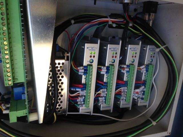
        OK the drivers are different so preferably need photos of Mick's machine control box. The Yako drives have a rotary switch to set current.

        I don't agree that there is much risk of damaging the motors or drivers by increasing the current a bit. Within the setting range of the drives the current is limited to the set value, and unless the motors are already running hot they are not going to overheat from a few minutes at a higher current. I've run the steppers on my mill for quite long periods nearly too hot to touch without issue, though I did establish that the high current wasn't needed so reduced it.

        But it's obviously a good idea to make sure everything is moving sweetly and not binding. From all the symptoms Mick described I still think it's most likely to be an electrical problem.

        #582873
        JasonB
        Moderator
          @jasonb

          As was suggested somewhere I would consider swapping the X & Y steppers over which should show up if it is the stepper that is at fault assuming they are the same.

          Does your manual not give the torque for the steppers? Mine gives X&Y as 4Nm and Z as 6Nm for the KX3

          #582877
          John Haine
          Participant
            @johnhaine32865

            Yes good idea. Swap the wiring initially so the Y drive runs the X motor and vice versa.

            #582889
            Emgee
            Participant
              @emgee

              If a stepper has gone faulty by losing or shorting a winding it could have caused damage to the driver, changing X & Y axis cables over could lead to the faulty stepper causing the same damage to the good driver, it's a risk you may not want to take.

              Best to check for equal resistance of the stepper coils and insulation resistance to the motor frame before changing leads over.

              Emgee

              #583053
              mick
              Participant
                @mick65121

                Good morning all. Haven't posted for a couple of days as we've had visitors! Update. I've tried swapping over the X & Y steppers, as the Y stepper wiring is part of a loom I could only swap the X (which maybe the problem) and connect to the Y stepper, there's no movement at all not even a slight stutter, swap them back over and all's fine. I've been through every page of my manual and there's no reference to any stepper motor torque. As I've said before I can only adjust the gib with the table centrally positioned and then I can only find one sweet spot that allows 50mm or so jog in both directions until the slide jams. I can move the slide to both limits by spinning a small BA spanner attached to the square on the ball screw using only one finger, so it would seem like the X stepper only needs a bit more umph to drive the slide to its limits. With 2,800 hours on the clock the limited movement may be due to wear as most machining is done with the table centrally positioned, but until I removed the gib and cleaned the slides the table could be jogged to limits, it was only the situation of programs stalling and the control loosing its zero home position that prompted me to clean the gib and slideways. As I've said, when it comes to electronics I'm a bit at sea, so would the consensus be that I try a new stepper motor and as there are no markings on the X stepper what torque would be the one to go for. Thanks.

                #583079
                JasonB
                Moderator
                  @jasonb

                  Sounds like your assumed lack of Torque is just a result of things going back together a bit tighter if the stepper was capable of jogging all the way before.

                  I'd leave the stepper alone and try to sort out the initial stalling that you mentioned, Don't think you detailed that in the last post when you were asked for an explanation of what the stall actually was.

                  Torque should be on the machine spec in the last section of the manual just before the parts diagrams etc.

                  20220130_130014[1].jpg

                  #583084
                  Ketan Swali
                  Participant
                    @ketanswali79440

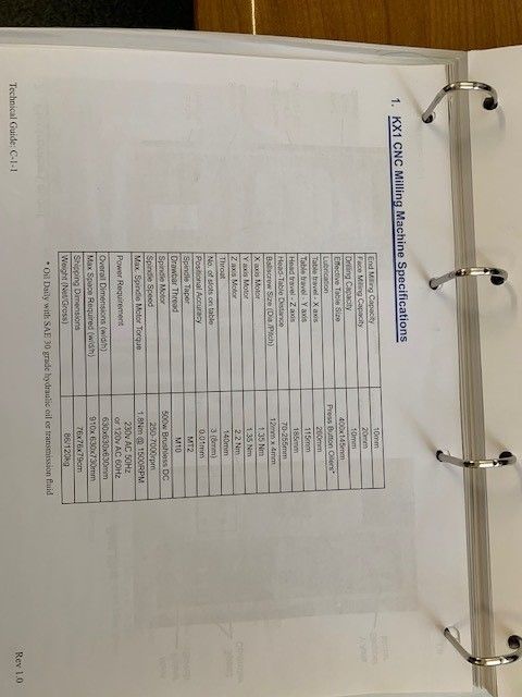
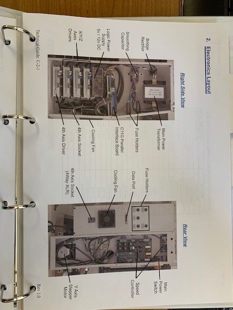
                    From the KX1 Manual put together by John Stevenson, Adam Stevenson and Alan Simmonds in 2008:

                    X & Y axis 1.35 Nm each, Z axis 2.2 Nm

                    technical guide page c-1-1.jpg

                    technical guide c-2-1.jpg

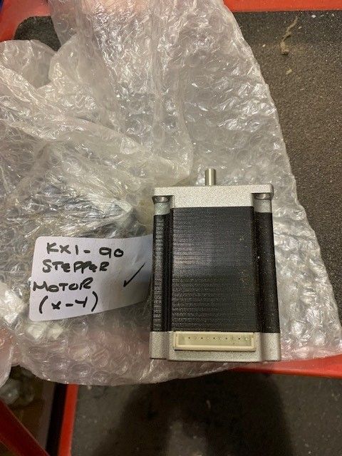
                    x and y axis steppers 1.jpg

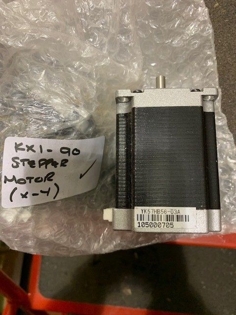
                    x & y axis steppers 2.jpg

                    • the KX1 machine which Adam Stevenson currently has, has different drivers, breakout and control board from the ones used in 2008/2009.
                    • The user may need to look at all the electrical connections to confirm non have become loose over time, or become loose due to some adverse event.
                    • Check the connections and operations of the micro switches,
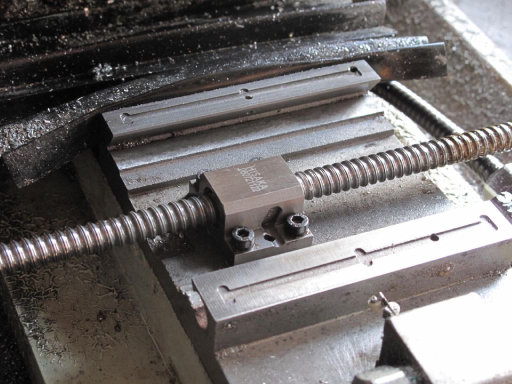
                    • check if the ball screw has not got contaminated, but to remove the screw and nut from the screw a specific procedure needs to be followed to avoid balls falling out of the nut- see You Tube videos (50% good/50% crap). Just winding by hand from the end does not prove that the ball screw is okay. contamination/swarf can move randomly, an observation which has been made in the past.
                    • the existing stepper motors as they stand (if they have not developed a fault) have enough torque to run the axis in question. To check if it is faulty/cause of the bind, one needs to disconnect it from the axis ball screw which is effected. (As I did not get involved in this dismantling process, I cannot guide.). Once disconnected from the ball screw, run it to see if it is okay. The stepper motor should/will be connected to the ball screw with an oldham coupling and/or similar. Most KXs made for supply through ARC at the time had be requested with such couplings.

                    I am unable to assist or advise on dismantling, re-assembling, electronics, computers or software.

                    Some electrical components are still available, without guarantee or warranty.

                    Ketan at ARC


                    Edited By Ketan Swali on 30/01/2022 13:32:59

                    Edited By Ketan Swali on 30/01/2022 13:36:31

                    #583139
                    mick
                    Participant
                      @mick65121

                      Thanks Ketan. Plenty to think about there, I'll start by disconnecting the stepper from the ball screw. The one thing that stopped me from completely removing the X axis slide for checking and cleaning was the prospect of loosing all the balls! Judging by the machine serial number mine is a 2009 machine. As I said its got over 2,800 hours on the clock and I'm completely lost without it as its become an integral part of my workshop. Thanks. Mick.

                      Edited By mick on 30/01/2022 17:05:14

                      #583171
                      John Haine
                      Participant
                        @johnhaine32865

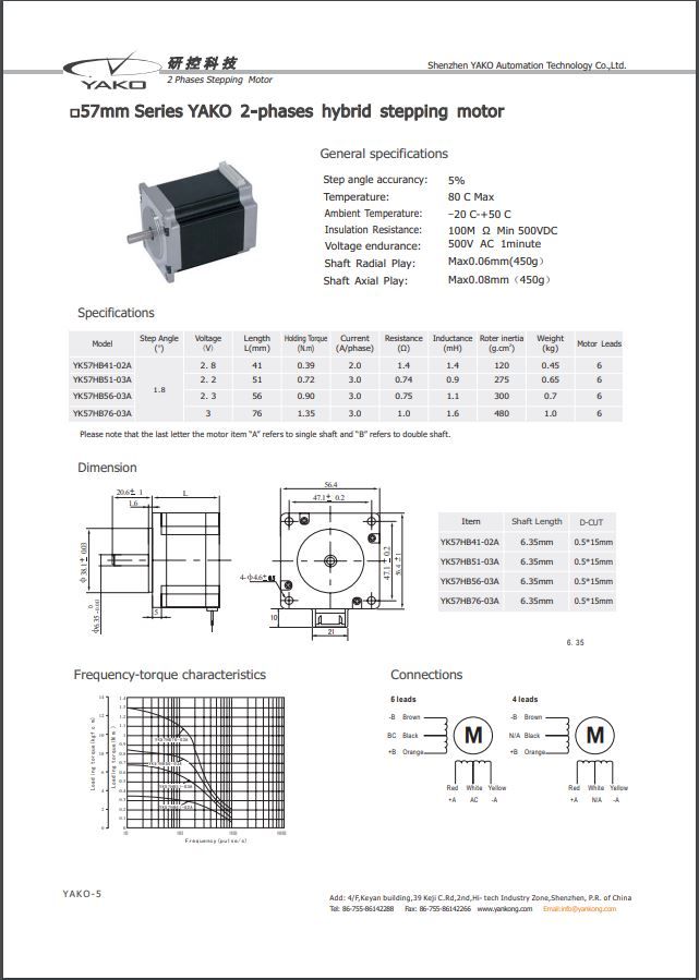
                        Here is a summary datasheet for the motor.

                        yako_motor.jpg

                        It's the third one down in the shaded table. Torque 0.9Nm at 3A per phase. Shaft diameter 6.35mm if it isn't clear in the picture.

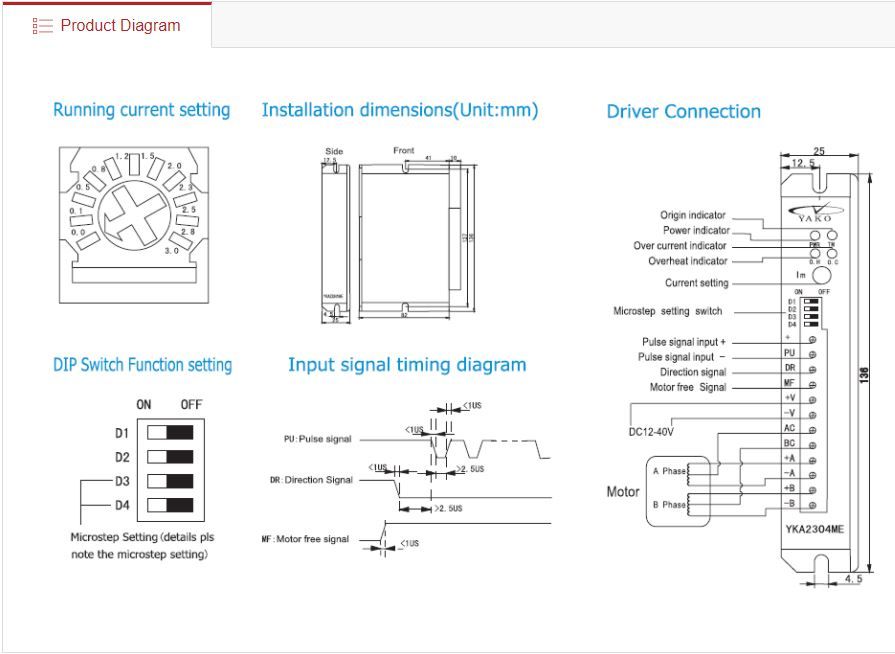
                        From Ketan's pictures the drives look as if they are the same as in the KX3, which would be logical as I guess you wouldn't want to have two designs. If they are the current is set by a screwdriver-operated control just below the screw terminal strip.

                        yako_drive.jpg

                        The top left diagram shows the switch in close-up, from looking at its setting you can see what the current is set to at the moment. With this drive the maximum setting is 3 amps. This is the YKA2304ME, an alternative the YKA2404MA/B can supply 4A/phase. If the current setting is close to these maxima the scope for an experiment to increase the current is limited.  Interesting that the manufacturer torque rating for the motor is less than what Ketan quoted.  

                        Edited By John Haine on 30/01/2022 19:08:39

                        Edited By John Haine on 30/01/2022 19:11:36

                        #583179
                        JasonB
                        Moderator
                          @jasonb

                          Though looking at Ketan's photos it looks a longer motor, more the size of the next one down the list which is 76mm long compared with the mount @56.4mm sq so could be the 1.35Kn even though the label says it's 56mm long

                          Edited By JasonB on 30/01/2022 20:09:34

                          #583186
                          Adam Stevenson
                          Participant
                            @adamstevenson91624

                            The KX3 has 3+1 with 3 higher powered drivers and the KX1 has 4 like the 1 in the KX3 lower powered drivers.

                            The fact Mike has adjusted the gib is where to start, remember these KX machines are not able to use a spanner to overcome a misadjustment.

                            Also before swapping drivers about check that the connectors are nipped up, avoid over tigening them as that can strip the thead.

                            "The Mk1 motor has an in-built torque adjustment device called the Mk1 brain cell" so just because it works by hand cannot mean it is fine.

                            photo_1_.jpg

                            Edited By Adam Stevenson on 30/01/2022 21:14:19

                            #583299
                            mick
                            Participant
                              @mick65121

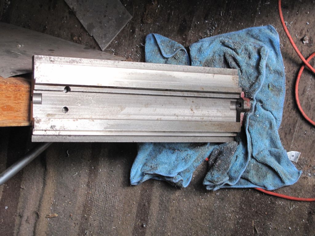
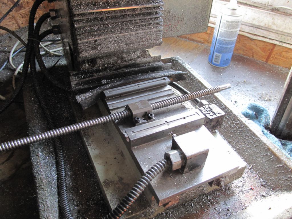
                              kx3.jpgkx2.jpgHello again. This morning I removed the stepper motor when it became clear how to remove the slide, which I did and totally cleaned all slideways and the ball screw. I coated the ball screw in Moly lub and worked the screw back and forth to get all the balls coated, at this point the ball screw moved freely. With all the slide ways coated with slide way lub I re-assembled the slide, introduced the gib and adjusted until the slide moved freely to both limits with only light hand pressure. When the ball screw was re-introduced the slide became stiff and would even jog across the 100mm area it did before. the stepper works when away from the machine. Options are narrowing.kx1.jpg

                              #583300
                              John Haine
                              Participant
                                @johnhaine32865

                                Does the slide run free with the ball screw installed and "back drive" (i.e. push the slide and the screw rotates)?

                                But it sounds like something is misaligned when you couple the motor up. Dismantle, clean and re-lube the Oldham coupling?

                                #583314
                                Ketan Swali
                                Participant
                                  @ketanswali79440

                                  Oldham couplings (not flexi-couplings) are designed to deal with mis-alignment, and do not introduce any stress on the motor or the ball screw. Usually they do not need lubrication. There is an acetyl disc in between the couplers.

                                  Difficult to figure out what mechanical issue is causing the bind.

                                  Ketan at ARC.

                                  #583316
                                  JasonB
                                  Moderator
                                    @jasonb

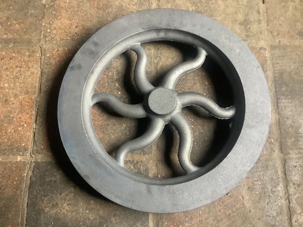
                                    Hardly seems like 15 months ago I was posting about making a flywheel pattern here. Well I've just seen a photo of the fruits of my labours.

                                    20kg of iron and 15" dia

                                    bryston flywheel.jpeg

                                    #583317
                                    John Haine
                                    Participant
                                      @johnhaine32865
                                      Posted by Ketan Swali on 31/01/2022 13:29:47:

                                      Oldham couplings (not flexi-couplings) are designed to deal with mis-alignment, and do not introduce any stress on the motor or the ball screw. Usually they do not need lubrication. There is an acetyl disc in between the couplers.

                                      Difficult to figure out what mechanical issue is causing the bind.

                                      Ketan at ARC.

                                      Agreed, but that relies on them being free. I was just hypothesising that if the motor wasn't quite lined up and the coupler binding it could push the screw out of alignment.

                                      #583327
                                      Ketan Swali
                                      Participant
                                        @ketanswali79440
                                        Posted by JasonB on 31/01/2022 13:34:45:

                                        Hardly seems like 15 months ago I was posting about making a flywheel pattern here. Well I've just seen a photo of the fruits of my labours.

                                        20kg of iron and 15" dia

                                        bryston flywheel.jpeg

                                        Looks good and clean.

                                        #583331
                                        Ketan Swali
                                        Participant
                                          @ketanswali79440
                                          Posted by John Haine on 31/01/2022 13:38:46:

                                          Posted by Ketan Swali on 31/01/2022 13:29:47:

                                          Oldham couplings (not flexi-couplings) are designed to deal with mis-alignment, and do not introduce any stress on the motor or the ball screw. Usually they do not need lubrication. There is an acetyl disc in between the couplers.

                                          Difficult to figure out what mechanical issue is causing the bind.

                                          Ketan at ARC.

                                          Agreed, but that relies on them being free. I was just hypothesising that if the motor wasn't quite lined up and the coupler binding it could push the screw out of alignment.

                                          I think I understand and agree. It may be possible that the acetyl disc could have worn over time, and or it maybe catching.

                                          Also, when the stepper motor was disconnected from the ball screw and if was free running okay without being coupled to the screw, how easy was it to stop it by hand?

                                          Ketan at ARC

                                          #583346
                                          mick
                                          Participant
                                            @mick65121

                                            Hi. John.

                                            With the stepper removed the slide does move with hand pressure but not as freely as when the ball screw isn't connected to the slide, I can however move the slide quite freely with just finger and thumb by rotating the square on the ball screw which would suggest that the gib is correctly adjusted. With the stepper reconnected there's no jog just a slight jerking movement. Everything should be in line as the ball screw mounts are doweled to the ends of the slide and no matter where ever the gib is situated the rear dovetail will align the slide.

                                            #583360
                                            John Haine
                                            Participant
                                              @johnhaine32865

                                              Well it sounds like it's the motor or driver then. Do you have a multi-meter? If you made a careful note of the connections to the driver, then disconnected the motor leads and made resistance measurements, it should reveal if there's a motor problem. It's the bottom 6 connections on my second picture above, assuming that the steppers have 6 wires which they seem to have from Ketan's photos. If you could measure the resistances and post them it would be very helpful.  Note that they will be very low, it's continuity we are looking  for.  So the A+ to A- resistance should be low, likewise B+ to B-.  There should be an even lower resistance from A to AC; and B to BC.  Any of the A connections should have infinite resistance to any of the B connections.

                                              Edited By John Haine on 31/01/2022 17:27:43

                                              #583384
                                              Adam Stevenson
                                              Participant
                                                @adamstevenson91624

                                                Mick, while the stepper motor is removed from the screw just try joging the axis, the motor should turn freely in air.

                                                #583387
                                                Adam Stevenson
                                                Participant
                                                  @adamstevenson91624

                                                  Nice patten Jason

                                                  #583415
                                                  mgnbuk
                                                  Participant
                                                    @mgnbuk

                                                    Mick,

                                                    Have you checked the cable from stepper drive to stepper motor ? With the cable disconnected at both ends, check for continuity of each line + check for shorts between lines.

                                                    I have had X axis servo motor cables fail on 2 Cincinnati Sabre VMCs at work – the first went open circuit on one line & the second the inner & outer insulation failed & the lines shorted (which took out the drive amplifier & power supply ). In both cases the cable insulation (PVC) had gone hard and brittle, compounded by Cincinnati electing to use "cheap" cable outside the manufacturer's specification (too tight bends, not rated for continuous flexing & not oil resistant) – but they both outlasted the warranty !

                                                    Further to JH's motor wiring checks above, also check from each motor wire to the motor case – all should be very high (near infinite) resistance. If you connect each pair of coil wires together, one pair at a time (A+ to A-, then B+ to B-, with the motor disconnected from the drive) the motor shaft should become much stiffer to turn than with all the wires disconnected.

                                                    Nigel B.

                                                    #583487
                                                    mick
                                                    Participant
                                                      @mick65121

                                                      First off thanks for everyone's input. I have to confess that most of the electronic stuff is way outside my comfort zone. I did say earlier on that the stepper rotated when disconnected from the machine, I tried it again this morning and I can't stop it rotating with hand pressure which would indicate that there's torque there. So with the slide moving freely with only light hand pressure without the ball screw connected, but appreciably stiffer when it is connected, although it will move with only finger and thumb pressure on the ball screw square, but the jog won't move it, could it be this torque adjuster brain cell that Adam was talking about a few posts back?

                                                    Viewing 25 posts - 301 through 325 (of 383 total)
                                                    • Please log in to reply to this topic. Registering is free and easy using the links on the menu at the top of this page.

                                                    Advert

                                                    Latest Replies

                                                    Viewing 25 topics - 1 through 25 (of 25 total)
                                                    Viewing 25 topics - 1 through 25 (of 25 total)

                                                    View full reply list.

                                                    Advert