Further Adventures with the Sieg KX3 & KX1

Advert

Further Adventures with the Sieg KX3 & KX1

Viewing 25 posts - 276 through 300 (of 383 total)
  • Author
    Posts
  • #540442
    Jimmeh
    Participant
      @jimmeh

      A slight variation on Jasons approach would be to create a sketch with 6 points on the hole centres. You can then stick a drill through the stock at these locations in CAM to obtain the correct starting material.

      Edited By Jimmeh on 18/04/2021 22:07:03

      Advert
      #541553
      JasonB
      Moderator
        @jasonb

        With the Stuart Victoria out of the way it was time to continue the adventure and do some more work on the 11cc Wall engine.

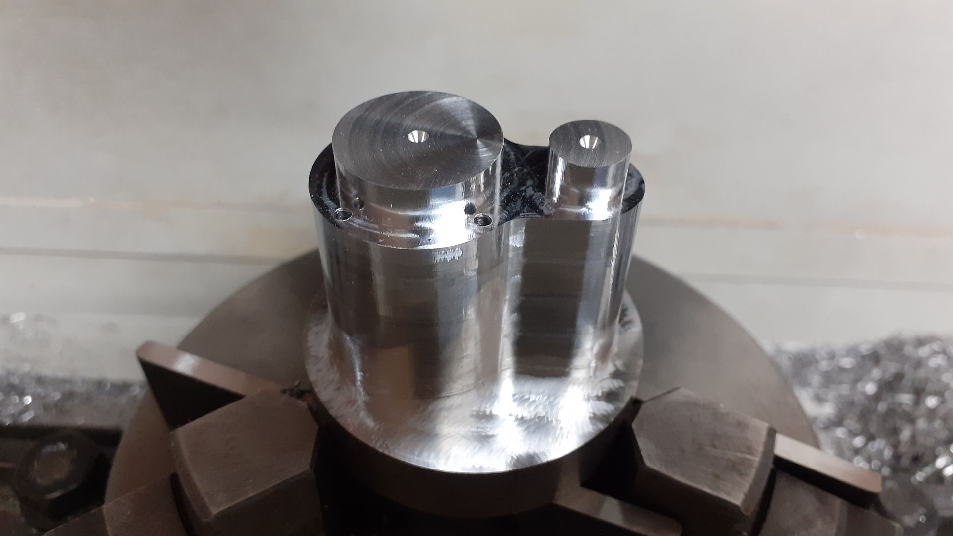
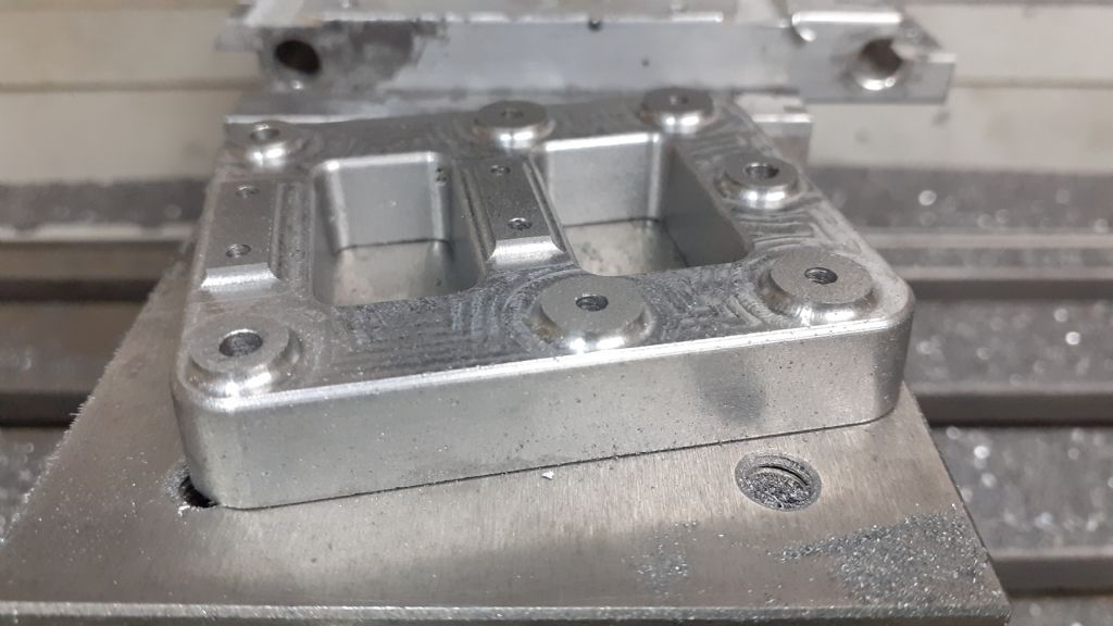
        I'll do a full write up at some time but this shows some of the work on the cylinder. Starting with some 50mm EN1A in the manual lathe it was faced and rough bored and the fins cut which was quite complex as each fin is a different diameter so the tapered sides vary on each.

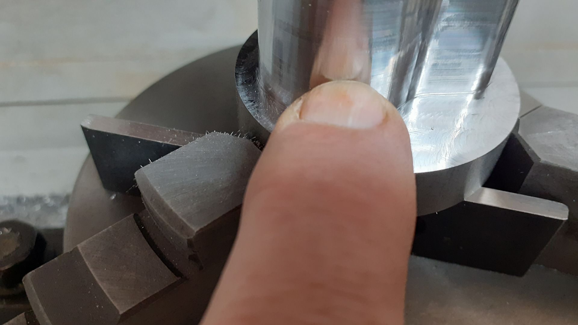
        Then onto the CNC to first rough out and finish the bottom flange and also add the screw holes at the same setting. With that done the cylinder was repositioned onto it's side to cut out a shaped pocket to accept the manifold flange (there is a simpler one on the other side too) Then so 30mm round bar was shaped to fit the cut outs, I found they were a little tight so tweaked the CAM by entering the tool diameter as 5.95mm rather than 6.0mm so it took off a fraction more material which allowed the bosses to be tapped in with a small copper hammer. I think the tool was deflecting slightly in the internal corners due to the larger engagement plus I was cutting a bit deeper than the flutes when profiling the boss – you can see the top 2-3mm is duller and not reflecting my finger as well.

        Finally back to the manual machines to curve the inner faces of the bosses before silver soldering it all together after which it was finish machined. Last job was a quick sandblast to clean it up as my well used pickling acid tends to leave the steel with a copper coating.

        #541674
        Ron Laden
        Participant
          @ronladen17547

          Nice work Jason as usual.

          I notice that the tool is climb milling its way around the part is that something that is a normal approach with CNC or is it for a better finish less tool loading etc..?

          Ron

          #541681
          JasonB
          Moderator
            @jasonb

            Very common on CNC work, I do it almost all the time and machine/tool sounds a lot happier doing it that way

            #546329
            Nicola Casali
            Participant
              @nicolacasali98042

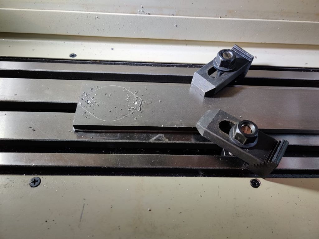
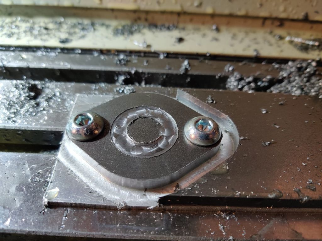
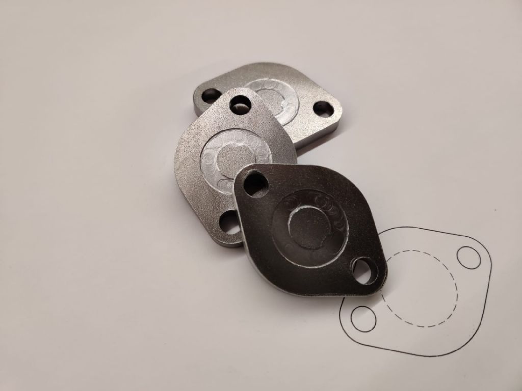
              I made these a few weeks ago with Aspire, before I got started with F360 CAM. I had to go really slow with multiple depths and used lots of coolant.

              JasonB, I can see your contouring above is quite slow too. What depth of cut are you taking?

              I tested some contouring with F360 a few days ago with no mist or coolant and got my 6mm carbide bit to glow wonderfully. My feeds and speeds were massively optimistic. Cutting a slot in steel is a completely different ball game, obviously.

              Stock workholdingFlange contouringFlanges

              #546344
              JasonB
              Moderator
                @jasonb

                Assuming you are talking about the cuts on the Wall cylinder flange then I tend to take a different approach and for your parts would have drilled first and then screwed then to some scrap so I could get all round them and like the cylinder flange first used a 2D adaptive to remove the bulk of the waste. For that I used a 3-flute 6mm carbide cutter at 4500rpm, 350mm/min feed and 1.0mm stepover, flange is 5mm thick so 5 x 1 per pass. left 0.3mm stock

                I then did a contour all round with a 4mm 3-flute carbide 5000rpm, 300mm/min feed 0.2 roughing and 0.1mm finish. Feed was a bit slower due to internal corners increasing the cutter engagement and did not want to get chatter.

                Both of these the bottom of the cutter can be set below the bottom of the work so you can use more of the edge of the cutter even if the end has become worn.

                For a cut out like you have done then with a 6mm 3-flute I'd be more in the region of 4000rpm 300mm/min feed 0.75mm stepdown and a clean up on final depth. Ramping into the cut rather than plunging and setting the lead out inline with the cut that way you won't get that nasty half moon in the edge of the central raised area that I can see or risk snapping the tool on deeper contours as it moves away into solid metal

                #546349
                Nicola Casali
                Participant
                  @nicolacasali98042

                  Sorry, I was referring to https://youtu.be/HWVk5nqtSXc

                  I just realised I used F360 for the flanges. I may have attempted Aspire first. The stock is 6.35mm. I was using a 1mm stepdown with a 4 flute endmill. I'll try your suggestions, as I need to make 3 more. Great!


                  Edited By Nicola Casali on 22/05/2021 16:00:45

                  #546352
                  JasonB
                  Moderator
                    @jasonb

                    Ah that was one of the first things that I did when I got the KX3 and was still learning. This one from from a couple of months ago has a 4mm cutter moving at 300mm/min twice the speed of that 6mm one.

                    #546356
                    Nicola Casali
                    Participant
                      @nicolacasali98042

                      I've tried tabs, but got some nasty vibrations with my non-centre cutting endmills. I don't think it's ramping into those tabs, for some reason. I tried triangular ones.

                      Edited By Nicola Casali on 22/05/2021 16:17:48

                      #546360
                      JasonB
                      Moderator
                        @jasonb

                        Thats another reason for doing it the way I tend to as the tabs can cause a bit of chatter and are the limiting factor when it come sto feed though the triangular ones are better and ramp speed can be set to less than cutting speed.

                        You should be able to do your parts the full 1/4" depth with 0.75 to 1mm stepover on the 2D adaptive, say 4500rpm and 300mm/min if 3-flute, 400mm/min if 4 flute. You can always over ride the speed if it sounds happy and try a bit faster

                        #546606
                        JasonB
                        Moderator
                          @jasonb

                          With another member making tentative steps towards CNC cutting a conrod and recent talk of adaptive and contour cuts I made this video of this mornings efforts.

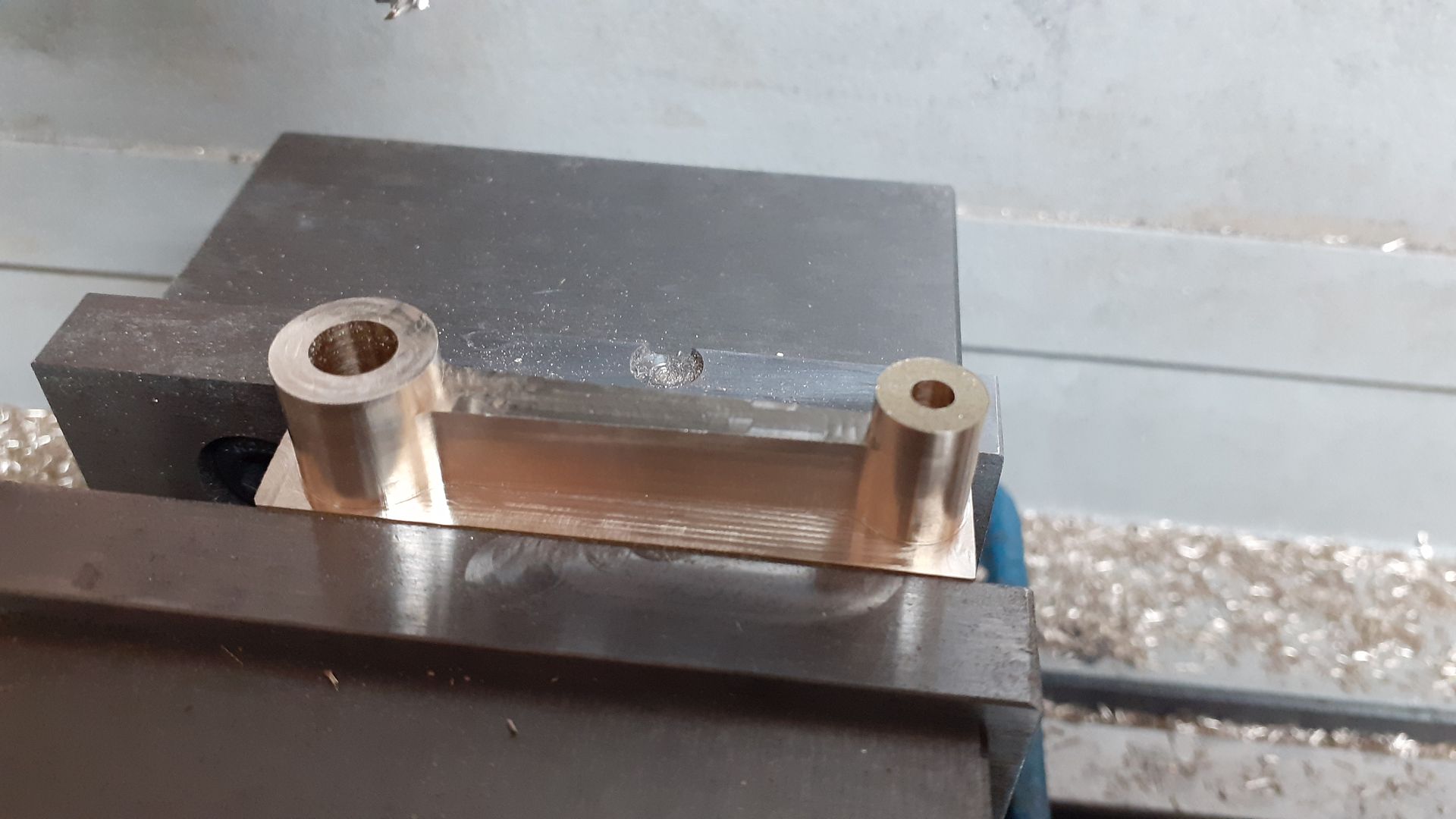
                          It's the conrod for the 11cc Wall engine I have been working on, some manual work had already been done machining up the two halves bolting together which also entailed reducing the rod width so that counterbored could be drilled for the cap head screws which have to go in from the small end and the two holes had also been drilled and reamed.

                          When doing the CAM I also picked up on the two diameters and used them to locate some holes to drill the scrap used to hold the part at the correct spacing and subsequently tapped these by hand with a 3mm spiral flute tap. Using some top hat bushes the blank was secured ready for machining.

                          First an adaptive to remove the majority of the waste then a contour to do the outer shape. Followed this with a radius corner cutter to form the two bosses and then a 3mm ball nose for the recess in the side of the rod. at 6.08 in you can hear the sound of the cut change as a bit of ali welded onto the tool as it took a full width cut so a quick reduction in feed and a dab more paraffin just managed to save the day, the other side cut fine using the slower rate from the start. Full details of cutters/feeds/DOC etc in video description.

                          #567079
                          JasonB
                          Moderator
                            @jasonb

                            One of the members of MEM forum has just upgraded his machine to a 1.1Kw teknomotor HFspindle and posted some test cuts with it, I queried the 18,000rpm that he was running the HSS cutter at and an interesting discussion about HSS/Carbide and various feeds and cuts followed. You will need to register to see most of the images which are posted as attachments if you are not already a member

                            This lead me to sacrifice a bit of 6082 to see how quickly I could convert it into a pile of chips.

                            As I have mentioned before I tend to use 3-flute cutters most of the time so this was no exception and I chose an Aluminium specific one from APT with a 55degree Helix that had had some but not too much use.

                            They give some suggested parameters for side cutting of 13,000rpm and 1,500mm/min feed so working that back to my maximum spindle speed of 5000rpm gives a feed of 577mm/min. They don't give how large the side cut can be but most other makers seem to suggest an Ae (sideways feed) of 0.1 D so I went with this making each pass 0.6mm. Ap (vertical Depth) of side cutting seem to either be given at 1D or 1.5D so I went half way with 1.25D which equates to 7.5mm. I drew up a simple block 2" (51mm) wide with a 0.6 x 7.5mm rebate in it and produced the code to cut that at various Fz (chip load) values and simply altered my Y axis zero by 0.6mm each time to compensate for the previous cut. Once I got to 500mm/min I just used the override to increase in steps of 20% eg 100mm/min.

                            For the first few cuts I just dabbed on a bit of paraffin but for the 800m/min and above also turned on the air as I was having problems getting the fluid to flow with the air. and being an external cut the chips were doing a reasonable job of staying away from the cutter anyway.

                            At no time did the machine seem to be under any strain, there was a bit of vibration on the 450mm/min pass but that was from the chip guard rather than the cutter. I stopped at 1000mm/min as I did not want to push too much and risk metal welding to the cutter or worse. Even at the highest feed the finish was quite good for what is a roughing cut with a fine series of vertical lines that could be seen when held to the light but not felt with a finger nail.

                            I'm not sure how often I will run at 1000mm/min as it will depend on the job as to any increases in cutter engagement or getting the chips out if a small pocket is being cut but it is nice to know what the machine can handle.

                            I put video and an image of the cut surface together with the feed rate son a video, couple are not the best for focus and I also mucked up the 600 & 700 videos but there was nothing exciting to see there anyway.

                            #567124
                            Ron Laden
                            Participant
                              @ronladen17547

                              Wow Jason those feed rates are impressive, at the 1000mm/min blink and you would miss it plus the surface finish looked very good to me.

                              Ron

                              #567141
                              Martin Connelly
                              Participant
                                @martinconnelly55370

                                I was trying to cut a simple step with a Little Hogger in some aluminium at 500mm/min and Mach3 detected a fault and stopped. Reset it and tried 400 then 300 then 200 and it kept stopping. Thought something was overloading the machine but finally traced it to a dodgy wire on a limit switch being upset with the vibrations. I fixed it and finally cut the step. The first time you set up something at these high rates makes you a bit twitchy but is satisfying when it works. I have not tried 1000mm/min as I am not sure my top speed is set to go that high.

                                Martin C

                                #567148
                                JasonB
                                Moderator
                                  @jasonb

                                  I can understand the vibrations with a little hogger being 2-insert and negative rake, there will be a lot more of an interrupted cut than a 3-flute cutter with the 55deg helix angle as that is engaged in the work for a lot longer per rotation. I've even noticed it of the 2 insert APKT holder.

                                  #568530
                                  JasonB
                                  Moderator
                                    @jasonb

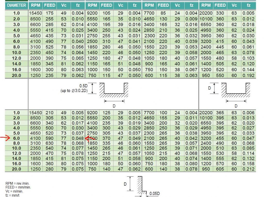
                                    I had a pressing little job for another forum member that needed cutting from some 20mm thick EN3 steel so thought I would have a play with the feed rates. The cutter is once again a 6mm 3-flute carbide one this time made by New Century which is YG-!'s Chinese factory and it has had quite a lot of previous use on steel and iron. I have attached their speed and feed chart but as the first set of figures is for carbon and alloyed steels upto 1000Nm and I was only cutting a low carbon steel I upped the spindle speed to 5000rpm and also increased Ae (sideways feed) to 0.1D or 0.6mm. Ap (height of cut) was 5.5mm which suited the 20mm thick workpiece giving 4 passes with the tool finishing below the bottom of the work piece.

                                    nc mill.jpg

                                    First pass was at 300mm/min, then using the override which goes up in steps of 10% 450mm/min, then 510mm/min which gave a Fz (chip load) of 0.034mm which it seemed more than happy with and I should think 600mm/min x 6.0mm Ap quite possible but that can be tested on some scrap. At the end of each piece there was no noticeable increase in the temperature of the work and what heat was in the tool was only slight and likely to have come from the spindle rather than the cutting end so looks like the chips were carrying away all the heat as they should. I was cutting dry with no air as chips were getting thrown well clear of the work.

                                    The adaptive cuts were set to leave 0.2mm stock which was removed with a finish pass at 200/min, You can see that the first 5-6mm of the tool that had been worn is leaving a dull finish but as the less used upper flutes make contact they are giving a brighter finish. This is only visual as I can't feel any difference

                                    Can you tell what it is yet?

                                    #573243
                                    JasonB
                                    Moderator
                                      @jasonb

                                      A bit more peeling steel this week.

                                      Started with a 2" dia piece of EN1A (230M07) steel and did most of the work on the CNC. The initial adaptive and contour around the main shape was done with an over length 8mm dia 3 flute cutter as that was the smallest I could find with 30mm long flutes as the sides are 27mm tall. With the whole part being 32mm I also had to feed a bit slower due to 35mm of tool stickout from the collet to stop any chatter.

                                      Then change to a 4mm 3-flute to do a second adaptive around the spigots as the gap was too small for anything larger and then the same tool to contour the spigots.

                                      A couple of ctr drill holes to clock in when boring on the lathe and while I was at it 2.1mm tapping holes for the M2.5 fixings that will hold it to the entablature (part is being machined upside down)

                                      Then I did the Entablature from some 5mm thick EN3. Adaptive with a 6mm 3-flute then contours with a 4mm 3-flute to get into the corners.

                                      Before removing the part from the machine I tried the cylinder, it felt like it would be a press fit which was a bit tighter than I wanted so I tweaked the contour to think it was using a 3.98mm dia cutter and ran it again, this effectively took 0.01mm off the face of the two holes and that was just enough to make it a push fit that assembles by hand yet won't drop off.

                                      I also did the cam while I was at it but did not bother to film that.

                                      #573265
                                      Ian Johnson 1
                                      Participant
                                        @ianjohnson1

                                        The cylinder is impressive Jason, it's a big ask of a small diameter cutter to get a good finish that deep, especially on steel.

                                        I might try out my KX1 and see what it can do, it's a sturdy little machine but not quite up to the KX3.

                                        IanJ

                                        #573431
                                        JasonB
                                        Moderator
                                          @jasonb

                                          Yes I was quite pleased with how it turned out but looking back I should have taken the oppertunity to try a couple of full depth finishing passes which could easily have been done if I had left a bit more stock from the initial adaptive clearing, maybe next time.

                                          It's smoother than it looks and as it is going to get something else silver soldered to it and the sqbsequent cleaning up from that then painted more than adequate.

                                          The last major bit for that engine was the conrod which I did yesterday morning and had it running by the end of the day.

                                          #576159
                                          JasonB
                                          Moderator
                                            @jasonb

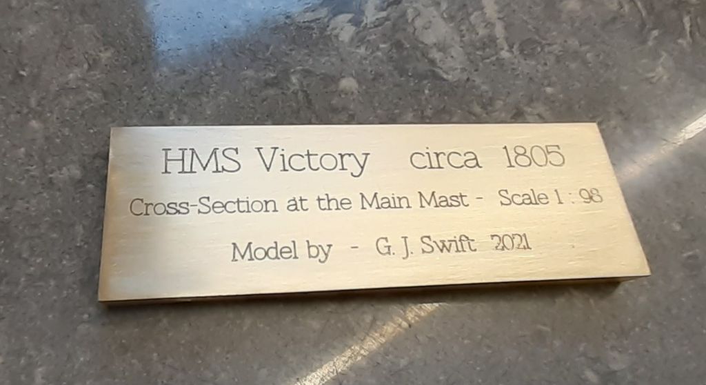
                                            I finally had reason to use the engraving cutters I bought almost 18months back from Sorotec in Germany

                                            A good friend who is into building model ships finally finished one and as well as asking me to make the display cabinet also mentioned a plaque to go with it and I said I would see what I could do.

                                            Size was to be no more than 80mm wide which dictated the font size which ended up being 2.5mm high for the lower two lines and 4mm for the top one. I used the pointed single flute 60degree cutter and as the width of the lines meant it was not going in much deeper than 0.12mm the actual largest diameter was in the region of 0.1mm which meant a fairly slow feed of 50mm/min with it spinning at my max of 5000rpm to try and not damage the cutter.

                                            As the DOC was so shallow I took a 0.2mm skim off the top of the plate first with a 63mm face mill fitted with inserts intended for non ferrous to ensure the cuts were all the same depth from the top of the work.

                                            I'm quite pleased with how it came out, run time was a bit slow as using the free F360 combined with a slow feed rate meant the rapids were rather sluggish too but I was able to leave the machine to it and get on with other things while it did it's stuff.

                                            I also did a bed plate for the next engine from a block of cast iron at the weekend, adaptive with a 6mm dia cutter 6mm x 0.6mm cuts and finish 3D contour with a 4mm dia cutter with 1mm corner radius, 0.2mm stepdown as all the verticals have 3deg "draft" angle and fillet around the bosses is 1mm radius. Finish is good enough to go straight to paint.

                                            #582530
                                            mick
                                            Participant
                                              @mick65121

                                              I posted a few days ago about my problem with the control of my KX1 stalling and loosing its reference position. One suggestion was that the slide ways could be sticking, which after some 2800 running hours was a distinct possibility. After removing the X axis gib, a complete clean and applying copious amounts of ptfe slide way spray I put it all back together and after several hours of fine adjustment achieved about 50mm of smooth jog in both the + & – directions when the cross slide is centrally positioned after which the slides jammed, this is quite possibly due to thirteen years of wear, however the slide moves smoothly to the limits when rotating the ball screw via the square on the end. I can only think the main problem might be the stepper motor not being man enough to drive the slide after the re-assembly. Another stepper motor would not be that expensive but I can't find anything on the cross slide stepper that tells me its torque as I would want to get a slightly more powerful one as a replacement, so I'm sure someone out there will be able tell me what the torque of the current motor is and maybe be able to suggest what sort of torque I should be thinking about as a replacement. Thanks.

                                              #582534
                                              John Haine
                                              Participant
                                                @johnhaine32865

                                                Mick, I think you should try to make sure that you don't have an electronics problem before diving in to replace the motor. For example the PSU may have started to produce a lower voltage, or the stepper drive is starting to fail. I can't think why a stepper would degrade provided it hadn't been dismantled (which would reduce the magnetism). I would check the supply voltage to the drivers (when moving), check all the current settings on the drives etc.

                                                By the way, it's quite likely that the motor is being driven d=below it's max rated current so provided the PSU has the capacity you could try tweaking the current setting switches on the drive to increase the current – a quick was to see if more torque would help.

                                                #582831
                                                mick
                                                Participant
                                                  @mick65121

                                                  Hi. John.

                                                  Thanks for your input, electronics is a bit of a closed book to me, if I can't solve a problem mechanically I'm lost, so with this in mind how would you suggest I go about tweaking the current settings? Thanks.

                                                  #582836
                                                  John Haine
                                                  Participant
                                                    @johnhaine32865

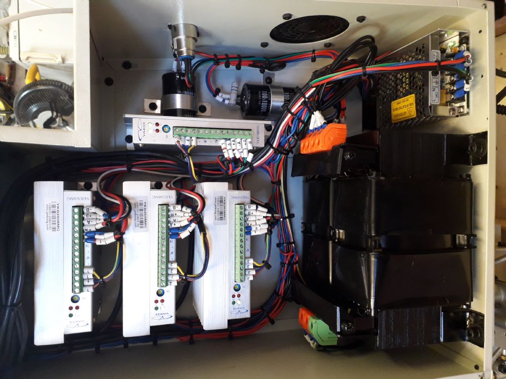
                                                    Can you get into the control box that houses the stepper drives and take some close-up photos of the top of them (or can someone who has a KX1 do this) please? The drives are usually black boxes about 100 x 40 x 80 high. On the top they will have a row of terminal blocks with cable connected, and a set of little switches that are used to set the microstep ratio and current. There may also be a type number on the drive that could well be something like 2M542 which were quite common when the KX1 was on sale. By comparing the switch settings with the data sheet one can see what the current is set to and what headroom there is to increase it.

                                                    I must emphasise that increasing the current would only be to determine if there is a possible torque problem, I wouldn't recommend just fitting a new motor in the hope it will improve matters, you need to find out what the underlying issue is.

                                                    Where are you located?

                                                    #582844
                                                    JasonB
                                                    Moderator
                                                      @jasonb

                                                      may be silver boxes with heat sinks if the KX3 is anything to go by,Yako make

                                                      20190223_150415.jpg

                                                      Edited By JasonB on 28/01/2022 18:30:25

                                                    Viewing 25 posts - 276 through 300 (of 383 total)
                                                    • Please log in to reply to this topic. Registering is free and easy using the links on the menu at the top of this page.

                                                    Advert

                                                    Latest Replies

                                                    Viewing 25 topics - 1 through 25 (of 25 total)
                                                    Viewing 25 topics - 1 through 25 (of 25 total)

                                                    View full reply list.

                                                    Advert