Further Adventures with the Sieg KX3 & KX1
Further Adventures with the Sieg KX3 & KX1
- This topic has 396 replies, 38 voices, and was last updated 2 May 2025 at 21:06 by
 Sarah F.

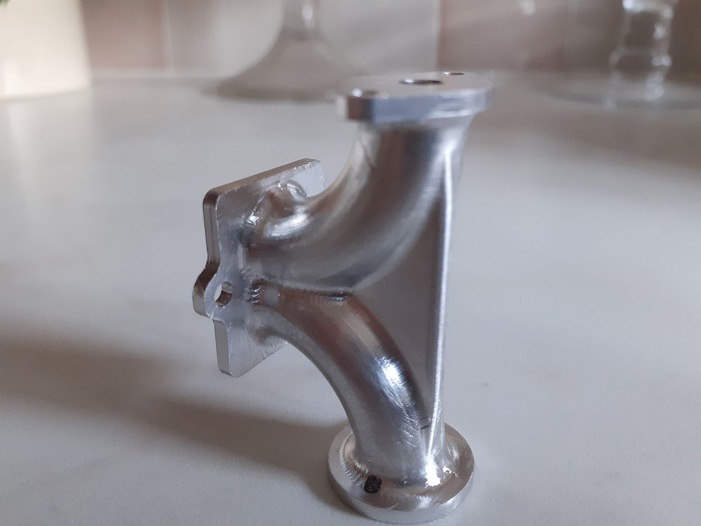
![20200727_122720[1].jpg](/wp-content/uploads/sites/4/images/member_albums/44290/872026.jpg "20200727_122720[1].jpg")


- Please log in to reply to this topic. Registering is free and easy using the links on the menu at the top of this page.
Latest Replies
-
- Topic
- Voices
- Last Post
-
-
Sanjay’s Banjo Engine
Started by:
JasonB
in: Stationary engines
- 3
-
12 July 2025 at 16:20
JasonB
-
Silver steel crankshaft
Started by:
teamricky
in: Stationary engines
- 3
-
12 July 2025 at 16:04
Diogenes
-
“swedish iron”
Started by:
moonman
in: Materials
- 11
-
12 July 2025 at 15:41
moonman
-
Electronic leadscrew pitching error
Started by:
paulg 1
in: Introduce Yourself – New members start here!
- 2
-
12 July 2025 at 15:26
JasonB
-
Nozzle dot dwg
Started by:
Michael Gilligan
in: CAD – Technical drawing & design
- 1
-
12 July 2025 at 14:47
Michael Gilligan
-
TurboCAD – Alibre File Transfers.
Started by:
Nigel Graham 2
in: CAD – Technical drawing & design
- 5
-
12 July 2025 at 14:28
IanT
-
Another Day … Another ScumBag
Started by:
Michael Gilligan
in: The Tea Room
- 12
-
12 July 2025 at 14:27
V8Eng
-
The Silver Swan Automaton
Started by:
James Alford
in: Related Hobbies including Vehicle Restoration
- 2
-
12 July 2025 at 12:47
Michael Gilligan
-
Help for DIY lathe build.
1
2
Started by:
moogie
in: Help and Assistance! (Offered or Wanted)
- 16
-
12 July 2025 at 12:38
noel shelley
-
New Member From The Isle of Man
Started by:
sprocket 3
in: Introduce Yourself – New members start here!
- 3
-
12 July 2025 at 12:33
noel shelley
-
Sat nag
1
2
Started by:
duncan webster 1
in: The Tea Room
- 16
-
12 July 2025 at 12:30
noel shelley
-
Yet another scam
Started by:
Dell
in: The Tea Room
- 2
-
12 July 2025 at 10:16
Bo’sun
-
buying machine tools from aliexpress experiences?
Started by:
Jake Middleton-Metcalfe
in: Manual machine tools
- 14
-
11 July 2025 at 22:26
Versaboss
-
Adjustable spanner thread direction
Started by:
jimmy b
in: Workshop Tools and Tooling
- 8
-
11 July 2025 at 22:14
Nimble
-
Chester Champion, warco ZX15 drawbar
Started by:
martian
in: Manual machine tools
- 5
-
11 July 2025 at 21:51
Howard Lewis
-
Bosch PBD 40 bearing upgrade
Started by:
th1980
in: Manual machine tools
- 6
-
11 July 2025 at 21:33
Howard Lewis
-
Square end on round stock – Milling?
1
2
Started by:
Roger TheShrubber
in: Workshop Tools and Tooling
- 17
-
11 July 2025 at 21:23
Howard Lewis
-
motor and switch wiring Myford ML7
Started by:
1957jmh
in: Workshop Tools and Tooling
- 4
-
11 July 2025 at 21:09
Howard Lewis
-
I’m Under Pressure
1
2
Started by:
howardb
in: Related Hobbies including Vehicle Restoration
- 16
-
11 July 2025 at 19:12
Nealeb
-
Farm Boy
1
2
…
4
5
Started by:
Dalboy
in: I/C Engines
- 15
-
11 July 2025 at 18:48
Diogenes
-
Old plastic handled screwdrivers
Started by:
Dave Halford
in: Workshop Tools and Tooling
- 12
-
11 July 2025 at 17:14
Robert Atkinson 2
-
Bridgeport ways and wear
Started by:
inline
in: Manual machine tools
- 7
-
11 July 2025 at 09:16
Ian Owen NZ
-
Maisie lubricator
Started by:
ferroequinologist
in: Locomotives
- 9
-
11 July 2025 at 09:09
Clive Foster
-
Transwave converter – plugged in motor, tripped RCD
Started by:
ell81
in: Beginners questions
- 8
-
10 July 2025 at 22:56
Master of none
-
Eight Trains
Started by:
Vic
in: The Tea Room
- 1
-
10 July 2025 at 14:14
Vic
-
Sanjay’s Banjo Engine


