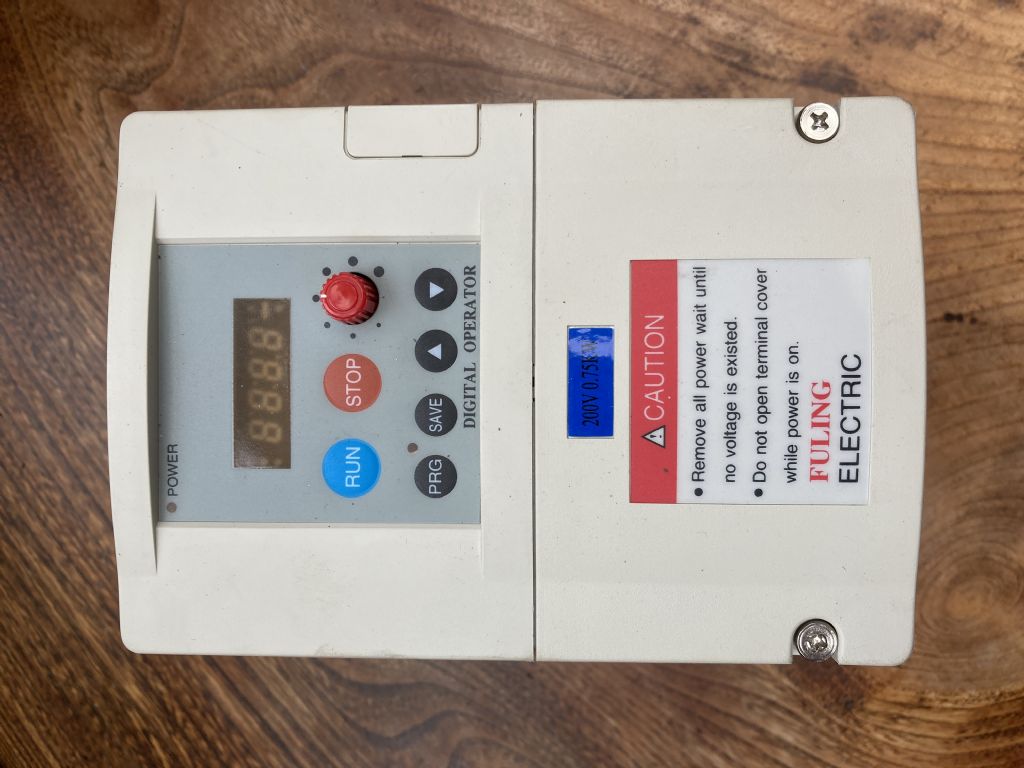
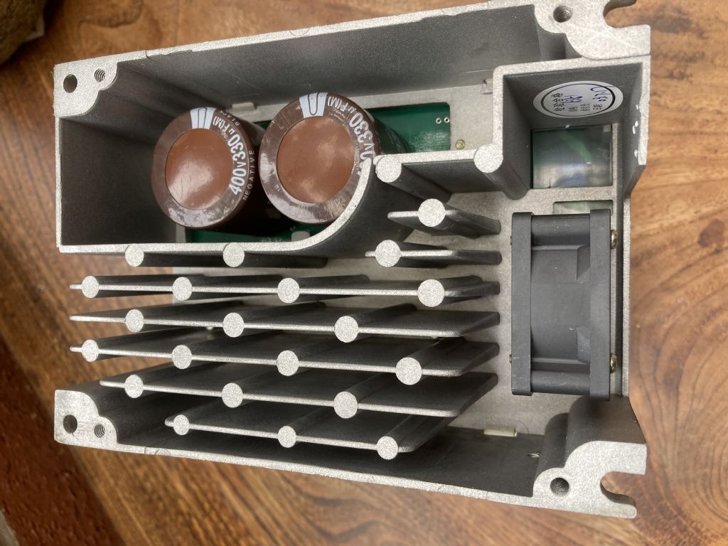
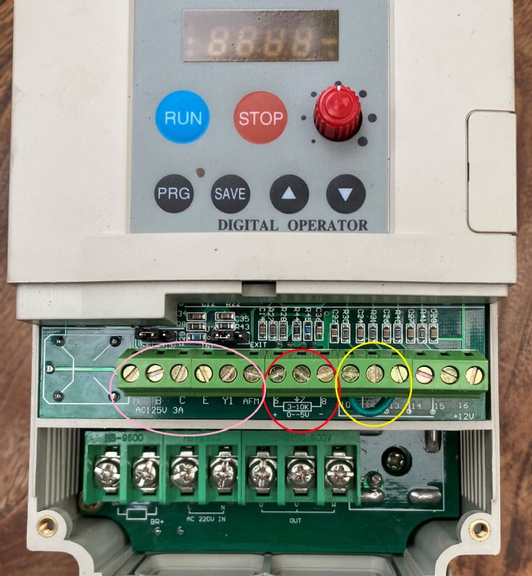
Sorry to resurrect this thread but I'm stumped for the wiring of the remote controls for this VFD.
I managed to find and download an operators instruction manual for the DZB100 variant, which seems to be a higher spec unit with more controls on the in built keypad, specifically in addition to RUN and STOP the 100 model has FWD, REV, JOG and more flashy lights!
I managed to wire up my 3 phase motor (U,V,W connections ) and brought in the single phase supply to the L and N terminals and to keep the 'Elfins 'appy I also connected the earths. Switched it on and pressed start – motor ran as expected after a short ramp up of around 2 secs, 50.00Hz displayed on the readout. Pressed stop and motor ramped down. So far so good.
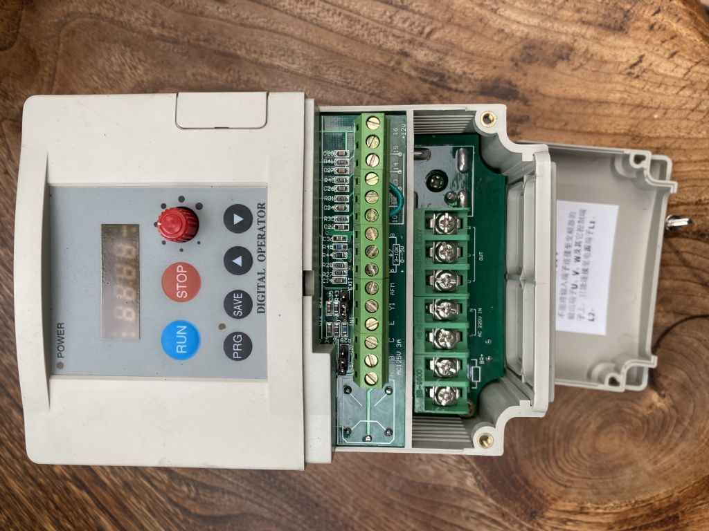
Looking at the terminals shown below, there are what I assume to be the potentiometer connections circled in red. Fairly straight forward with a feed, signal (wiper) and signal ground. This will give me a remote speed control. No question here!

Going now to the terminals circled in Yellow – these are numbered L to R as 10,12,13, 14,15, &16 (oddly no number 11 ) As will be seen 10 and 13 are linked and again I am assuming this is a hard wired 'FWD' connection but I am at a loss as to how to identify 'REV' and 'JOG' – my logic tells me linking 10 to 12 may reverse the motor, presumably 10 to either 14.15. or 16 will JOG. Or 2 of that combination may be 'set speed 1, set speed 2'
The terminals circled by the Lilac highlight are a bit of a mystery, Basically what are A, B, C and E liable to be? AFM I understand from the DZB100 manual is for a Analog Frequency Meter (quaint thing! ) but a Digital meter can be used from this connector by 'bit' change in the Function programme. Could the lettering 'AC 1 25V 3A' conceivably be a LoVo light output??
The terminal Y1 is a mystery – is it Y as in 3 phase connection for 220V??
Any ideas would be gratefully received, I have a Fluke DVM to analyse the signals. A selection of switches, lights and buzzers to complement an RS aluminium remote box connected all by Raychem 66 shielded wiring is waiting to be wired up. Just need to work it all out!
BTW – there is a 10V – 5V jumper just to the top left of centre of the Lilac circle. Currently set at 10V
Martin
Oily Rag.


