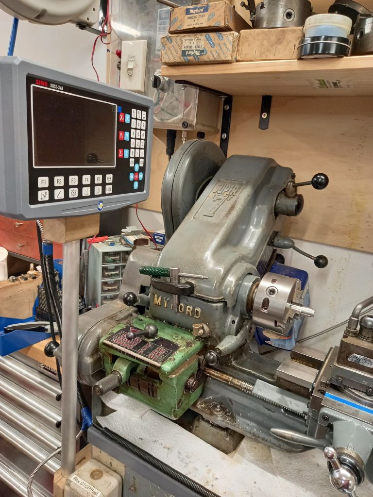
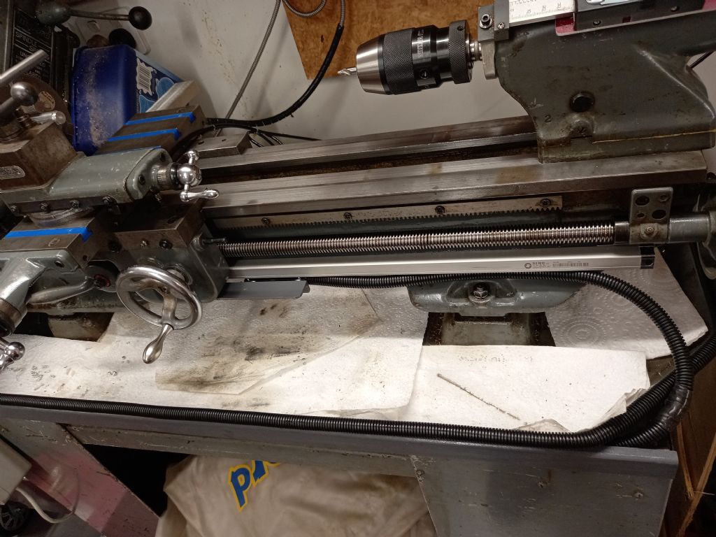
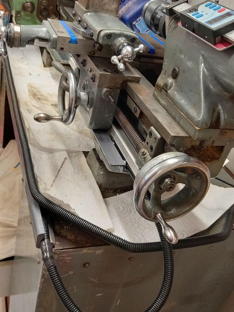
So I have finally went and did a magnetic 1um read head and embedded magnetic tape. Also installed a miniature series 1um K200 Sino linear scale in the front of the lathe. This will allow me to still use the taper turning attachment although I have not yet mounted it to be sure.
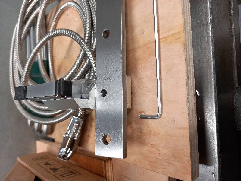
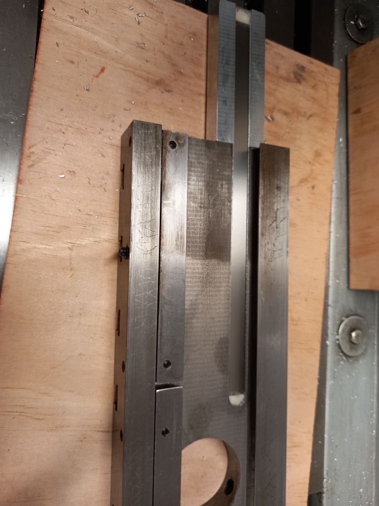
First was the install of the cross slide scale , and took a bit of work to achieve, with adding an aluminium extension block similar to what is done with other embedded tape systems. On mine, the block is flush with the top side of the slide, but is made 0.8mm higher on the under side. I did this as a guide for installing the rear reader head. The block that holds the reader head, is mounted on the rear carriage plate, or shear. The milled slot is 10.6mm wide for easy install of the tape and the ends were filled with glue with a filler. The filler was to let the reader wipers to not get damaged from any sharp lip or edges.
The most difficult was the install of the front miniature K200 series scale. The scale itself is only 16mm wide and 16mm high. The reader head is around 14mm wide and the total height is 32mm from the bottom of the read head to the top of the scale. To my surprise, it is acceptable to have the whole unit mounted on its side , even with coolant splash from the top. But clearly can't take sideways coolant from anything with pressure. So mine is mounted vertically with the read head down. I made a template from 25mmx3mm mild steel to see how it would all fit etc. I soon realised that the biggest consideration was the halfnut height when Not engaged, and then the ability to remove the saddle front gear box assembly. The halfnut needs to be fully in front of the linear scale body. I also needed to access the fixing screws of the reader head and at the same time needed to be able to remove the protective covers on the read head once it was secured to the carriage.
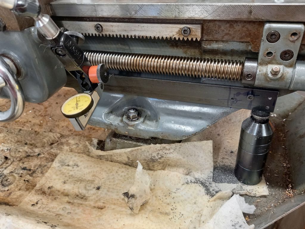
With all these things being considered I set about the mounting and drilling and tapping into the casting. Each side end will be needing shims to level each of the mounting end plates anyway. I used screw jacks on each end to get it running level with the run of the saddle, and drilled the left hand end reference drill and tapped it M4 and secured it for the mean time. Then removed the scale and drilled and tapped the right hand end holes from the template and then did the left hand end holes from the template. I then cut up the template and counter sunk the holes for M4 screws and milled the surfaces parallel and flat on both sides. Placed the pad pieces onto the bed and went ahead to level them up in line with the run of the bed and then vertically using a square and a block. After much shimming and messing around got them to an acceptable runout of better than 0.03mm with the run of the bed and looking like not much light from a square and a 75mm long block placed on the pads. One thing that I did not consider until mounting the scale back onto the pads were there position for how far apart they were spaced. I got lucky and it fitted for the hole spacing, but after the various shims the pads were the correct height for the scale being parallel as well. I had envisioned that were going to be made to get this adjustment right as the areas of the casting had around 0.3mm difference is in being parallel with the bed.
The next stage was the reader head mounting bracket. Originally it was going to be connected to the bolt of the thread dial indicator that I rarely use. But then decided to mount it from the underside of the front casting. That was set up in the mill and the area was cut parallel with the top of the casting and 2 M5 screw to secure the angle iron that was going to be the reader mount plate. I milled a parallel reference on the angle iron and that was a good thing, as I was originally going to make the front edge flush with the castings milled edge. I then remembered that doing so would make the removal of the plastic protective covers almost impossible. The piece of angle iron was milled square etc and mounted onto the bottom of the casting and aligned to be parallel. The holes were drilled and tapped to suite the height of the reader head holes and spot faced on the back side of the material. It was painted and then reassembled in place again. The apron was assembled onto the carriage after it was all cleaned with a new wiper installed. The holes matched really well and then needed to measure the distance between the reader head and the plate. I used a small cheap gauge block set to do this. 2.0mm was the correct size, so made 2 spacers 13mm diameter 2mm thick. Assembled and removed the plastic pieces and all went well. Still some little cover extensions and pieces I am going to make. They will be held inplace with just some double sided tape so they can be easily removed for cleaning.
Neil Lickfold.


