From the ground up!

Advert

From the ground up!

Home Forums Work In Progress and completed items From the ground up!

Viewing 22 posts - 76 through 97 (of 97 total)
  • Author
    Posts
  • #406460
    Nigel Graham 2
    Participant
      @nigelgraham2

      Hello John.

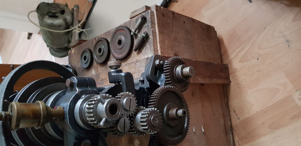
      Those gears are the change-wheels, changeable to give different ratios between the spindle and the lead-screw (which you called a "drive screw&quot for cutting screw-threads of a range of pitches.
      To give the widest screw-cutting range for the machine and the normal change-wheel set supplied with it, they are arranged to be set in single-layer or as you say, two-layer ("compound&quot configurations.

      On many lathes the change-wheels are also used to give a uniform, fine surface, as well as for screw-cutting.

      That pinion pair just below the spindle wheel is for reversing the lead-screw relative to the spindle rotation, so you can cut left-hand threads.

      I'm not sure what the two "ears" protruding from the main bearing carry though.

      Good to see you've put the poor old lathe back into decent condition!

      Advert
      #406461
      Nigel Graham 2
      Participant
        @nigelgraham2

        Done it again! Forgotten certain punctuation marks give those silly wink etc symbols!

        #406480
        JohnM
        Participant
          @johnm51917

          20190425_190644.jpg

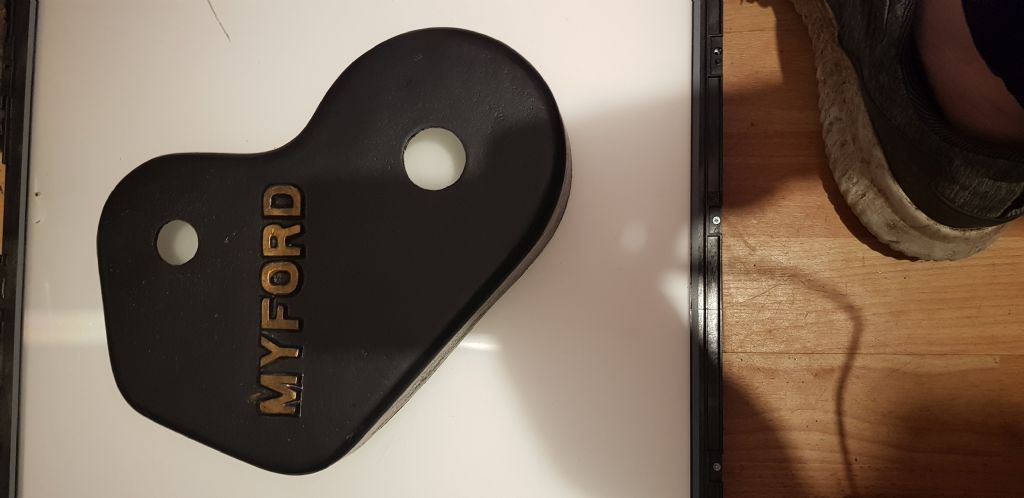
          This is the cover and I'm now convinced it is not from this Lathe. I have seen another one near to this shape but with a cutout for the shift lever. The smaller cover that covers the headstock gears fouls and again there is a rounded version that would possibly fit. The one I have is shaped and has two raised sections like a pair of t.. two hump back bridges.

          Nigel your posts look far more friendly with those silly winks 👌

          Brian, you have been a massive help to me and while I have enjoyed putting this old Lathe back to its former glory it's time for another project for me. I am severely limited on space so have to be ruthless. I hope you can give me some more advice and pointers on my next project.

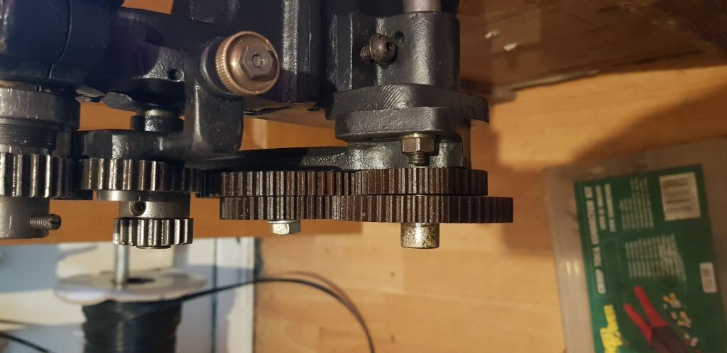
          Q. Photo below, is there a spacer as it is not reaching out to the second gear?

          20190425_191355.jpg20190425_191844.jpg

          #406481
          not done it yet
          Participant
            @notdoneityet

            If you think about it, there must be two “layers” (or more) to change the ratio for sufficient options. A single layer, moving one tooth would turn every subsequent gear by one tooth, too (although there are obvious changes in direction of rotation). So that only provides different output speeds depending on the first and last gear sizes. Not too convenient!

            The increased number of different ratios are effected by one sized gear directly driving a different sized gear on the same shaft. In certain cases, the extra layer could be of a different pitch. This is often the case for gearboxes with very hig ratios – the high speed gears are of small pitch and the low speed (high torque) gears of much sturdier teeth.

            Nigel,

            You can edit your post within a certain timed period. It is rather more than a couple of minutes.

            #406489
            Nicholas Farr
            Participant
              @nicholasfarr14254
              Posted by not done it yet on 26/04/2019 09:32:45:


              Nigel,

              You can edit your post within a certain timed period. It is rather more than a couple of minutes.

              Hi, yes you normally have about 30 minutes to edit your post. Just click on edit post in the green bar at the top of your own post.

              Regards Nick.

              P.S. you can also edit your post several times in that time period, but be sure to delete your previous edit notifications at the bottom of the page, makes it look tidier.

              Edited By Nicholas Farr on 26/04/2019 10:06:09

              #406609
              Nigel Graham 2
              Participant
                @nigelgraham2

                Thank you for the tip, Nick.

                '

                John,

                Re your Question about spacers.

                A bit difficult to see from the angle of that photo, but the gear set does look a bit odd. I assume one of the wheels on the lead-screw is acting only as a spacer, well clear of the one opposite it.

                The change-wheels should run on specially-made stub-axles often called "studs", with a threaded spigot on the inner end to go through the long slot in the banjo (the long arm), and be secured by a suitable washer and nut.

                The banjo also has two radial slots so it can be swung to mesh different diameters of wheel.

                With only one intermediate stud, as you show, you can use only 2 meshed pairs: pinion + CW1, CW2 + CW3. (CWs 1 and 2 are pinned together on the stud.)

                Following approximately the set-up shown, number the change-wheels 1 to 3, in driving order from spindle to lead-screw. Assuming only one of the lead-screw wheel in the picture is actually meshed, with the other just being a spacer….


                As set there, the drive pinion following the reverse tumbler pair should mesh with the first change-wheel, so that would have to be stood off the banjo face by a longer stud.

                I am not familiar with the ML4 (mine is an ML7) but my guess is that the stud would have a large flange on it which both helps it sit properly on the banjo face, and places the change-wheels in the correct planes. As you have it there, all the change-wheels are a displaced inwards by a gear thickness.

                On the ML7, the change-wheels are put on hardened, keyed steel sleeves of length fractionally double one wheel thickness, and which run on the studs. The wheels have matching key-ways.

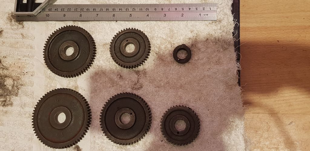
                Your photo of the 5 wheels and spacer shows they are keyed together instead by small mild-steel pins set into the holes clear in the photo. (The Drummond lathe uses the same arrangement.) I don't know if the intermediate wheels on your lathe run on similar sleeves or directly on the studs.

                To erect the required train with single intermediate stud; once you've selected the wheels for the appropriate overall ratio:

                The drive pinion engages CW 1.

                Lower the banjo to give you room to work on it.

                Thread CW 2 first onto the first stud (or sleeve & stud) on the banjo, with a spacer behind it if the stud is not flanged, so the plane of its outer face is just behind that of the drive-pinion's inwards face.

                Thread CW 1 onto the same stud, outside of CW2, with the driving-pin connecting them. (In practice it might be easier to pin them together first but the result is the same.). This should put CW1 and the drive pinion in line.

                Fit the nut and washer, or screw and washer, on the stud's outer end to keep the wheels in place. Move the assembly towards the banjo slot's outer end, out of the way, for the moment.

                Now set CW 3 onto the lead-screw with a spacer to ensure it is line with CW 2. There should be a grub-screwed spacer to hold the wheel on the shaft, and that spacer will also have a pin for keying to the wheel hence the shaft: yes, it is there, in the photo.

                I don't know from the photo above if the grub-screw engages a keyway or shallow hole in the lead-screw end, hidden by being ""round the corner". It should do, to avoid bruising the lead-screw.

                Now slacken the stud and the banjo nuts just enough to move things about. This is where having plenty of room to stand at the end of the lathe helps, as the next step can be fiddly.

                Gently swing the banjo upwards while manipulating the intermediate stud, until each wheel meshes with its intended partner. They should run properly when the teeth are engaged with just light hand pressure. Nip the stud nuts and banjo nuts, test the set-up by turning the machine gently by hand (with the motor unplugged!); and when happy tighten them enough to hold the gear-train together in use.

                Spacers: you can use a spare change-wheel as a spacer BUT ensure it won't foul another wheel and jam the lot up.

                Well, that's found your first task for this lathe – making a proper intermediate stud and change-wheel spacers!

                '

                If you're setting this up to cut a thread, measure the first cut when it is no more than a fine scratch to ensure your change-wheel sums are right. (If you don't have the chart for the lathe.

                '

                (Or even if you do – yes, you've guessed how I know! I was using a Harrison L5 that caught me out with its feed-range gear-box.)

                Edited By Nigel Graham 2 on 26/04/2019 22:34:18

                #406628
                JohnM
                Participant
                  @johnm51917

                  I just realised what those 'studs' nuts and bolts are in my left over box. Thank you for the complete and in depth reply. I'm back on it today. More settling and pics to follow. I'm not putting any punctuation at the end that turns into funny faces but I am 'down with the kids' and may do if I get to the finish line this weekend.

                  #406629
                  JohnM
                  Participant
                    @johnm51917


                    20190427_075250.jpg20190427_075243.jpg

                    Edited By Neil Wyatt on 29/04/2019 23:00:43

                    Edited By Neil Wyatt on 29/04/2019 23:01:04

                    #406630
                    JohnM
                    Participant
                      @johnm51917

                      Just about jiggling the gears about till something clicks. I have seen photos of two gears besides each other so will try to achieve that. Why is there no blueprint with the configuration laid out for lazy people? :funny laughing face:

                      #406633
                      Howard Lewis
                      Participant
                        @howardlewis46836

                        Hi John!

                        It doesn't look as of you have a complete set of changewheels.. I would have expected to find two 20T gears and then the others going up in 5 tooth increments to a final 65T.

                        The gears are driven by Driving Collars, (You should have two, one for the Mandrel, and one for the Leadscrew ) which drive the gears by the 3/32" pins, and lock to the flat on the shafts by 1/4 BSF grubscrews. The gears are aligned with each other by means of spacing collars, either inside or outside, as required.

                        The gears are compounded by 3/32 diameter pins inserted into the drilling in the gear. the drilling does not go right through, to stop them falling out. Gears from ML7s will fit (Same bore, Diametric Pitch and Pressure Angle&nbsp they just need a 3/32 hole drill half way through. Mount, on one of the gear studs ( from the banjo ) one of the original gears and drill tight through into the ML7 gear. Avoid the keyway in the 7 Series gear! You should then blank off part depth of the hole in the original gear.

                        The gears must have backlash, to avoid nolse and wear. Run a sheet or two of writing paper into each mesh before tightening the stud to the Banjo; starting at the Mandrel.

                        You can use the Leadscrew to provide a power feed for turning, if you wish. The finest feed that you can get will be 20:60/20 (Compound on Stud 1 ):65/20 (Compound on Stud 2 ):60 (on Leadscrew ). This should give you a feed rate of just over 0.004"/rev.

                        The tumbler reverse will decide whether the Saddle moves towards, or away from the Chuck.

                        Incidentally, I would remove that stud and nut , and use a 5/16 BSW setscrew , (near the Leadscrew ) to clamp the Banjo, to avoid any chance of a foul with a gear on the leadscrew.

                        When you feel confident enough to think about cutting threads, (without using Taps or Dies) take a look at Brian Wood's book on "Gearing of Lathes for Screwcutting". Your lathe has a 8 tpi Leadscrew, although I suspect that it is Right Hand thread, unlike the 7 series, (and most other lathes ) which have a Left Hand thread.

                        I think that I have already repeated what Tony Griffiths says about the Cross and Top Slide Leadscrews being 12 tpi, and each of the 80 divisions on the dials not being exactly one thou!

                        Heed his warning about removing the Grubscrew from the pulley on the mandrel before engaging Back Gear.

                        DON'T use back gear to lock the mandrel to unscrew a Chuck or Faceplate, it is a quick way of breaking teeth off the gears!

                        HTH

                        Howard

                        #406636
                        JohnM
                        Participant
                          @johnm51917

                          Thanks Howard. I will try to take all this in. I'm still getting to grips with all the terms. I am sure it will wind a few people up but we all have to start somewhere. The Lathe was even more complete than I originally thought so I haven't had to buy any bits as yet. I guess I will have to sooner or later. These Lathe strippers are ruthless on their prices. I will post how I get on tonight and once again thank you to everyone posting help it is very much appreciated.

                          #406740
                          Brian Wood
                          Participant
                            @brianwood45127

                            Hello John,

                            From memory, the gear cover at the headstock end with the two humps in it is very similar to pictures of Mickey Mouse, so I think your's is correct for ML4. The change wheel cover also looks familiar, but the last time I saw mine was >30 years ago, so don't quote me

                            Thank you for the lavish praise you have directed my way but I think it should really be aimed at other contributors, they have really taken on the baton holder's role now and with my recollections based on such a long time ago, they will be far more likely to give you reliable advice over the mounting of change wheels for instance.

                            I know you plan to sell the lathe on, but I have a comprehensive gearing pdf for 8 tpi non gearbox lathes that will include yours for a £2.50 contribution to the REMAP charity, a worthy cause that aims at making life a bit easier with bespoke gadgets for those unfortunate individuals who are handicapped in some way.

                            If you would like a copy, send me a PM with your email address.

                            Regards

                            Brian

                            #406822
                            JohnM
                            Participant
                              @johnm51917

                              I have to agree with you on your comment regarding the help received from other members here and am very appreciative of any advice given along the way. To take time out of your day to help and especially with such comprehensive replies has not only been a massive help to me it will also help others in the future with their own renovation projects.

                              As for selling the Lathe on I just don't have room to store this as my next project is already here and I am chomping at the bit to get stuck in on that one as soon as I have completed the ML2/4 I hope that this thread has rekindled memories of times with your father Brian and it hasn't been a chore to fix up this Lathe and when I get a workshop I could go the very same route again.

                              I had a box of bits delivered with the Lathe and some parts were in that were probably lying about that were just thrown in. I have a Fixed steady that is completely over sized for the Lathe purchased possibly from a Harrison or a Boxford and probably worth more than the Lathe itself. A back plate with a thread far too big again. It looks like it's painted in Myford Blue although i can't find it on the internet as yet but I'm too engrossed in the ML2/4 to give it any attention as yet.

                              I don't want to cobble something together at the last hurdle so will take you up on your offer of the PDF document. Should I pay you or make a payment online to REMAP?

                              #406845
                              JohnM
                              Participant
                                @johnm51917

                                One down, one to go

                                20190427_213829.jpg

                                #406916
                                JohnM
                                Participant
                                  @johnm51917

                                  REMAP paid via text Brian. thank you for the document.

                                  #406982
                                  JohnM
                                  Participant
                                    @johnm51917

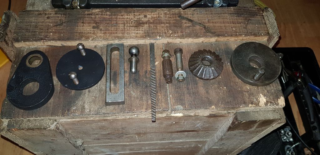
                                    You know how it is. You finish (you think) and there you are with a handful of bits left over. Any help identifying these items would be appreciated. 20190428_225015.jpg

                                    #407000
                                    Nicholas Farr
                                    Participant
                                      @nicholasfarr14254

                                      Hi John, the one on the far right is a catch plate. You put this on in place of the chuck and then use a dead centre in the spindle and dead or live in the tailstock, you then put your piece of bar between the two centres with a dog on the spindle end of the bar and this will catch on the peg on the catch plate. This is known as turning between centres. Of course you will need a centre drilled into each end of your bar. The second one from the right looks like a milling cutter to me. don't know what the rest are for.

                                      Regards Nick.

                                      Edited By Nicholas Farr on 29/04/2019 06:34:51

                                      #407007
                                      Nigel Graham 2
                                      Participant
                                        @nigelgraham2

                                        Yes – I'd say the 2nd from right is a milling-cutter, for forming chamfers and slide-way dovetails.

                                        3rd and 4th: possibly either change-wheel studs or tool-pots studs. Do they fit the appropriate places on the lathe?

                                        Number 5 looks to me like some sort of broach.

                                        6, the ball-ended pin, does not look like part of this lathe, but for something else entirely.

                                        7 (from right): it's a bit thin-walled for the task but might have been a work-holding clamp for a milling or drilling machine table, especially given the presence of that milling-cutter.

                                        8, the disc with two handles, might have been made as a handle for the lathe's top-slide. It doesn't look an original part but could have been a past owner's custom-made fitting.

                                        Finally, 9… could be almost anything! That does look like a bearing bush in the smaller end. I wonder if it was made as a secondary banjo for the lathe, to extend the change-wheel ratios possible – but that's only a guess. Like the ball-ended pin and the slotted bar, they might not be lathe accessories at all.

                                        It is possible the mystery bits were intended for some user-built accessory for the lathe, but more likely were part of some project or other. Old machine-tools acquired umpteenth-hand tend to come with useful or even important bits missing, but with an assortment of strange-looking items, odd nuts and bolts, worn-out tools and such like!

                                        I remember someone once donating my model-engineering club one of those old-fashioned, foot-cubed biscuit-tins, full of just such an assortment of small nuts, screws and odd-shaped bits of metal in fetching shades of verdigris and ferrous oxide. We tipped the lot out onto a bench to pick potentially useful from mere scrap…. Most items were innocent (and scrap) but it was just as well one club member was a police officer, for he was able to take away for proper and legal disposal, the dozen or so revolver rounds!

                                        #407009
                                        Brian Wood
                                        Participant
                                          @brianwood45127

                                          Hello John,

                                          I agree with the analysis from both Nick and Graham but would add that I don't think the catch plate would fit your lathe spindle, the central threaded hole looks too large.

                                          Regards

                                          Brian

                                          #407015
                                          Ian Hewson
                                          Participant
                                            @ianhewson99641

                                            2nd from the right looks like a valve seat refacer for car cylinder er heads, screws on to a mandrel and cuts the face of the valve seat. Usually come in sets with different angles for inlet and exhaust valves.

                                            Still have a set hiding out from when I used to play about with BMC a & b heads.

                                            Spent hours polishing the ports etc to a shine, but saw the other day from a respected head tuner that the best results came from leaving the finish as ground, as it gave better mixing of the petrol air mix.

                                            Wish I had known that 50 years ago😩.

                                            #407104
                                            Pete Rimmer
                                            Participant
                                              @peterimmer30576

                                              Second from the right is a globe valve seat cutter.

                                              #407121
                                              JohnM
                                              Participant
                                                @johnm51917

                                                Thank you everyone for your replies. I had no idea about anything apart from the Catch Plate but despite two people explaining it to me it was not until now I realise what it is. I need a dog I guess. Sorry for the late replies but after the disappointment of missing out yesterday on an eAuction a trip over to Yorkshire means I'm the proud owner of…. yes yet another Lathe.

                                              Viewing 22 posts - 76 through 97 (of 97 total)
                                              • Please log in to reply to this topic. Registering is free and easy using the links on the menu at the top of this page.

                                              Advert

                                              Latest Replies

                                              Viewing 25 topics - 1 through 25 (of 25 total)
                                              Viewing 25 topics - 1 through 25 (of 25 total)

                                              View full reply list.

                                              Advert

                                              Newsletter Sign-up