From the ground up!

Advert

From the ground up!

Home Forums Work In Progress and completed items From the ground up!

Viewing 25 posts - 51 through 75 (of 97 total)
  • Author
    Posts
  • #404052
    JohnM
    Participant
      @johnm51917

      Two of the photos Nigel. I think I deleted the duplicate files and the post with it.

      Advert
      #404075
      Howard Lewis
      Participant
        @howardlewis46836

        John,

        Study Tony Griffiths "Lathes UK" website, pages about the Myford ML1, 2,3 and 4.

        It is a mine of useful information.

        With a lathe of that vintage, all the threads should be Whit form. (i. e. The extra two tappings to clamp the swivel on the Topslide are 1/4 BSF. The Banjo is clamped with a 5/16 BSW setscrew. ) If the mandrel is 7/8" diameter, it will be either 9 tpi on earlier models, or 12 tpi on later ones.

        Early models were flat belt drive, but later ones were V belt drive, or had been converted.

        Early MLs were 3 1/8" Centre Height, but later ones were 3 1/2". I found that out the hard way; by assuming that the one I was going to help to return to service was 3 1/8". When I got to it, it was 3 1/2" and i had made a Centre Height Gauge for 3 1/8"! But the Mandrel was 7/8 x 9 tpi, so possibly a transition or field fix hybrid?

        Not all machines had Tumbler Reverse; that was an optional extra, and ones without it do not have the tappings to fit it. Although, Tony Griffiths says that some owners have managed to fit the Tumbler Reverse from a ML7.

        There are two tappings at the back of the Headstock. Those, I found out are for the cast bracket that carries the Changewheel Guard. Guards that hinge sideways are rare. Normally, they hinge upwards.

        Changewheels are compounded by a 3/32" pin in a drilling which only goes part way through the gear.  ML7 gears, with a keyway, can be used, by drilling a 3/32" hole for the pin.

        Tony refers to some machines being factory painted in "Vomit Green"!

        HTH

        Howard

        Edited By Howard Lewis on 07/04/2019 19:14:48

        #404093
        JohnM
        Participant
          @johnm51917

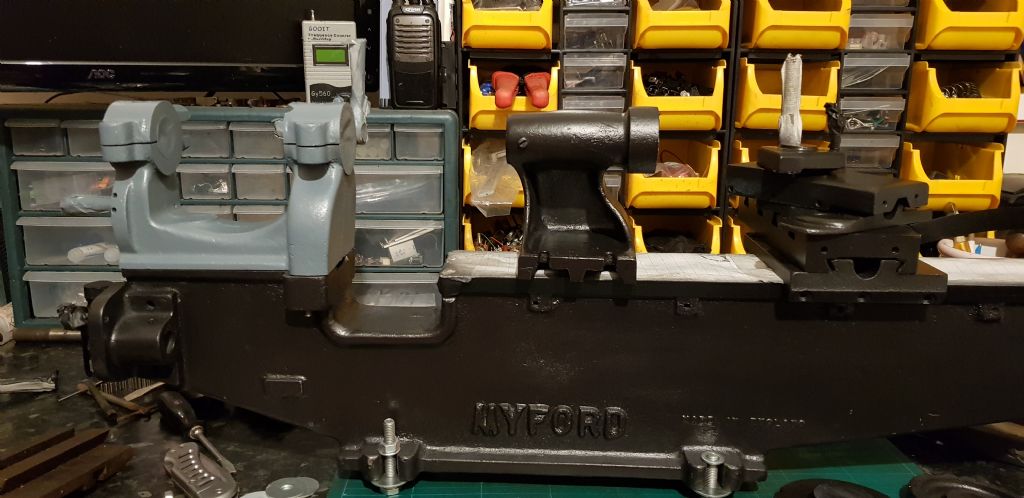
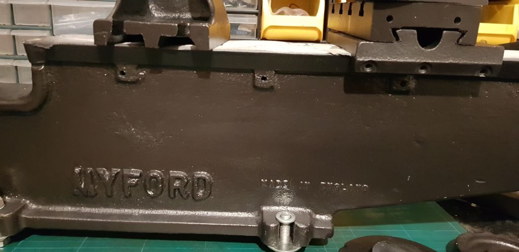
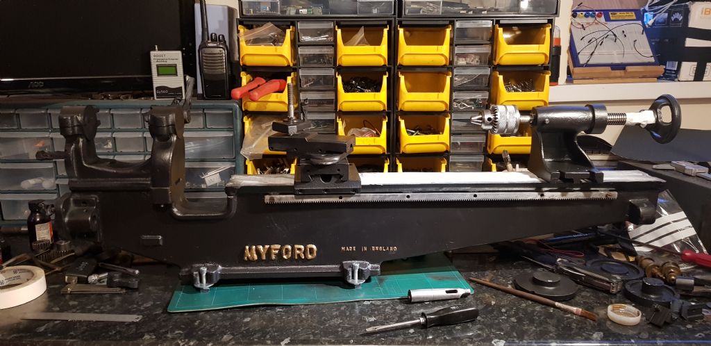
          I didn't want to go with the Myford colours nor did I want a perfect finish and too afraid to use it. I have gone with a black but the finish is like an old industrial original. Let me know what you think. All the smaller parts are going in the oven to make them heat resistant and prove them at the same time.

          20190407_203203.jpg

          20190407_203153.jpg

          Edited By John Milton 2 on 07/04/2019 21:37:50

          #404106
          JohnM
          Participant
            @johnm51917
            Posted by Howard Lewis on 07/04/2019 19:12:25:

            John,

            Study Tony Griffiths "Lathes UK" website, pages about the Myford ML1, 2,3 and 4.

            It is a mine of useful information.

            With a lathe of that vintage, all the threads should be Whit form. (i. e. The extra two tappings to clamp the swivel on the Topslide are 1/4 BSF. The Banjo is clamped with a 5/16 BSW setscrew. ) If the mandrel is 7/8" diameter, it will be either 9 tpi on earlier models, or 12 tpi on later ones.

            Early models were flat belt drive, but later ones were V belt drive, or had been converted.

            Early MLs were 3 1/8" Centre Height, but later ones were 3 1/2". I found that out the hard way; by assuming that the one I was going to help to return to service was 3 1/8". When I got to it, it was 3 1/2" and i had made a Centre Height Gauge for 3 1/8"! But the Mandrel was 7/8 x 9 tpi, so possibly a transition or field fix hybrid?

            Not all machines had Tumbler Reverse; that was an optional extra, and ones without it do not have the tappings to fit it. Although, Tony Griffiths says that some owners have managed to fit the Tumbler Reverse from a ML7.

            There are two tappings at the back of the Headstock. Those, I found out are for the cast bracket that carries the Changewheel Guard. Guards that hinge sideways are rare. Normally, they hinge upwards.

            Changewheels are compounded by a 3/32" pin in a drilling which only goes part way through the gear. ML7 gears, with a keyway, can be used, by drilling a 3/32" hole for the pin.

            Tony refers to some machines being factory painted in "Vomit Green"!

            HTH

            Howard

            Edited By Howard Lewis on 07/04/2019 19:14:48

            Thanks Howard I will have a read up now.

            #404110
            Georgineer
            Participant
              @georgineer
              Posted by Howard Lewis on 07/04/2019 19:12:25:

              … Early MLs were 3 1/8" Centre Height, but later ones were 3 1/2"…

              Howard, my understanding is that the different centre heights were according to the model, not the date (ML1, ML2 were 3 1/8", ML3, ML4 were 3 1/2&quot. My post on the first page of this thread gave details for identifying the different models.
              Of course, if you know different I am happy to be corrected.

              George

              #404116
              Hopper
              Participant
                @hopper

                ISTR GH Thomas commenting in his book about the rear toolpost that centre height had been found to vary by 1/8" or so from one machine to another of the same model. So it's more of a nominal height than exact.

                #404183
                Georgineer
                Participant
                  @georgineer
                  Posted by Hopper on 08/04/2019 01:15:41:

                  ISTR GH Thomas commenting in his book about the rear toolpost that centre height had been found to vary by 1/8" or so from one machine to another of the same model. So it's more of a nominal height than exact.

                  That sounds very likely. It would depend, among other things, how much had been planed off the bed to get a good finish.

                  Does anybody know why the closing bracket (ok, I know it's really a parenthesis) in my previous post has been turned into a daft face?

                  George

                  #404186
                  Howard Lewis
                  Participant
                    @howardlewis46836

                    Yes, Georgineer!

                    Newton's 4th law. If you leave a space between the last character and the bracket, it doesn't happen.

                    No prizes for guessing how I found out! Just have to keep remembering to hit the space bar before the bracket.

                    Not easy with my memory!

                    Howard

                    #404187
                    Howard Lewis
                    Participant
                      @howardlewis46836

                      So maybe, my pal's lathe is a ML3 not a ML2 as he thinks. I was merely regurgitating what i understood from Lathes UK, so maybe I misunderstood.

                      The main thing is to get it set up and running, now!

                      Howard

                      #404234
                      JohnM
                      Participant
                        @johnm51917

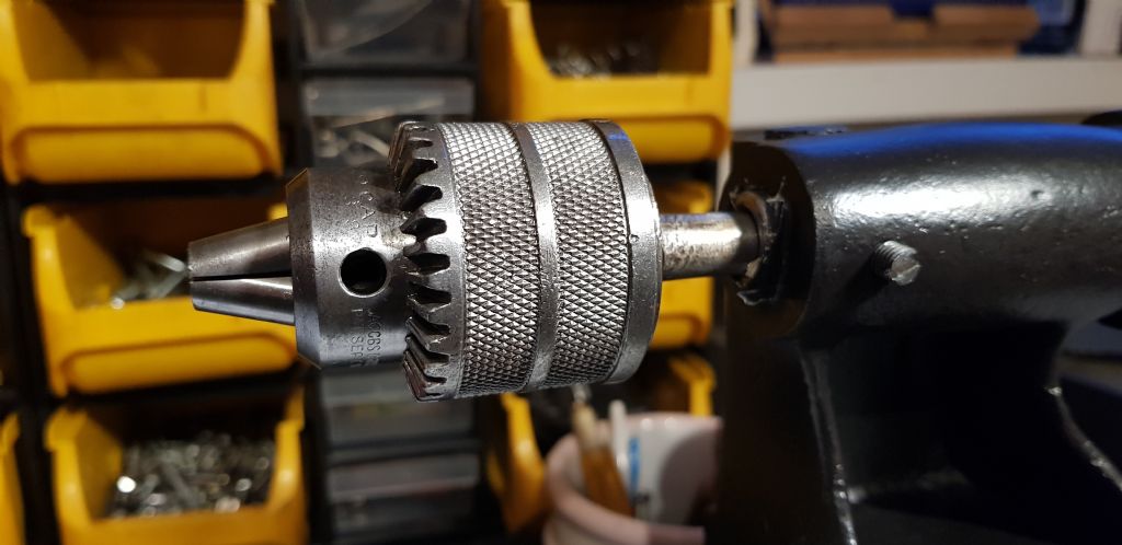
                        This Chuck was black, seized up and quite sad. That was this morning though. Rack has been cleaned and de-rusted. Just need to remember where everything goes.

                        20190408_200528.jpg20190408_200520.jpg

                        #404310
                        JohnM
                        Participant
                          @johnm51917

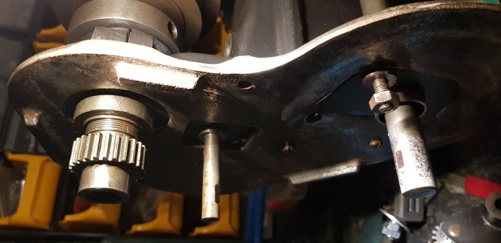
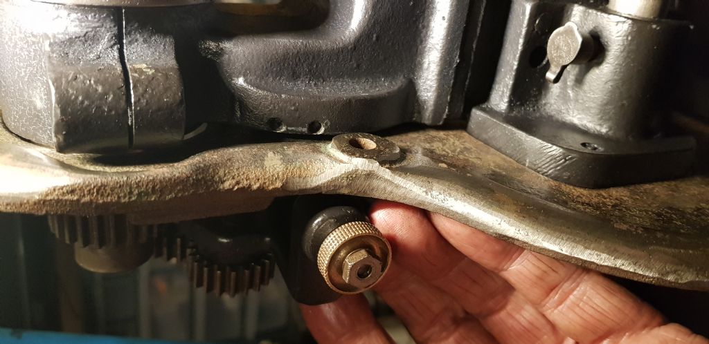
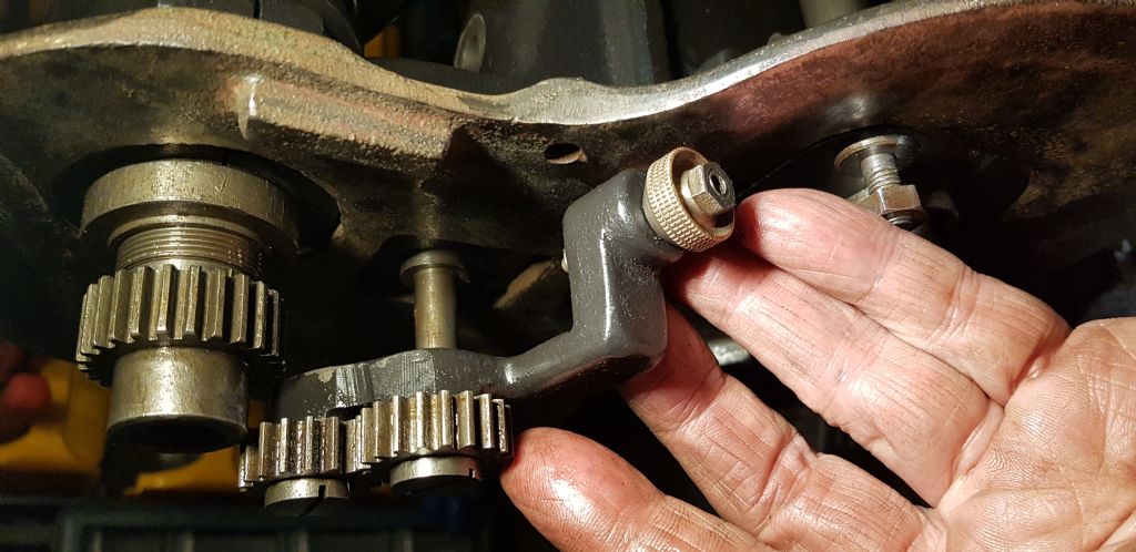
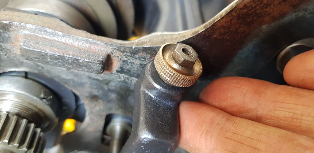
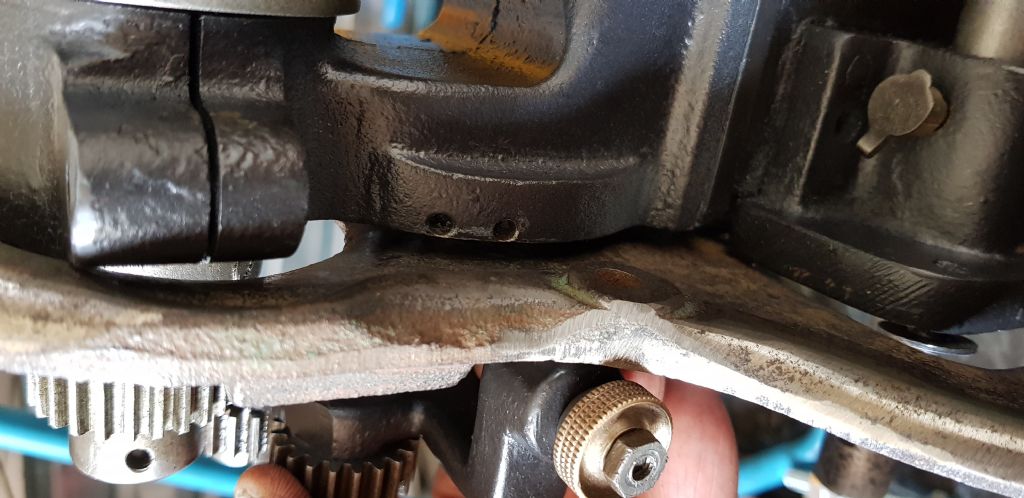
                          I seem to have hit a brick wall. I put the large mounting plate onto the end of the Lathe and found that the geared knob will not fit in place.All works well without the plate so if anyone can look at the photos and tell me what I am doing wrong I would appreciate it. If not the angle grinder is coming out!

                          20190409_015104.jpg

                          20190409_015142 (1).jpg

                          20190409_015156.jpg

                          #404317
                          Nicholas Farr
                          Participant
                            @nicholasfarr14254

                            Hi John, maybe you have to hook the geared knob over the plate first and then assemble them both together.

                            Regards Nick.

                            #404340
                            JohnM
                            Participant
                              @johnm51917

                              Thanks Nick, It must be a mismatch. I can't see how this will ever work. Will they to find some photos on G Images. #baffled

                              20190409_131733.jpg20190409_131725.jpg

                              Edited By John Milton 2 on 09/04/2019 13:52:03

                              #404363
                              Brian Wood
                              Participant
                                @brianwood45127

                                John,

                                From memory, there was a plate but much lower down for the change wheel cover to butt up to at the leadscrew. There was certainly nothing of the size you show here

                                Brian

                                #404372
                                Howard Lewis
                                Participant
                                  @howardlewis46836

                                  The detents for the tumbler reverse are on the other side of the plate. So it looks as if the Tumbler Reverse needs to be hooked over the plate before sliding the Plate and Tumbler Reverse onto the stud.

                                  In that way, the gears will mesh and the plunger will drop into the detents.

                                  Howard

                                  #404384
                                  Dalboy
                                  Participant
                                    @dalboy

                                    I am no expert but all the bits I have seen that plate does not appear on other ML4 s that I have seen around.

                                    #404397
                                    JohnM
                                    Participant
                                      @johnm51917

                                      I thought it was time to put it all together, more for damage control to find if any parts are missing, looks like it was a good plan. There are a number of parts that look like they belong but I haven't worked out where as yet. I may post some photos so you can help me with this later. You have all been a great help so far.

                                      The back plate has three screw holes that line up and fix it to the Lathe. After fitting the back plate the large Myford cover can then be fitted, screwed through the back plates reverse side and into the cover. When the cover is on there is no cut out for the switch lever which slides onto a spindle but it does line up with the exposed gears correctly so can not be placed anywhere else. I will take some photos or maybe a video would show it up better than I have done already with photos.

                                      thanks for all the help chaps tomorrow it may look a little clearer for me.

                                      Edited By John Milton 2 on 09/04/2019 23:38:31

                                      #404458
                                      JohnM
                                      Participant
                                        @johnm51917
                                        #404978
                                        JohnM
                                        Participant
                                          @johnm51917

                                          I'm down south so not working on the Lathe as such, but I have to pick your brains please. The motor mount and counter shaft are missing so I need to build my own. Metal frame with a shaft to support the top belt wheel will be the easiest. My question is as I don't have the top wheel can someone please tell me the diameter of the shaft so I can get the correct size. Also how do I put something up for sale here? Do I have to be a member for so long? I don't have the option to post in classifieds.

                                          Thanks in advance

                                          PS I may have accidentally put a deposit down on my next project. oops don't tell the missus.

                                          Edited By John Milton 2 on 14/04/2019 08:28:51

                                          #404986
                                          Brian Wood
                                          Participant
                                            @brianwood45127

                                            John,

                                            I think a countershaft diameter of 3/4 inch would be quite adequate. That suits standard sizes of plumber blocks to run it in.

                                            Brian

                                            #404989
                                            JohnM
                                            Participant
                                              @johnm51917

                                              Cheers Brian, will the pully wheel fit 3/4 inch shaft. I'm limited on what I can do here. I have a pillar drill now but mostly woodworking tools. I will have to make a frame using my angle grinder I guess.

                                              #404990
                                              Brian Wood
                                              Participant
                                                @brianwood45127

                                                John,

                                                I really don't know, until you get a pulley you can measure and even it it isn't 3/4 inch bore, that can be adjusted by sleeving or boring out as necessary. .

                                                The frame should be easy enough to build from bolted up angle iron, or even Dexion if you have it.

                                                Brian

                                                #405928
                                                JohnM
                                                Participant
                                                  @johnm51917

                                                  Had a week down south so nothing has been done on the Lathe. Back last night so I have painted a few parts and mainly been selling everything I have to get some ££ together for my next project. The little lathe has been sold on so only two Lathes here right now but THREE Lathes will be squeezed in here tomorrow.

                                                  I admittedly have very little knowledge but I have to think of how easy it will be to sell on after refurbishment as the Clarke Lathe is still here and needs to go ASAP. Space is a premium. Still can't work out how to post a sales thread here. Do I have to be a member for so long?

                                                  Thanks for all the help, watch this space…

                                                  #406407
                                                  JohnM
                                                  Participant
                                                    @johnm51917

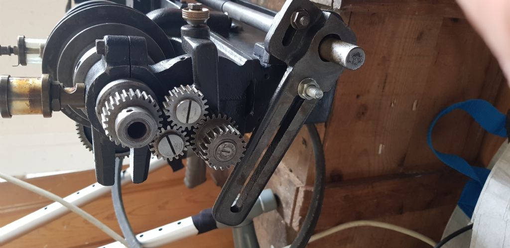
                                                    I could do with some help please. I am on the final straight and have researched online how the gears are configured to meet up with the drive screw. The gears meet up but it looks like there are two layers. If anyone can help me with a photo or instructions of which gear goes where I would be most grateful.

                                                    Thank you.

                                                    20190425_122209.jpg

                                                    #406422
                                                    Brian Wood
                                                    Participant
                                                      @brianwood45127

                                                      Hello John,

                                                      It would help us a lot if you tell us all what gears you have with the lathe, then one of us can suggest an arrangement to give a feed of some sort to the leadscrew.

                                                      As it seems you will be selling the lathe on anyway, that will be enough to test it out

                                                      Brian

                                                    Viewing 25 posts - 51 through 75 (of 97 total)
                                                    • Please log in to reply to this topic. Registering is free and easy using the links on the menu at the top of this page.

                                                    Advert

                                                    Latest Replies

                                                    Viewing 25 topics - 1 through 25 (of 25 total)
                                                    Viewing 25 topics - 1 through 25 (of 25 total)

                                                    View full reply list.

                                                    Advert

                                                    Newsletter Sign-up