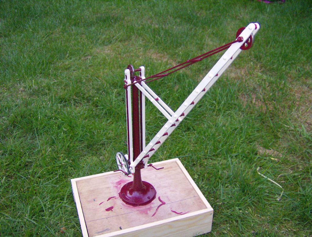
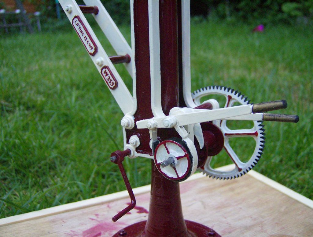
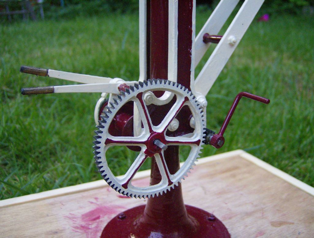
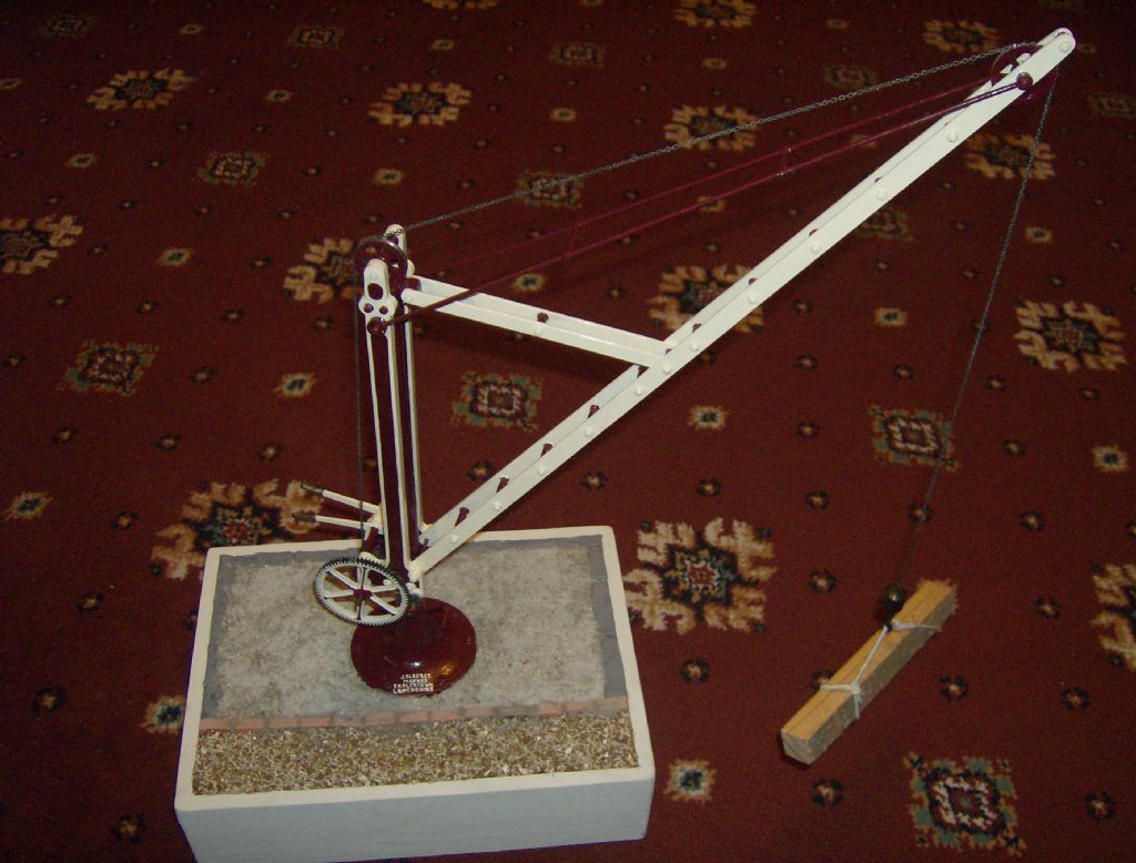
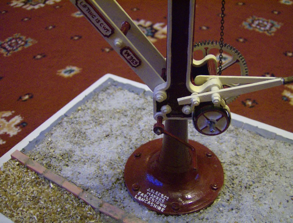
As alluded to elsewhere Neil, you should be well pleased with your labours. Congratulations then on finishing this rather unusual, well researched and accurately made model. You’ve made a lovely job of it and your attention to detail and the final presentation has produced a very realistic rendition.
I look forward to following your next unusual prototype
Question for Neil or anyone here who has built this from his plans: the jib is shown as a bit over 8" long on the plan, which is clearly incorrect based on the column height. Are the published dimensions for this 50% actual? In which case is the jib thickness still 1/16" x 1/4" or should it be 1/8" x 1/2"?
A timely thread resurrection, I have just walked the dog to Fradley Junction from home in Kings Bromley. I will look out for the original crane on my next walk.
Question for Neil or anyone here who has built this from his plans: the jib is shown as a bit over 8" long on the plan, which is clearly incorrect based on the column height. Are the published dimensions for this 50% actual? In which case is the jib thickness still 1/16" x 1/4" or should it be 1/8" x 1/2"?
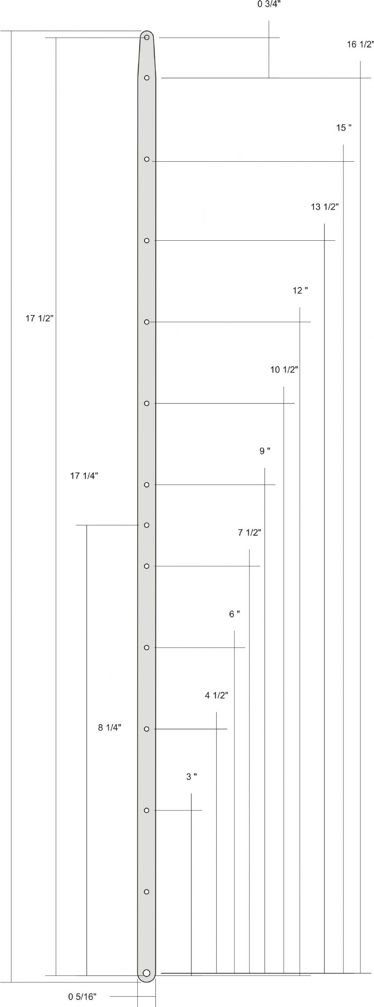
I think rogue auto dimensioning may have meant that one version of the plans had wrong dimensions when the jib was scaled to fit the page. The plans have been revised, these are the correct dimensions:
A couple of follow up questions: What's the width of the jib material? It's not dimensioned on the plan, but looks to be about 3/8" . Also, the width of the top spacer is shown as 1" while the bottom spacer is 1 1/8" . That difference would make the main frames taper slightly towards the top. Is that correct? From the photos they look to be parallel.
The two orphan dimensions should go to the holes they miss by a bit, both of which are correctly positioned if half-way between the holes on either side of them.
5/16" wide.
Here's a revision, as good as I can get with Corel Draw, which keeps snapping to odd places so some of the lines are poorly aligned.
Not sure overall length is spot on, do it by eye to match the hole, note the taper at the far end which is very important for a good appearance
This is why I use proper drawing programs these days…
However 3/8" width would seem to work better as that would give a 3/16" radius at the bottom and say 1/8" radius at the top and therefore 3/16 + 1/8 + 16 1/2" + 3/4" = the 17 9/16" overall length from the first revision you posted
However 3/8" width would seem to work better as that would give a 3/16" radius at the bottom and say 1/8" radius at the top and therefore 3/16 + 1/8 + 16 1/2" + 3/4" = the 17 9/16" overall length.
Edited By JasonB on 22/01/2020 19:04:05
Pretty sure it's 5/16, problem is the dimensions are a law unto themselves… some seem to have aligned with centres of holes others with circumferences and then the auto functions rounds them…
The problem is the program doesn't seem to let you edit starting points if snapped to objects and you ahve to zoom out to see the whole extent when you place them which means you can't be picky about where they start/finish.
As I say, this is why I use proper software now…
The main holes are 18" apart on the real thing, 1 1/2" on the model. A quick look at the photos of model or real thing should be enough to get it looking right.
Author
Posts
Viewing 20 posts - 1 through 20 (of 20 total)
Please log in to reply to this topic. Registering is free and easy using the links on the menu at the top of this page.