Formulae required

Advert

Formulae required

Home Forums Workshop Techniques Formulae required

Viewing 25 posts - 1 through 25 (of 32 total)
  • Author
    Posts
  • #215849
    John Stevenson 1
    Participant
      @johnstevenson1

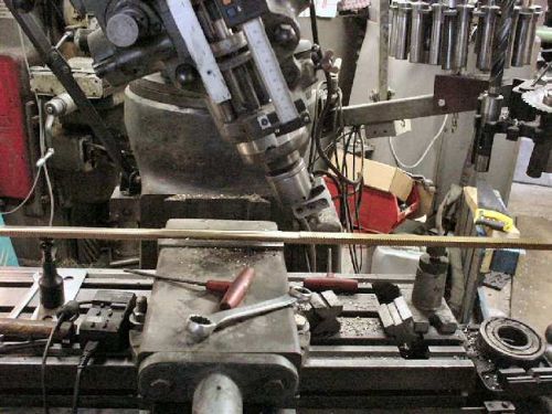
      Next week I have a long rack to make, about 1M long. At the moment I'm awaiting material as it non standard sized brass.

      I have done these before ages ago up to 1.5M long. Cutting the teeth is no problem I have a program on the CNC for this to do 1/2M at a time and move the blank.

      On the rear of the rack is a radius so it can bolt onto a circular linear tube which the rack drives up and down. The tube is 75mm in diameter.

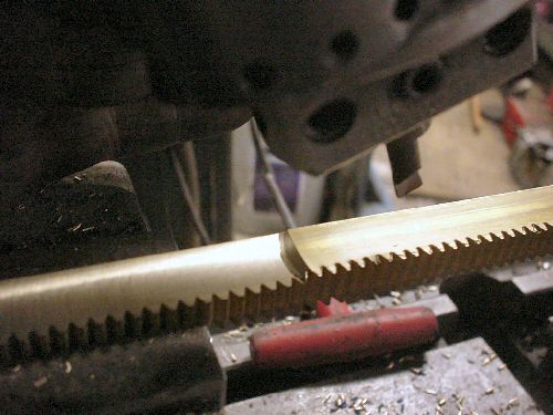
      The last ones I did I used the boring head in the mill with the head set over at an angle.

      And close up.

      The idea being that if the head is vertical you get a vertical hole and if the head is horizontal you get a horizontal hole so Gordon Bennett tells us that anywhere in between is an ellipse which over 16mm for the unwashed is an arc.

      So the question is what is the formulae to sort out this 37.5mm radius. I did find it on a web page but have since lost it.

      From memory the formula took into account the radius of the boring tool and the tilt angle.

      Advert
      #15818
      John Stevenson 1
      Participant
        @johnstevenson1
        #215862
        Clive Foster
        Participant
          @clivefoster55965

          Head angle 45°, boring tool set to cut radius of arc. Same as cutting a part spherical depression. Boring tool sweeps out the rim of a section through the centre of a sphere which must be a circle.

          Clive

          P.S. Asking on Practical Machinist as well is cheating.  Early enough over there that their brains are still awake not shutting down for bed-time.  Ought to have mremebered the lens makers equation tho' as I programmed a BBC B to figure that out for the optics shop "not telling you how many" years ago.  (Adcok Shpleys lens tooling version od the 1ES is one wierd looking beast.)

          Edited By Clive Foster on 10/12/2015 23:24:36

          #215863
          Emgee
          Participant
            @emgee

            John, Won't the radius of cut remain at 37.5 rad regardless of angle of the head ?

            Emgee

            Does this page help ?   1728.org/circsect.htm


            Edited By Emgee on 10/12/2015 23:40:29

            #215865
            Phil P
            Participant
              @philp

              John

              I just turned this up with a quick google search

              sin C = D/2Rc


              where C = angle of cutter with axis of work surface

              D = cutter dia

              Rc = desired radius of surface


              Exquisitely covered in A Treatise On Milling and Milling Machines, Third Edition (1951), Page 583

              Phil

              #215866
              John Stevenson 1
              Participant
                @johnstevenson1

                Clive the lens making formulae isn't any good I know the radius.

                What I want is the angle to tilt the head. It can't be 45 degrees as from the earlier example which used the same linear tube that head is nowhere near 45 degrees.

                I think Marv Klotz has a formula in his DOS based programs but it will take me too long to sort out how to run this.

                Reading A Treatise on Milling by Brown and sharp at the moment, might have been in there.

                #215867
                Roger Head
                Participant
                  @rogerhead16992

                  Clive, I've never made a cut like this, but surely the actual depth of the cut (i.e. from the edges of the rack to the trough in the centre) will be less than would be made if the boring tool was run horizontally. Because it can't be run horizontally for such a small radius cut, the angled-head is used, but the radius set on the boring head needs to be smaller than the desired radius of the cut. Without going through the geometry with a pencil and paper, I'd guess that for a 45deg angle of the head, the boring radius would be something like 1/root2 (i.e. 0.707) of the desired radius. So that would mean setting the boring tool to 26.51mm.

                  No guarantees!

                  Roger


                  Edited By Roger Head on 10/12/2015 23:44:39

                  #215868
                  John Stevenson 1
                  Participant
                    @johnstevenson1

                    Phil,

                    Bugger it, my copy only has 406 pages

                    #215870
                    Phil P
                    Participant
                      @philp

                      John

                      Here's another

                      http://www.angelfire.com/ks/mcguirk/generatingradius.html

                      My dad used this technique to make new wood blocks for the rear wheels of our Fowler road loco.

                      He used a big slitting saw tilted over to end up with a curve in the block to fit a 7 foot diameter wheel.

                      Phil

                      #215871
                      John Stevenson 1
                      Participant
                        @johnstevenson1

                        Phil,

                        That's the page I saw originally and it's the same as the formula you quoted only one uses diameter and one uses radius.


                        So a tool at 15mm rad and tube at 37.5 = 23.5 degrees which looks right for the picture


                        For the head to be at 45 degrees the cutter diameter need to be 53mm [ 53 / 75 = 0.707 approx ]

                        Edited By John Stevenson on 11/12/2015 00:06:10

                        #215882
                        Ajohnw
                        Participant
                          @ajohnw51620

                          The same technique is used to initially grind telescope mirrors and lenses. Convex or concave. I think it also slightly relates to how snooker balls are made.

                          John

                          #215896
                          Roger Head
                          Participant
                            @rogerhead16992

                            JS, as you probably know, the above formula are only approximate. I think that I have sorted the exact equation, as shown below. As you can see, the second-order effects only become significant when a reduction in the cutter radius approaches (channel width / 2) . In your case w/2 is 8mm and your cutter radius is 15mm, so the error in the approximation is small (~23.7deg vs exact 21.9xxxdeg), leading to a channel width that is approx 0.25mm narrower than your 16mm rack. Alternatively, if you advance the cutter until it occupies the full 16mm width, the channel depth will be marginally greater.

                            But in the greater scheme of things, it will hardly matter. The only real use of this is to emphasize that the simple approximation is just that, and to illustrate the effect of reducing the actual cutter radius too far.

                            Roger (E&OE smiley )

                            boring_equation.jpg

                            Edited By Roger Head on 11/12/2015 11:09:28

                            #215901
                            Roger Head
                            Participant
                              @rogerhead16992

                              Phil P

                              "Exquisitely covered in A Treatise On Milling and Milling Machines, Third Edition (1951), Page 583"

                              Any chance that you could scan/copy/xxx that bit, and post it?

                              Thanks, Roger

                              #215907
                              Phil P
                              Participant
                                @philp

                                Roger

                                I didn't find it in the book myself, I just googled it and that is what came up.

                                I probably do have the book but I will have to check when I am at home.

                                Phil

                                #215910
                                Michael Gilligan
                                Participant
                                  @michaelgilligan61133

                                  As the Season of GoodWill is upon us

                                  … Try here

                                  Individual pages are downloadable as PDF, without 'Partner login'

                                  MichaelG.

                                  #215911
                                  Muzzer
                                  Participant
                                    @muzzer

                                    Hmm. The path cut by the cutter will be elliptical, not circular, so this method will only give an approximation of a cylindrical surface.

                                    Probably not a massive issue if the rack only subtends a small angle at the centre of the tube ie its width is quite a bit smaller than the diameter of the tube.

                                    The only way to get a "good" fit would be to have the cutter axis completely parallel to the rack. Might be a problem with a Bridgeport, although IIRC, you have a horizontal (angle) head that would do the trick?

                                    If you want to avoid the rack rocking on the tube, you'd want to err on the side of having a smaller radius on the rack. That way it will sit on the outer edges of the curved face of the rack.

                                    Murray

                                    #215912
                                    John Stevenson 1
                                    Participant
                                      @johnstevenson1

                                      Thanks for the input lads but lets not over think this.

                                      It screws to the tube every 150mm or so and there are two roll pins, one either end to supply position.

                                      The rack is driven by a tiny stepper motor to raise and lower a transducer into a bath of water as part of Mr Rollsy Royce's crack testing gear. The linear tube is counter balanced so the loads on this tiny rack are minimal.

                                      This is the third rack I have done over a period of about 15 years and they must have over a dozen tanks.

                                      #215917
                                      jason udall
                                      Participant
                                        @jasonudall57142

                                        Ball nose cutter?

                                        #215919
                                        John Stevenson 1
                                        Participant
                                          @johnstevenson1

                                          75mm ball nosed cutter to do a one off job ?

                                          #215922
                                          Neil Wyatt
                                          Moderator
                                            @neilwyatt
                                            Posted by John Stevenson on 11/12/2015 16:52:40:

                                            75mm ball nosed cutter to do a one off job ?

                                            Brass rack? You could have made a silver steel one to do the job by now

                                            #215926
                                            John Stevenson 1
                                            Participant
                                              @johnstevenson1

                                              75mm silver steel ????????????????????????

                                              I'm nearly a bloody pensioner you know [ no bus pass ]

                                              #215927
                                              Les Jones 1
                                              Participant
                                                @lesjones1

                                                Page 583 extracted.

                                                milling_concave.jpg

                                                Les

                                                #215936
                                                Robert Dodds
                                                Participant
                                                  @robertdodds43397

                                                  John,

                                                  i'm going on theory, not practice, so I will stand correction , but I think you can get a true arc at 37.5 rad if you set your boring tool to 37.5 (70 dia.) and do a compound incline of the cutter head. The inclinations should be equal but to save any complications its probably easiest to do both at 45 degrees, sins and cosine being equal. As Clive Foster suggested early on, your cutter describes a spherical path which forms a gutter (what your after) as it progresses along the X axis.

                                                  Bob D

                                                  #215938
                                                  Chris Evans 6
                                                  Participant
                                                    @chrisevans6

                                                    If you have CNC why not program a cherrying operation in Y Z and peck along the X axis ? I have used a boring head as you show and had good results also used a Cherry head on the Bridgeport.

                                                    #215943
                                                    Chris Evans 6
                                                    Participant
                                                      @chrisevans6

                                                      Les, that set up is how I used to produce the dies for oil and fuel filter housings. The dies I made had a round form but the principal was the same just rotated on the rotary table. Providing the wall section was OK no one measured the end result ! CNC now does it better and with great accuracy. Chris.

                                                    Viewing 25 posts - 1 through 25 (of 32 total)
                                                    • Please log in to reply to this topic. Registering is free and easy using the links on the menu at the top of this page.

                                                    Advert

                                                    Latest Replies

                                                    Home Forums Workshop Techniques Topics

                                                    Viewing 25 topics - 1 through 25 (of 25 total)
                                                    Viewing 25 topics - 1 through 25 (of 25 total)

                                                    View full reply list.

                                                    Advert

                                                    Newsletter Sign-up