First time using a milling machine

Advert

First time using a milling machine

Home Forums Hints And Tips for model engineers First time using a milling machine

Viewing 25 posts - 26 through 50 (of 51 total)
  • Author
    Posts
  • #154390
    Andy Bladen 1
    Participant
      @andybladen1

      Some interesting advice thank you all

      i will try a 2 flute hss endmill and see if that works better

      as mentioned above I did have problems with the chips welding to the mill maybe I was going too fast and clearing them away enough especially using a 4 flute mill

      Advert
      #154391
      Anonymous

        Since I am machining some 6082 plates this morning I thought I do some experiments along the way. There are two plates, 690mm by 250mm and 8mm thick, which need bringing to size and squaring.

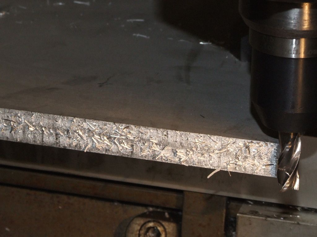
        I am using an uncoated 3 flute carbide 10mm slot drill running at 2000rpm and a feedrate of around 650mm/min. In all cases I am cutting both plates together, so depth of cut is 16mm. First, conventional milling without coolant and a width of cut 1mm:

        conventional_dry.jpg

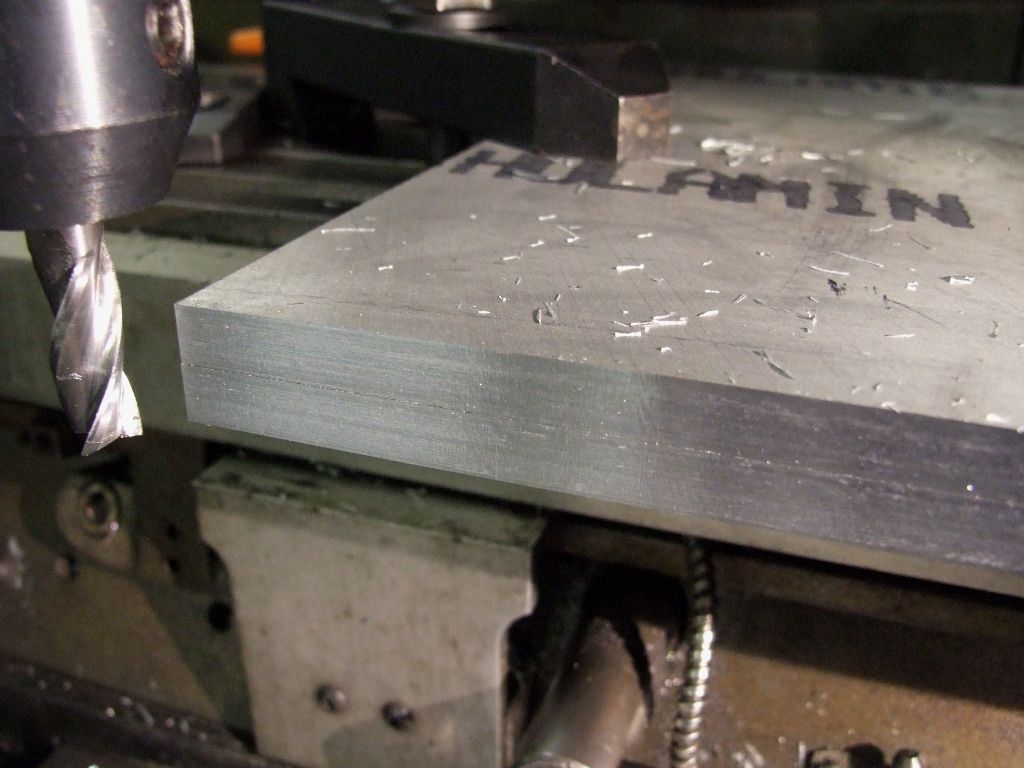
        Finish is rougher than a badgers ****. Looking closer the finish actually isn't too bad, but the chips are 'welding' to the work, but, oddly, not to the cutter. Here is the result of climb milling, also dry, width of cut 0.5mm:

        climb_dry.jpg

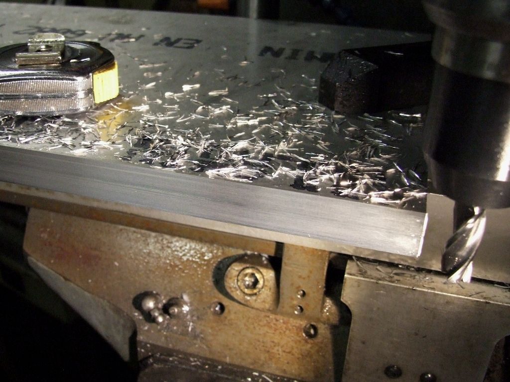
        Not a bad finish, it feels nice and smooth; I don't have time to muck about measuring the Ra. And finally conventional milling again, same parameters as before, with a squirt of WD40 every 2 or 3 inches:

        conventional_wd40.jpg

        I generally climb mill for the last cut on aluminium, carbon steel and stainless steel. For brass and cast iron it doesn't matter, and for plastics climb milling seems to give a badgers **** style finish.

        Now, back to the grindstone, well alright back to the mill.

        Regards,

        Andrew

        #154394
        MadMike
        Participant
          @madmike

          Thanks John (Bog Standard) for that explanation and graphics. This is the problem that I was alluding to in my earlier posting.

          Thanks also to John Stevenson for his additional contribution regarding cutters, coolant/lube etc.

          Thanks to Andrew for his pictures, clear description and illustration of the need to get feed, speed and depth of cut right.

          Finally, Andy the information here is invaluable and come from people with vast experience. I would initially practice the machining to get accurate sizes and good consistent surface finish before trying to make complex components. You will then be better equipped to make quality components in the future. After all "practice makes perfect" as my old granny used to tell me. She had 10 children and said that the practice was very important.

          #154395
          Russ B
          Participant
            @russb
            Posted by John Stevenson on 04/06/2014 09:15:24:

            On hobby machines you will have no maximum speed limit of Aluminium and the fast the cut the better. Run fast, light cuts and many of them.

            Keeping in mind my statement "if it doesn't work for me, I'm probably doing it wrong" – we've essentially advised the opposite approach so I thought I might go in to my situation a bit more to differentiate as I've tried your approach and it didn't work at all – I was cutting a blind slot so those small chips had no where to go – I just made finer chips, and the cutting fluid turned it to a paste which polished and took the sharp edge off the cutter and just created more heat and the problem snowballed – I was eventually just melting my way though the material rather than cutting – it was obvious that flood coolant would have solved my issues but it wasn't an option.

            I think your method would work well if drilling the perimeter and then facing to the final size with the work raised to allow chips to fall through which is obviously what the OP is doing.


            For my blind slots then should you encounter any……..
            I went to larger cuts, lower speed (max speed on the low range circa 1000rpm, vs 2000 on the high range) – just a smear of lube applied with a brush to the surface of the material so it picked up a little as I was cutting and a vacuum constantly clearing the chips this gave me good results and I was removing material at a decent speed – no one has shown me anything so I am just making this up based on what worked for me

            Edit* Worth mentioning, on my Chester 20V, 2500rpm on the same job, same method cuts at 3 times the speed with an even finer finish, so maybe my issues were to do with deflection on the X1 although it had a rigid column and I'd hand scraped the new column square to the table and it was pretty much bang on with tight brass gib strips and 0.05mm backlash on home made split nylon nuts – I could have gone to 0 but it started to drag a bit.

            Another edit in light of Andrews post – thats a Bridgport if I'm not mistaken……. its a 950kg or more of mechanical marvel that's been recognisable for almost 100 years depending on the model – should we really be comparing it to a <35kg Chinese desktop machine to evaluate surface finish

             cheeky

            Edited By Russ B on 04/06/2014 11:52:36

            #154399
            magpie
            Participant
              @magpie

              Dave Daniels. I have sent you a PM.

              Cheers Derek.

              #154402
              Russ B
              Participant
                @russb

                ok "almost 100 years" is a bit of exaggeration, 75 is more accurate – but you get the point

                Andy (the OP, and anyone else reading this thread in years to come……) you'll notice a vast range of experience and many who get miffed by light headed folk like myself offering (largely bad) advice, please don't take it as advise, its just a shared experience and some inexperienced folk may not highlight that on forums (any forum, any subject) – picking out the good advice from the bad is a skill in itself in my opinion.

                I consider my situation very similar to your own, and milling is a topic to large and to complex to understand without many years guided experience or proper education, face to face – but after many years guided experience certain things might be taken for granted like machine ability – and this is what I'm trying to highlight – a very different approach might be needed to overcome machine limitations on todays far eastern equipment and strange variables will creep in that were once taken for granted.

                #154405
                John Stevenson 1
                Participant
                  @johnstevenson1

                  Andrews post raised a good example though.

                  OK he's got a Bridgeport but I rate these only one step up from an X1 as regards rigidity unless you have the deluxe model with high tensile licorice column.

                  His first pic was conventional milling with a 1mm width of cut, last pic was same operation i.e conventional but with width reduce to 0.5mm and a tad of knacker lacquer which as everyone knows adds lustre to your cluster.

                  Speed stayed the same. The enemy of machining is usually speed because at some point the surface feet per minute exceeds the cutter material limits, using carbide can and does increase these levels as does increasing the size of cutter which also has the effect of increasing the surface speed.

                  However on HSS in alloy it's very hard to exceed these in a soft material. Guessing this cutter belonging to the OP is 5mm then max speed in alloy for HSS is close to 4,000 rpm, a speed most hobby machines can't do.

                  This is why I based my advise on run fast but small cuts, a strategy that Andrews results show advantages.

                  Recutting of chips is a problem and whilst it can be helped by speed and feed the real answer is to get them out of the way. It's like walking thru a mine field, it can be done but slowly, now if there were no mines you could run thru.

                  Chips are a problem, deal with them and move on to the next problem, don't try to compensate for a known problem.

                  On the scale we are talking here, X1, X2, WM14 etc, sized machines and speeds involved a decent vacuum cleaner will do the job as well as an air line.

                  #154415
                  Andy Bladen 1
                  Participant
                    @andybladen1

                    Once again thank to everyone who has taken there time to contributed to this thread it's certainly invaluable advice I will take on board to try and improve my work

                    i am a complete newbie and still learning we never did a lot of engineering and metal work at school sadly

                    #154418
                    Ian S C
                    Participant
                      @iansc

                      On little jobs like this, the chips can be cleared (depending on your lung power). A piece of plastic tube, about 18" long, and 5 mm 6 mm bore, and blow, only little puffs are needed. I'v just acquired a small compressor, a medical one by De Vilbiss. Ian S C

                      Edited By Ian S C on 04/06/2014 14:08:06

                      #154421
                      Andy Bladen 1
                      Participant
                        @andybladen1

                        Ian

                        Great advice I was blowing the chips away it makes a lot of mess but worth it to help keep the cutter free

                        surprising how much mess can be made from such a small part !

                        #154453
                        Muzzer
                        Participant
                          @muzzer

                          I find that climb milling allows a heavier cut before the onset of chattering is provoked, which is another reason for going that way. I have a life to live, which doesn't involve taking longer than necessary on operations like this, even though it's a hobby.

                          There is a balance between tightening up the slides enough to prevent the work being drawn uncontrolledly by the cutter (helping itself to the backlash) and being so tight that it makes turning the handle difficult. With practice you can back off the slide locks so that you still need some margin of effort to turn the wheel but you can feel that the cutter is assisting with the feed. If (like me) you have noticeable backlash, you can break the cutter very easily by climb milling without remembering to tighten up the slides. I take great care to avoid this!

                          The pulling force exerted by the cutter is affected by the radial depth of cut, so there must be a "neutral point" with climb milling where the required feed force is zero in the direction of feed. So, taking light cuts is more hazardous in some cases than taking the plunge, so to speak.

                          Murray

                          #154462
                          Andy Bladen 1
                          Participant
                            @andybladen1

                            Daft question. But how would you clamp the work piece to the table ?

                            my first attempt was to bolt the alu down onto a piece of wood so not to mill into the table problems I found was there wasn't anywhere for the chips to fall away apart from blowing them which did work to a point

                            I thought about using a vice but once I cut most of the frame I thought the vice might crush the remaining metal

                            #154487
                            Anonymous

                              Yes, one of my mills is a Bridgeport. I normally give it a stern talking to before use, straight back, stiff upper lip and all that sort of thing, tends to stiffen it up no end. wink 2

                              I'm not suggesting that the OP tries to replicate the cutter speeds, feeds and cut sizes, but was merely illustrating the types of finish that might be obtained. I'm no expert, but I've never come across a metal that is sentient, and says to itself that it is on a hobby machine, so it is going to behave differently while being cut. smile

                              In my experience deflection is normally an issue of dimensional accuracy rather than surface finish. Manual and CNC, I normally leave a small amount for a final cut to minimise tool/machine deflection.

                              For pocketing in aluminium and steel I use flood coolant to remove the swarf. For plastics I use a vacuum cleaner; I should be a beta tester for Dyson! For short chipping materials like brass and cast iron I often just blow it away, using a pipe or even a straw.

                              Andy: I'll mull over some ideas on how to machine your part and post tomorrow.

                              Regards,

                              Andrew

                              #154488
                              Muzzer
                              Participant
                                @muzzer

                                A component like yours would naturally clamp to the table, using pieces of aluminium strip as spacers to save the table and the cutter – wood might be a bit too spongy. It doesn't look as if a vise would do it much good. Once you have machined the cavities, you could move the clamps without disturbing the work so they are bolted through the cavities, allowing you a clear run at machining the outside profile.

                                Thinking carefully about workholding before you start machining can save hours of setting up between operations. If the finished article has fixing features you can often use them to hold the work down, and thus simplify matters. Alternatively it may be worth leaving a couple of hold down lugs which you can remove at the end, manually if necessary.

                                There are times when you can't avoid removing the workpiece and you have to be very careful getting it set up again. This is where gadgets like DROs can save lot of time and improve accuracy.

                                Murray

                                #154498
                                Andy Bladen 1
                                Participant
                                  @andybladen1

                                  Murray

                                  great idea I never thought about using spacers this should allow the chippings to fall through and hopefully prevent clogging

                                  I tried using wd40 but it just made a paste and the alu welded itself to the mill

                                  this uses should hopefully work th least amount of times I have to un clamp the material the better

                                  as you say most of the time is taken up setting the work piece

                                  #154501
                                  Bob Brown 1
                                  Participant
                                    @bobbrown1

                                    When machining aluminium I use a mix of 95% paraffin and 5% oil and spray it on the work piece using a small hand garden sprayer. I add the so the table ends up with a layer of oil after the paraffin has evaporated.

                                    Some times the swarf issues can not be avoided, when you are machining a slot, in this case I use the air line to keep the tool clear or if taking a wide cut a brush.

                                    If I need to machine a slot accurately I rough it out first and then finish it cutting both sides and bottom.

                                    As far as work holding I tend to set stops for the work piece so that I can remove it if need be or allows more than one item to be machined at the same settings.

                                    Bob

                                    #154592
                                    Anonymous

                                      As promised, here's one way of machining the part, building on what Muzzer has said. And I would agree that wood is not really a suitable base. I sometimes use offcuts of MDF when drilling on the mill, but that's about it.

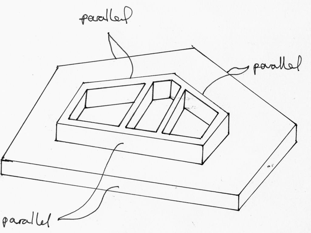
                                      I assume that you need to make more than one of the part? First make a sacrificial aluminium baseplate to hold the part. Then add two tapers to the top edge of the baseplate that match the angles on the top of the part. That way the part can easily be set parallel to the table travel to machine said tapers. I use a piece of gauge plate tapped into a T-slot for quick alignment with the table.

                                      Then accurately drill the corners of the internal pockets, using a drill sized to give the desired internal radius. Chain drill between those holes to remove the majority of the material. An endmill can then be used to clean up the internal edges. I suspect the internal pockets don't need to be that accurate so the milling can be done by eye with reference to the corner holes. One can drill a hole or two right through the baseplate so there is somewhere for the swarf to go.

                                      Then reclamp the part and chain drill, or just mill, the outer profile, using the edges on the baseplate to set the angles.

                                      I expect you can work out the last few operations, as you have already successfully made a part.

                                      Regards,

                                      Andrew

                                      #154595
                                      Andy Bladen 1
                                      Participant
                                        @andybladen1

                                        Andrew

                                        thanks for that info I will try that method this weekend as soon as I buy a new endmill!

                                        Still a little unsure about the tapers and how that works

                                        if you could post a diagram of some kind that would be great

                                        the crucial part where the accuracy needs to be precise is the slope

                                        this is where I have to make a carriage to slide up and down

                                        i was hoping to use a t slot cutter if I can find one small enough (around 6.5mm)

                                        #154596
                                        Andy Bladen 1
                                        Participant
                                          @andybladen1

                                          image.jpgimage.jpgThis is the next part I need to create or something similar

                                          #154606
                                          Andy Bladen 1
                                          Participant
                                            @andybladen1

                                            John

                                            Around 20mm square would be ideal they have to be quite small and a total of 8 I'd need there are 2 for each flap per wing

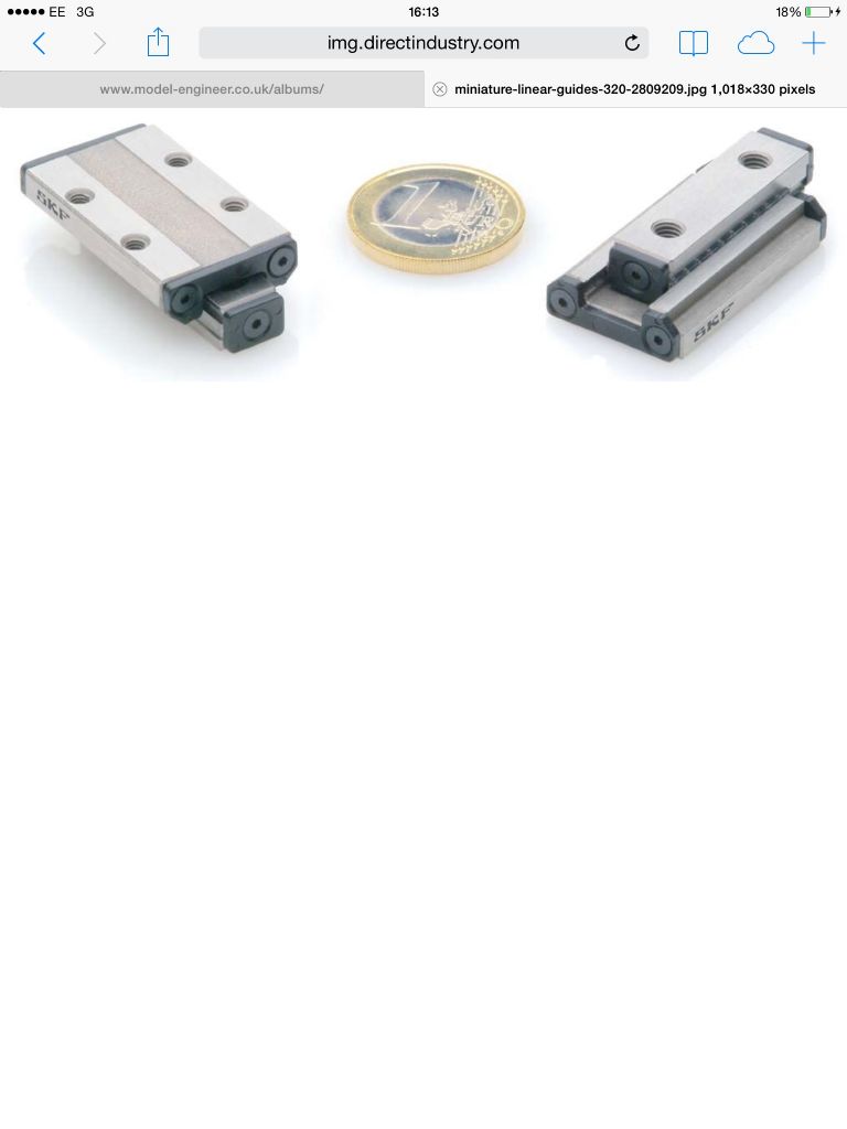
                                            I've looked on Google but they seem to be really expensive and a bit to big

                                            failing that I will have to attempt making the top one 2mm roller bearings of some kind would work

                                            cheers Andy

                                            #154609
                                            Neil Wyatt
                                            Moderator
                                              @neilwyatt

                                              How 'scale ' do you need?

                                              You can get nylon blocks that slide in a shaped steel channel as part of devices for stopping doors opening to far. You could copy those.

                                              Neil

                                              #154612
                                              Andy Bladen 1
                                              Participant
                                                @andybladen1

                                                Neil

                                                the mechanism will be hidden away so that might work as long as it travels up and down the slope without binding

                                                Andy

                                                #154615
                                                Ian P
                                                Participant
                                                  @ianp

                                                  Andy

                                                  Definitely worth looking at the IGUS catalogue. They do quite a range of linear tracks and runners made from engineering plastics and aluminium. They are surprisingly accurate and I think they go down to quite small sizes.

                                                  Ian P

                                                  #154617
                                                  Muzzer
                                                  Participant
                                                    @muzzer

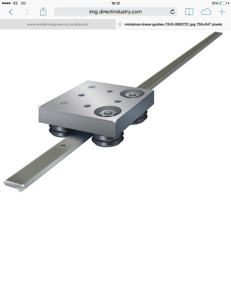
                                                    For stuff like linear guides, head over to AliExpress and have a look around there. You should be able to get something delivered in a week or so for not a lot of dosh. AliExpress is not a complete Wild West experience, as there are some safeguards in place to protect buyers like us.

                                                    If money is not the issue, how about Misumi. Talk about playgrounds for grownups!

                                                    Murray

                                                    #154633
                                                    Anonymous

                                                      Andy: Here's an idealised sketch of the part and baseplate that I hope illustrates what I meant by the angles.

                                                      baseplate.jpg

                                                      I suspect that the use of linear guides for the flap mechanism is rather an over-complication. All the aircraft that I've flown with Fowler style wing area increasing flaps had pretty crude rollers and guides, with a fair amount of play. I recall about 1/4" to 1/2" play at the trailing edge of the extended flap. The problem with a nice accurate mechanism with close fit tolerances is that the whole lot binds solid the first time you try to operate it with the wing bending under flight loads.

                                                      Regards,

                                                      Andrew

                                                    Viewing 25 posts - 26 through 50 (of 51 total)
                                                    • Please log in to reply to this topic. Registering is free and easy using the links on the menu at the top of this page.

                                                    Advert

                                                    Latest Replies

                                                    Viewing 25 topics - 1 through 25 (of 25 total)
                                                    Viewing 25 topics - 1 through 25 (of 25 total)

                                                    View full reply list.

                                                    Advert

                                                    Newsletter Sign-up